
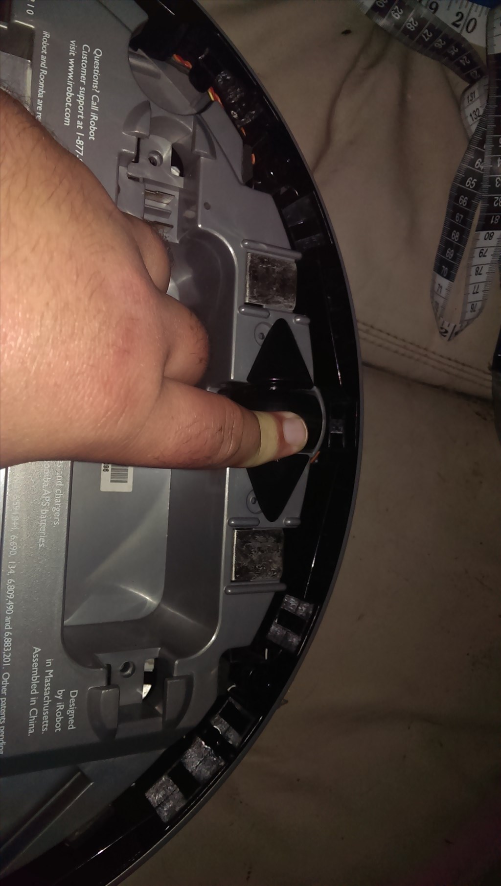
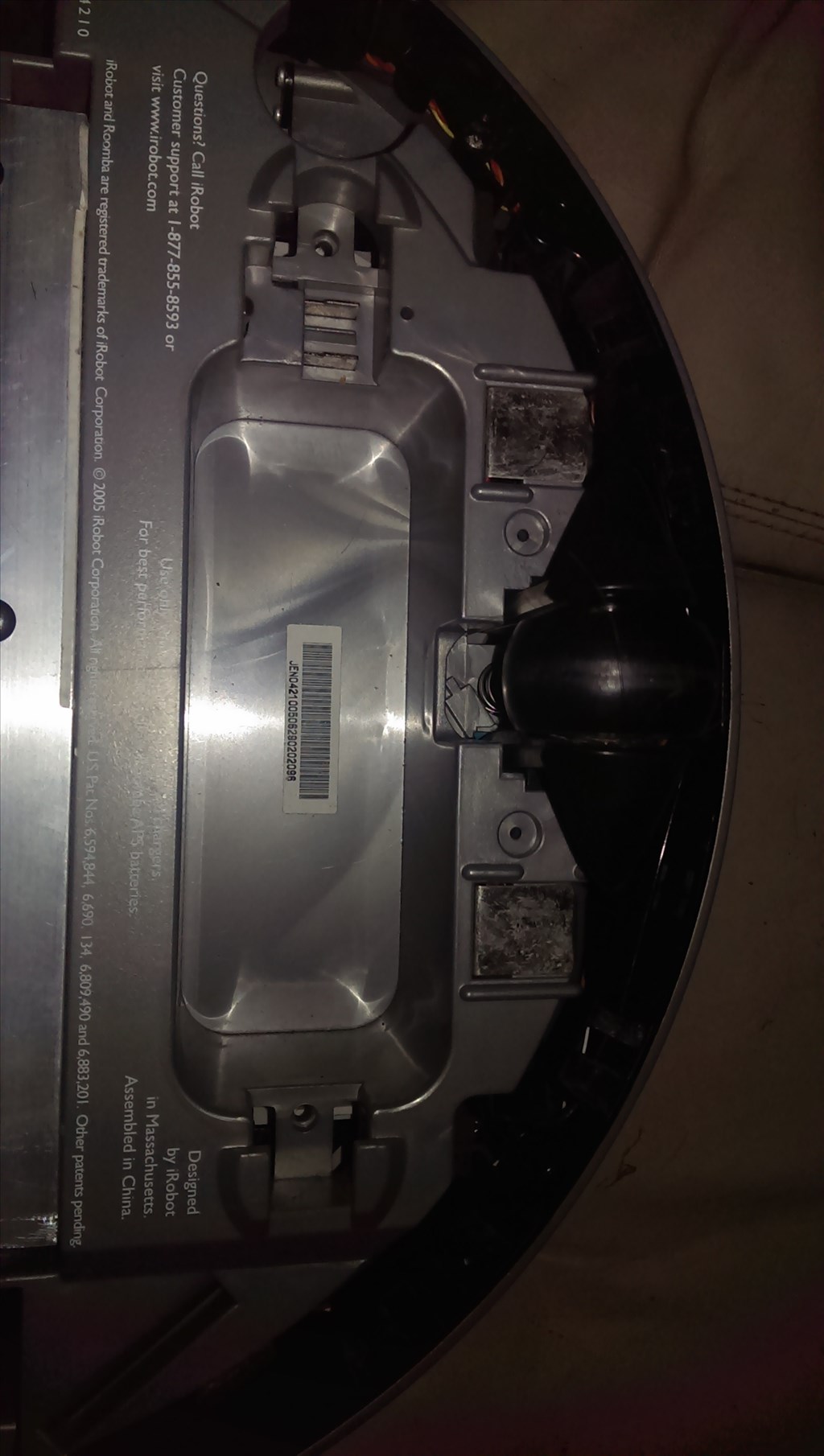


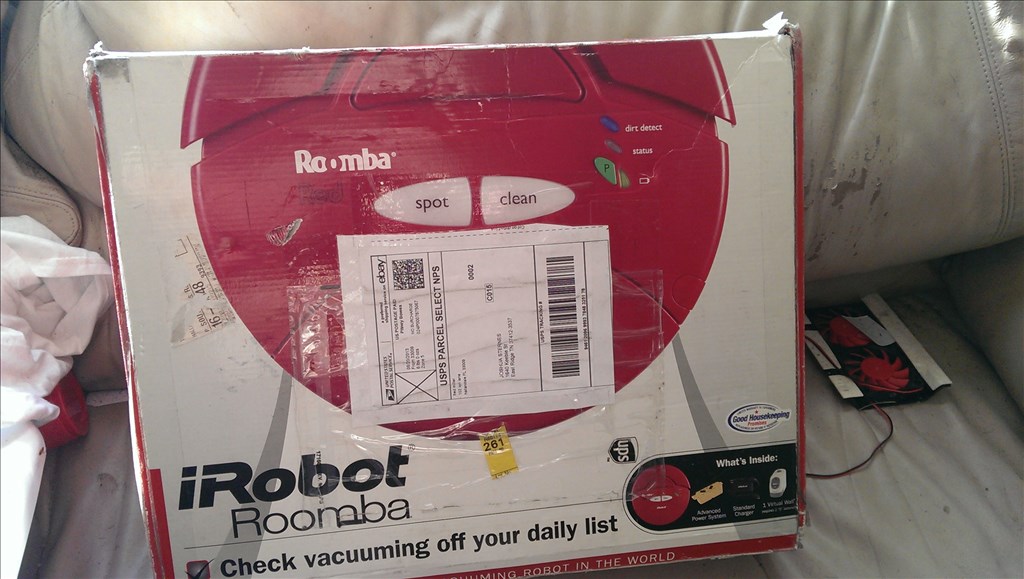
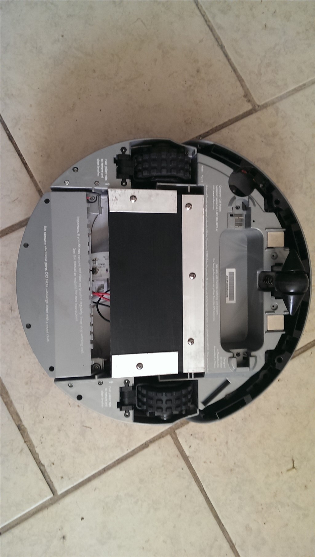
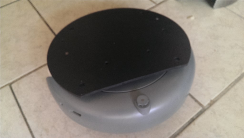
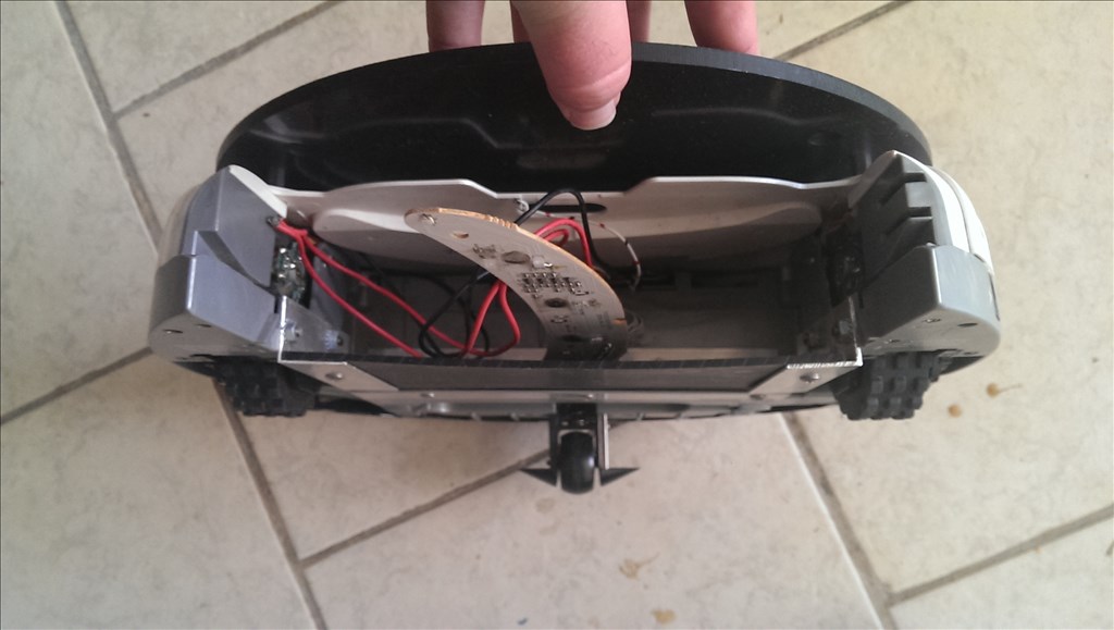
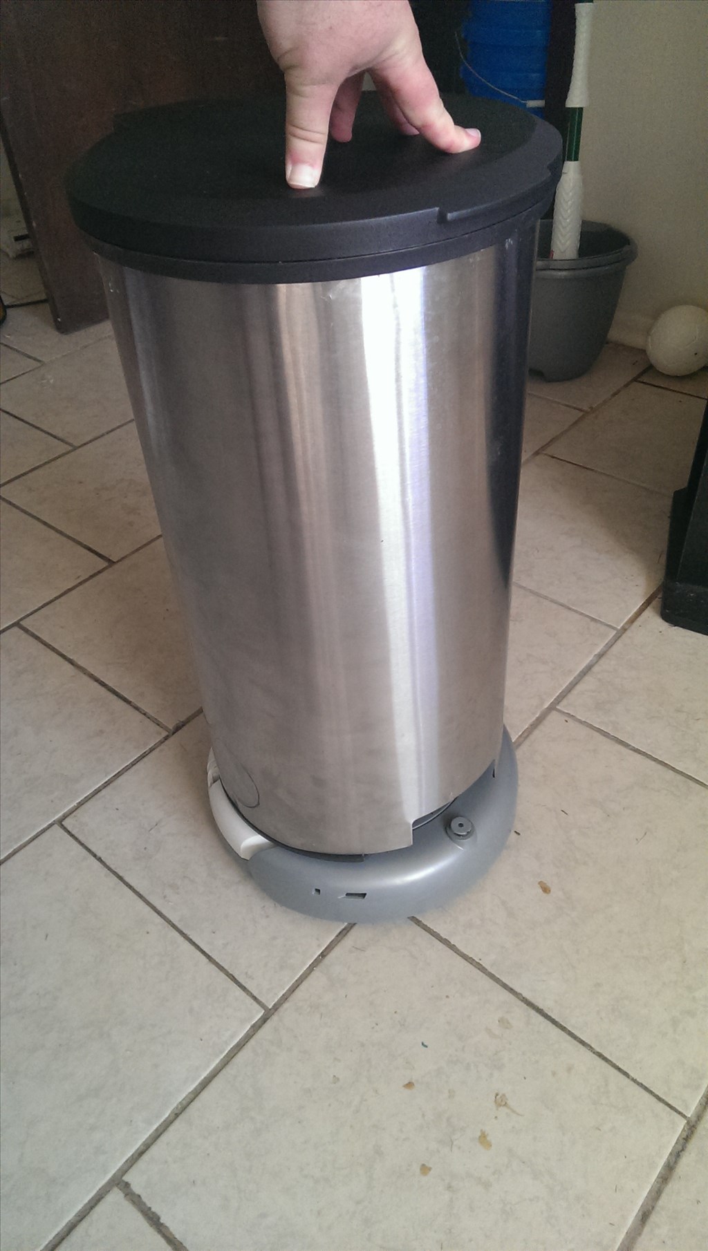


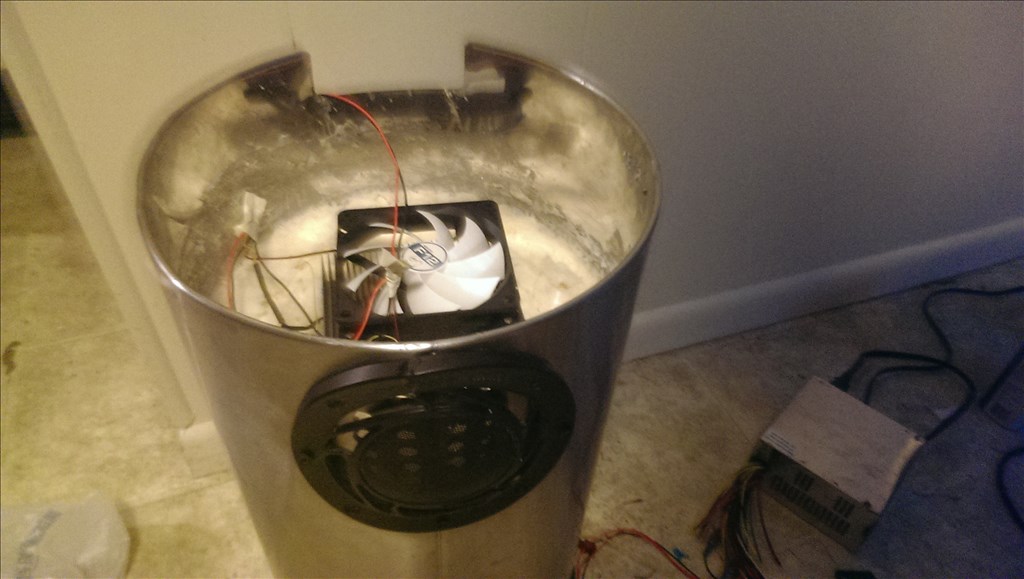


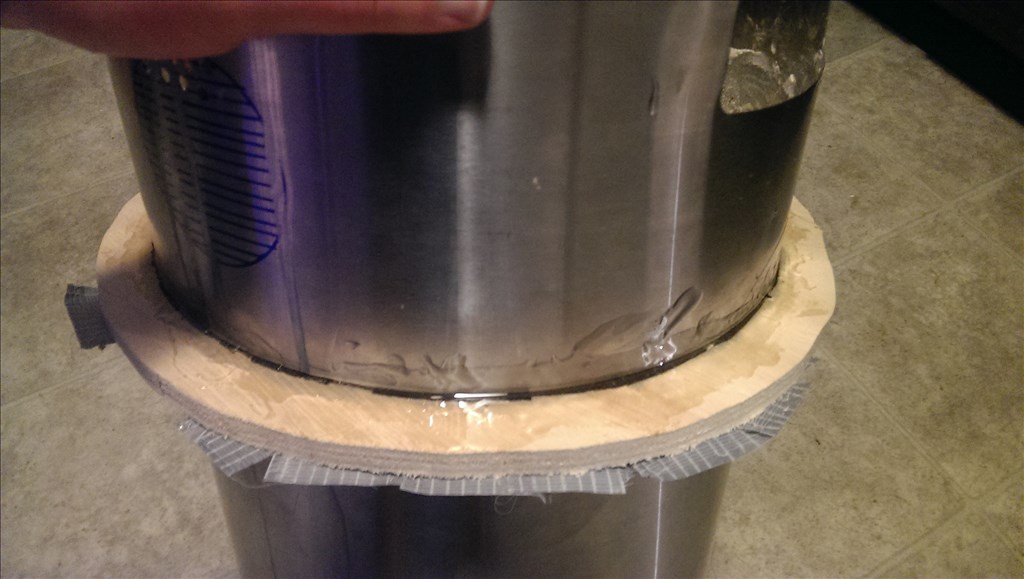
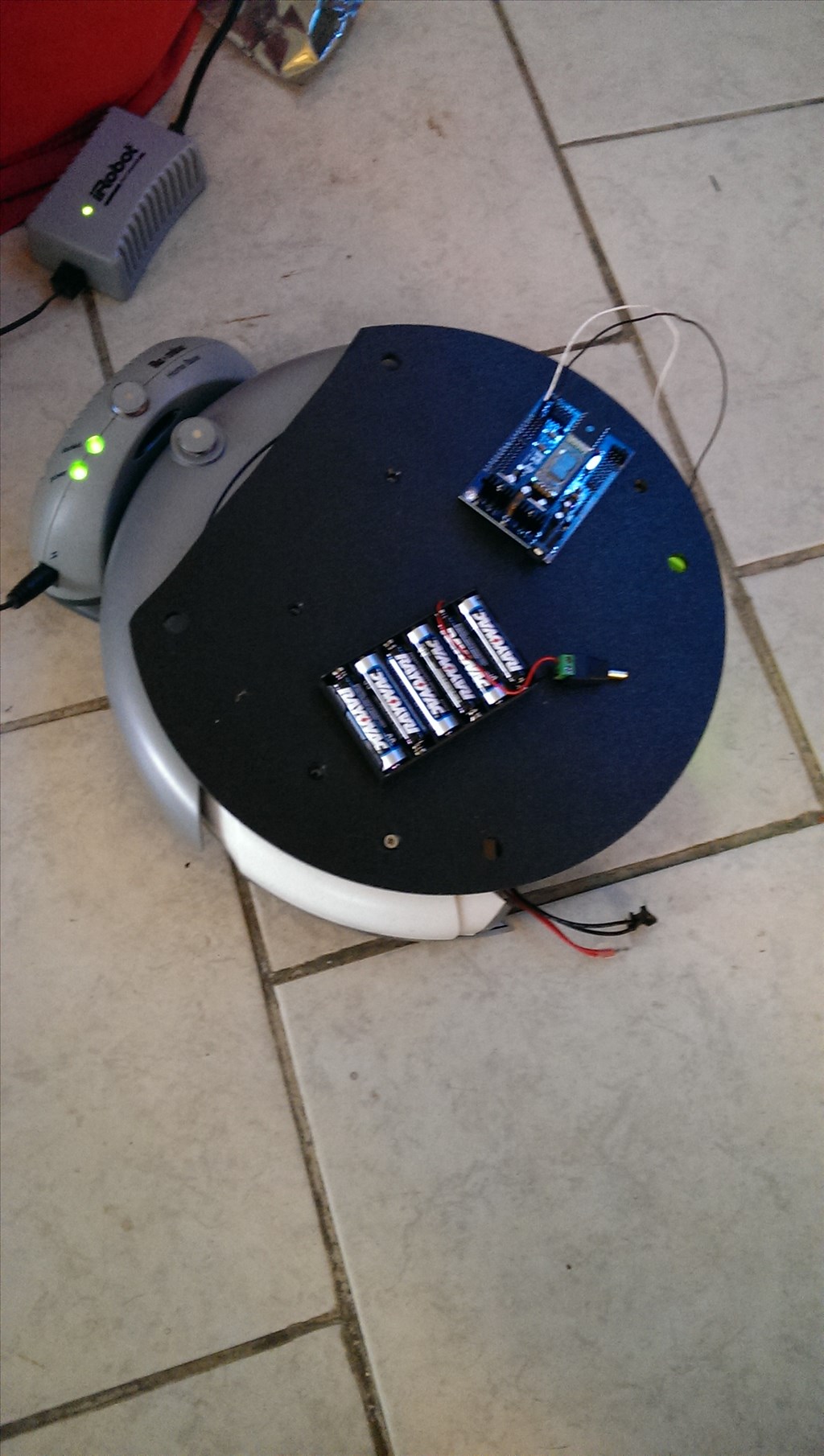
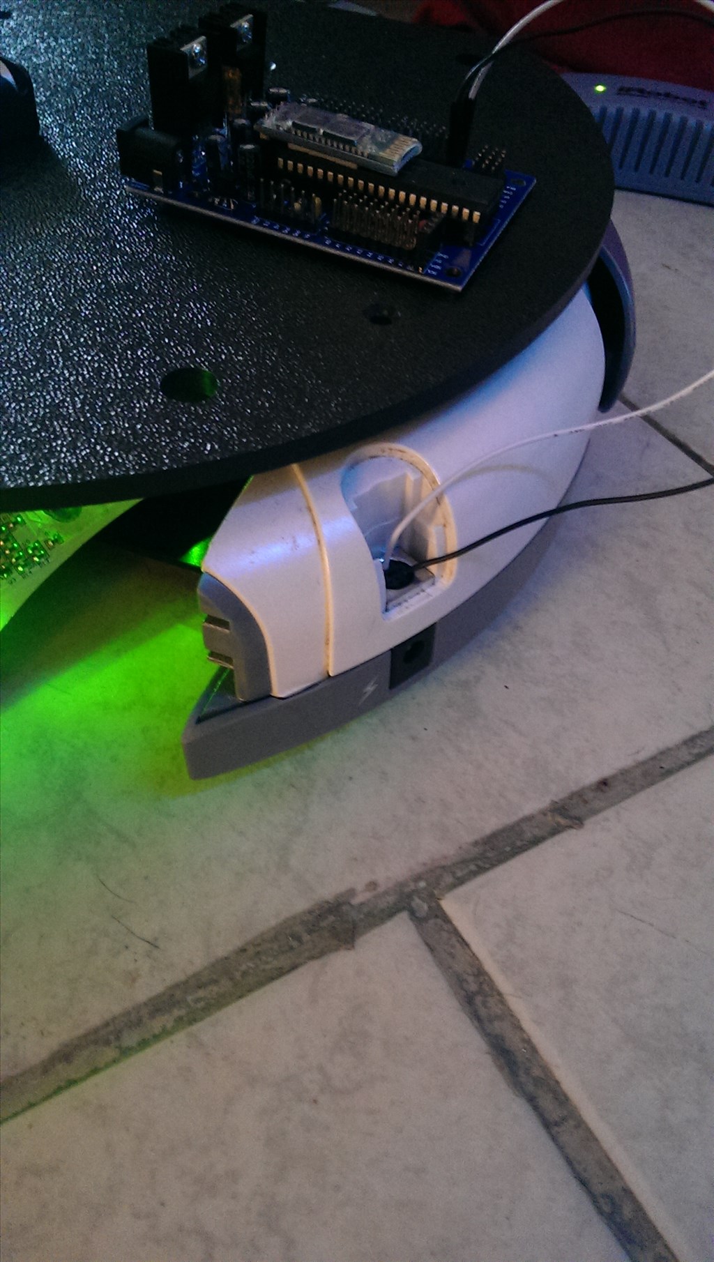
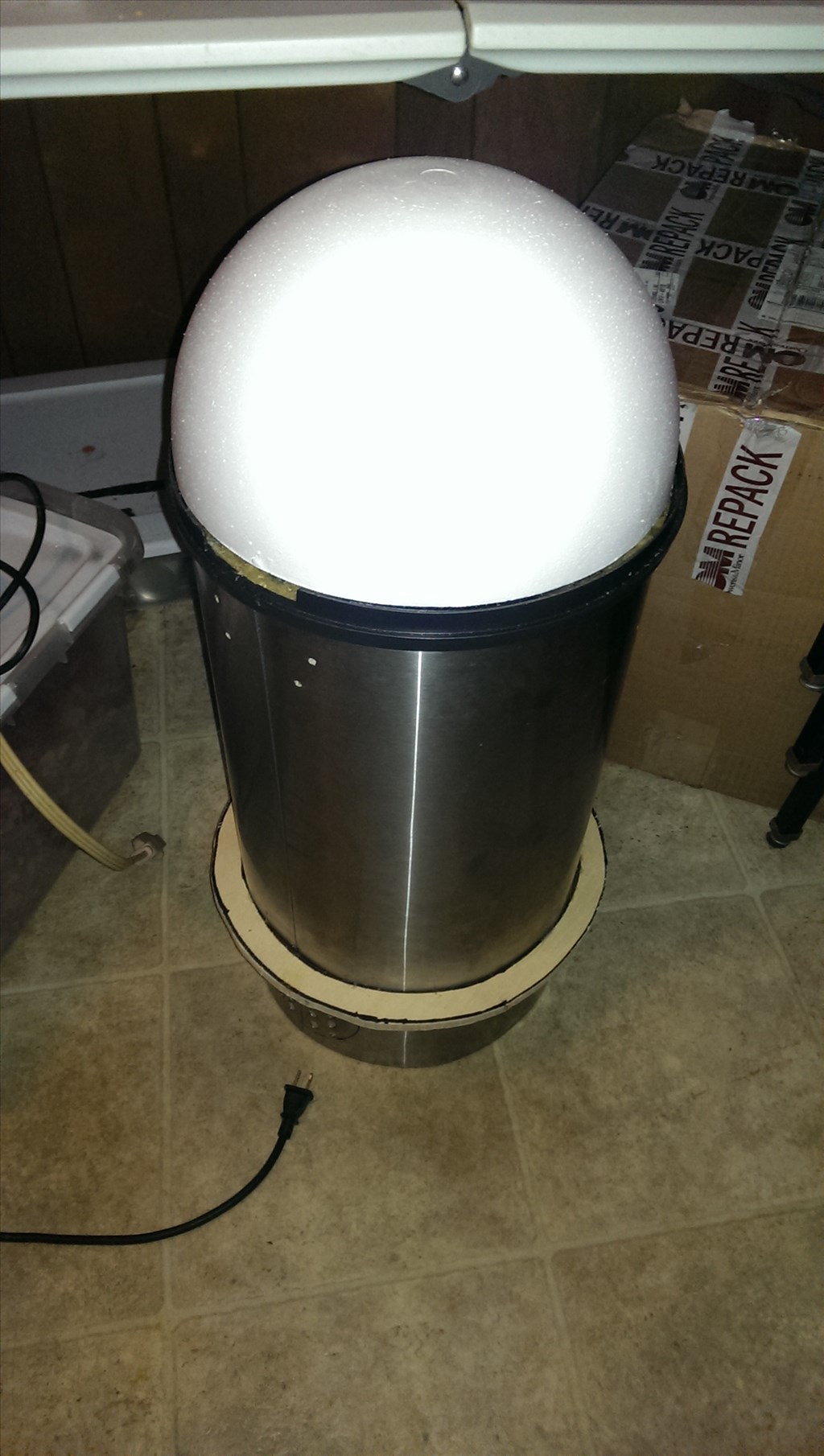

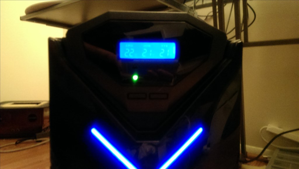
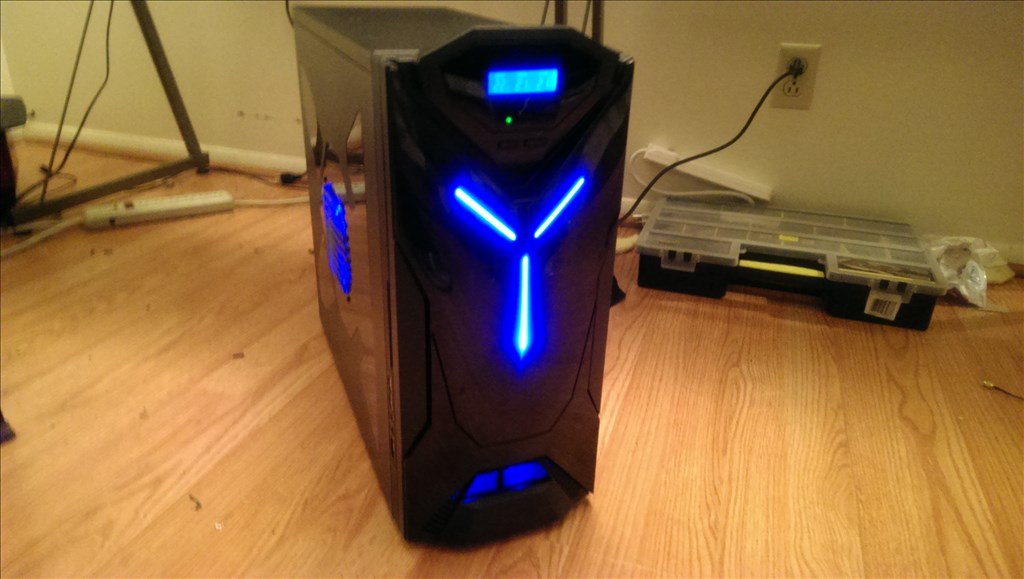


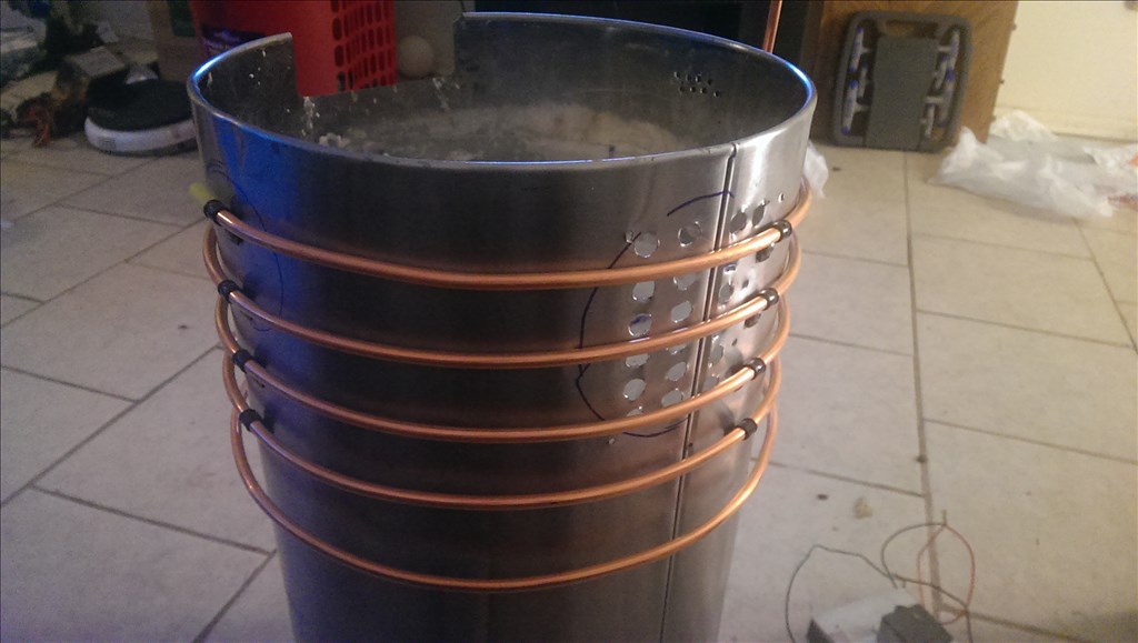
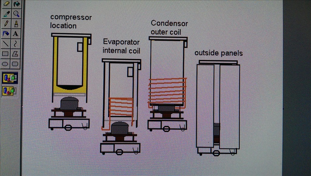


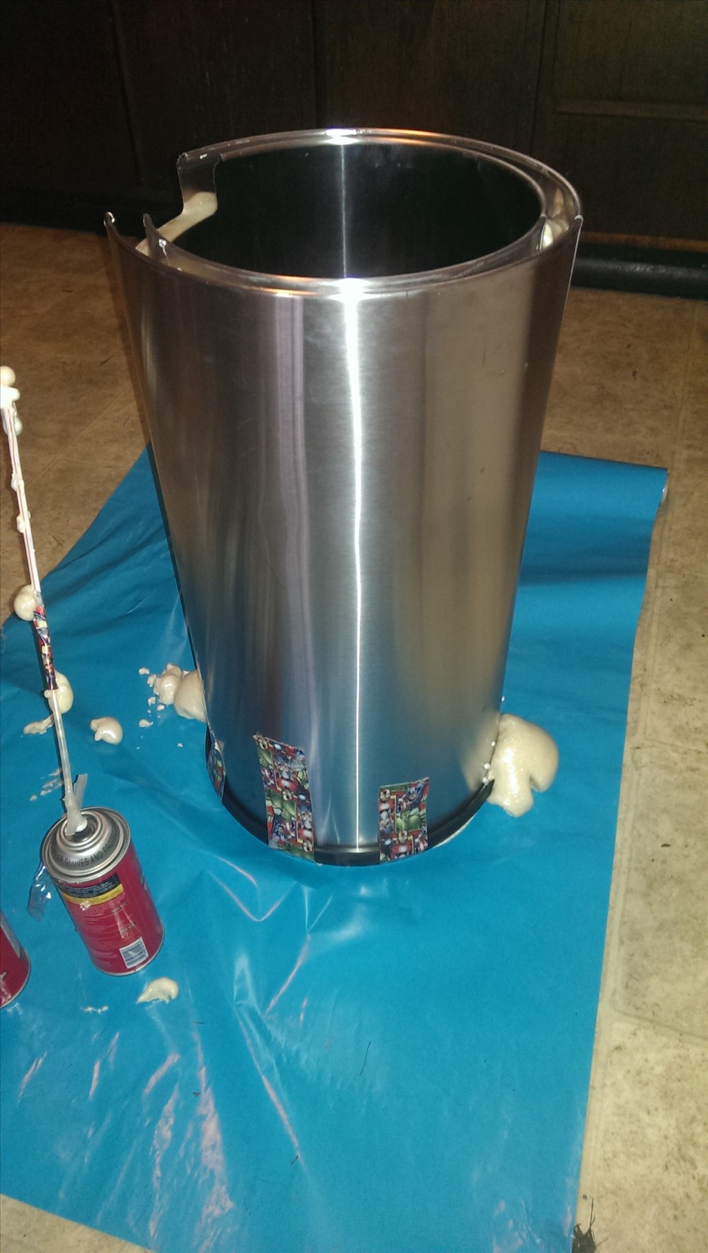


This is a challenge issued by friends and family. The goal here is to make a robot that can bring beverages from another area to wherever the people are , allow the person to get their drink , then leave. It does not need to be fully autonomous , even remote control is acceptable. It does not need to grab them from the fridge, preloaded beverages are acceptable. This is Ez Robot though, I believe we could do better than that! Well anyways to start the project off I am using a roomba base. I picked up a stainless steel trash can last night as a outside casing. I will show you the rest as we go
By jstarne1
— Last update
Discover more robots
Ezang's Simple Bot Car Robot
Simple Bot car using 2 continuous servos, IoTiny controller with speaker, ServoCity parts and Synthiam ARC for servo...

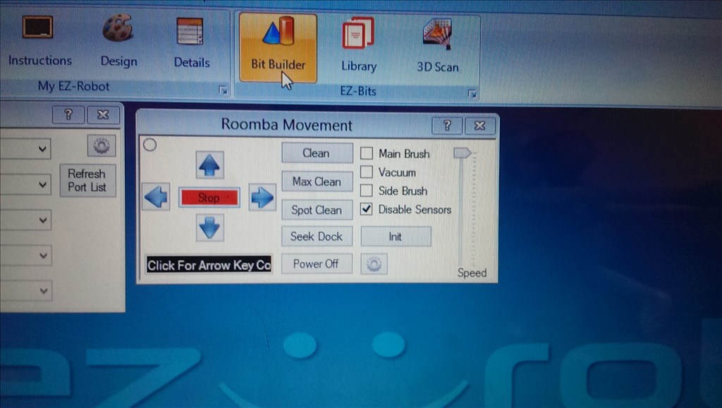
Lumpy's Lumpy's Roomba Rover
Upgrade Arduino 4WD chassis with Roomba wheels for straighter motion; H-bridges mounted, connectors pending, EZ-B...
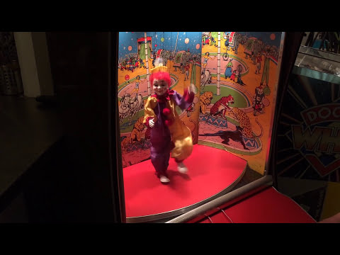
Dave's Bimbo The Clown
EZ Robot revives classic amusement games with DJ's Bimbo The Clown-fun retro entertainment and creative community...

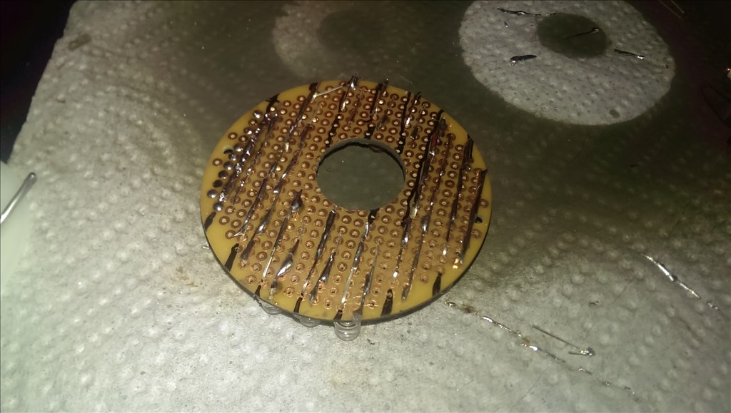
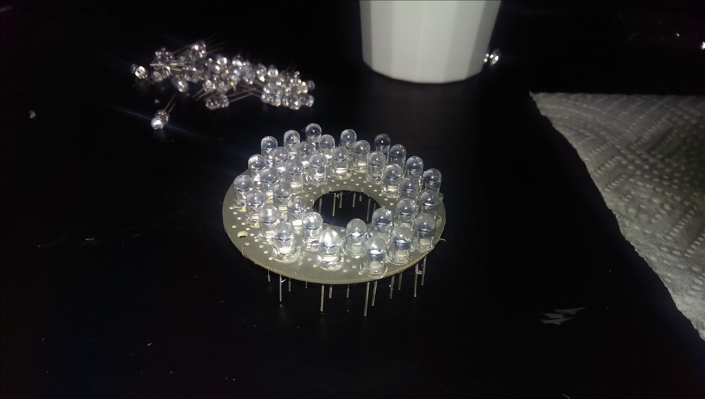
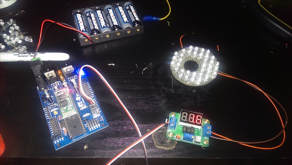
you can draw inspiration from this model
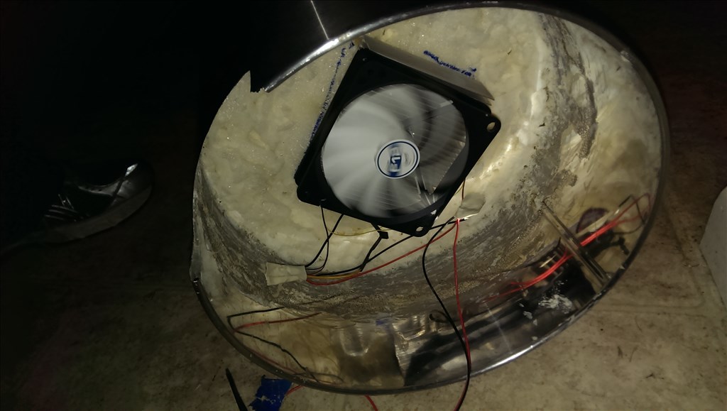
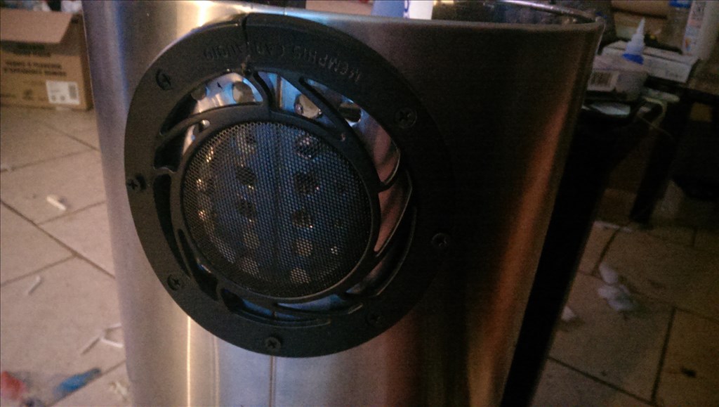
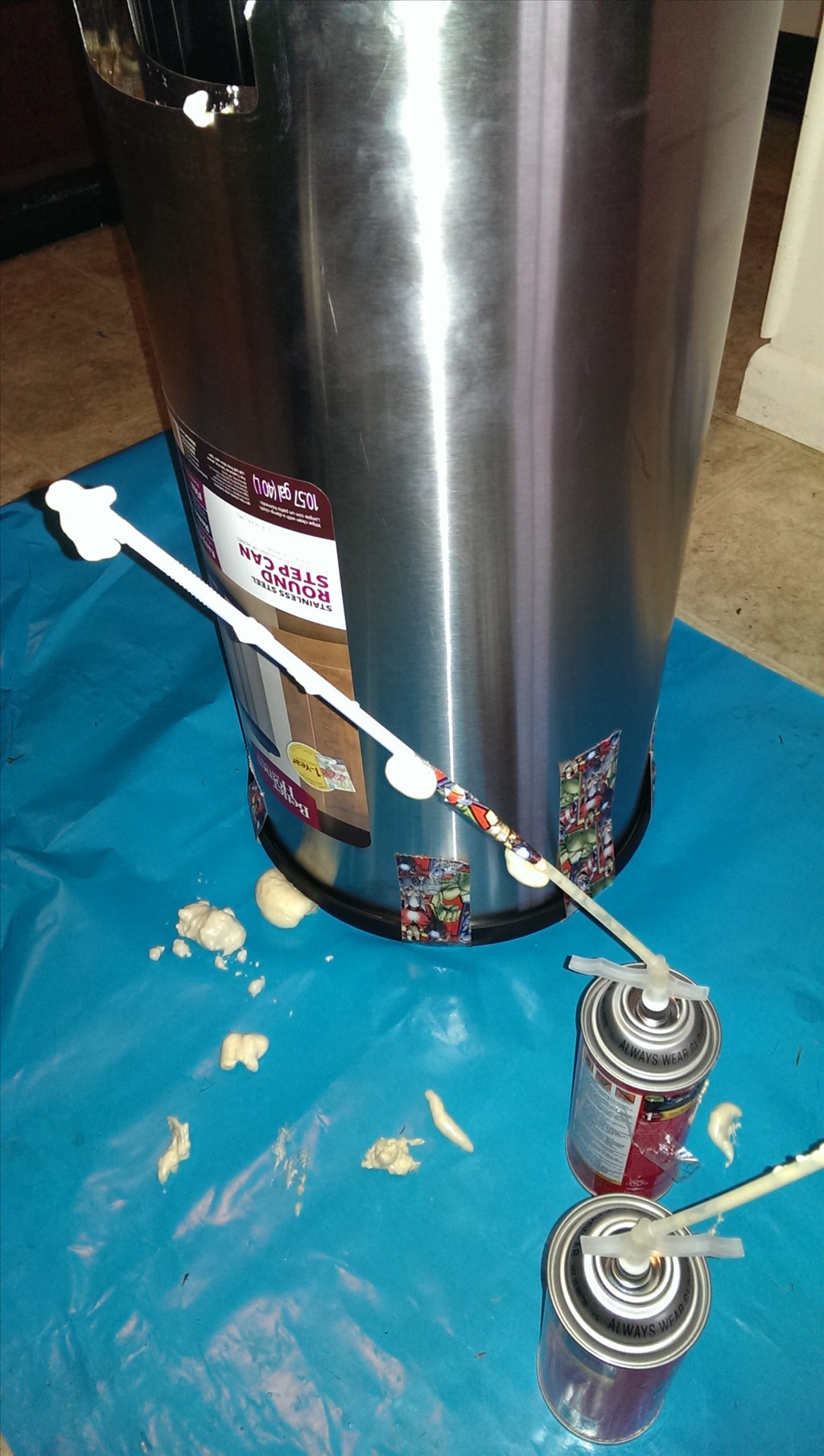
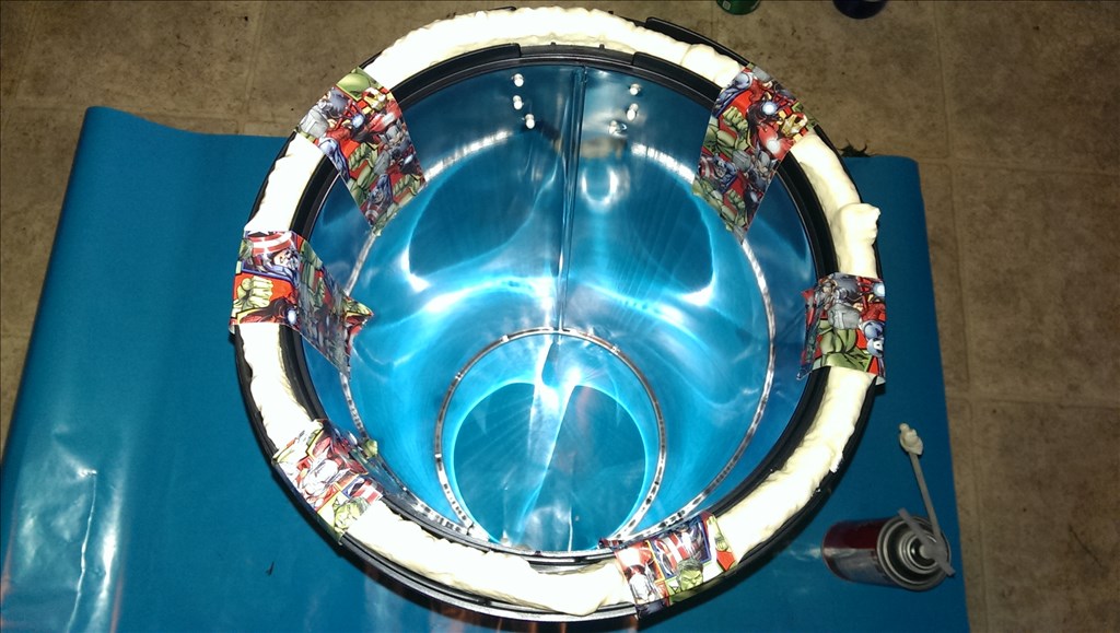
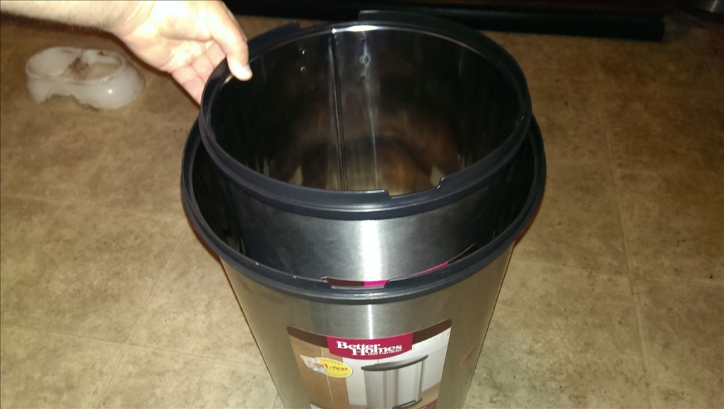
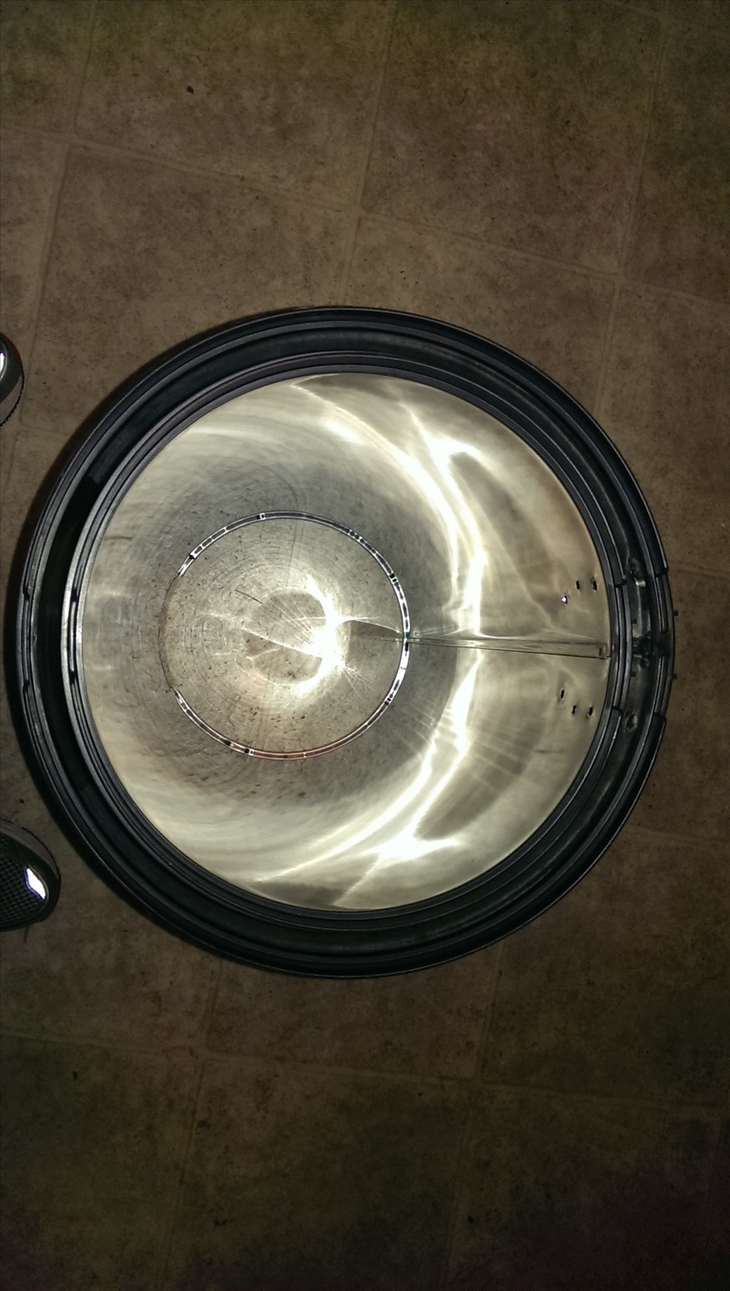
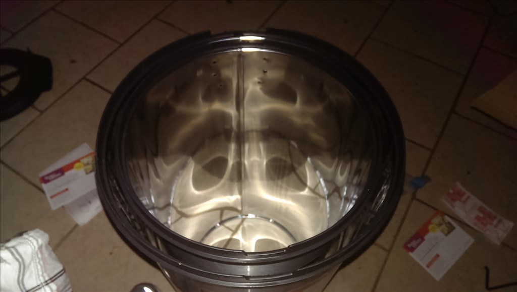
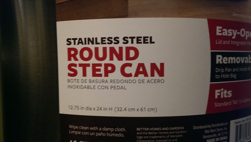
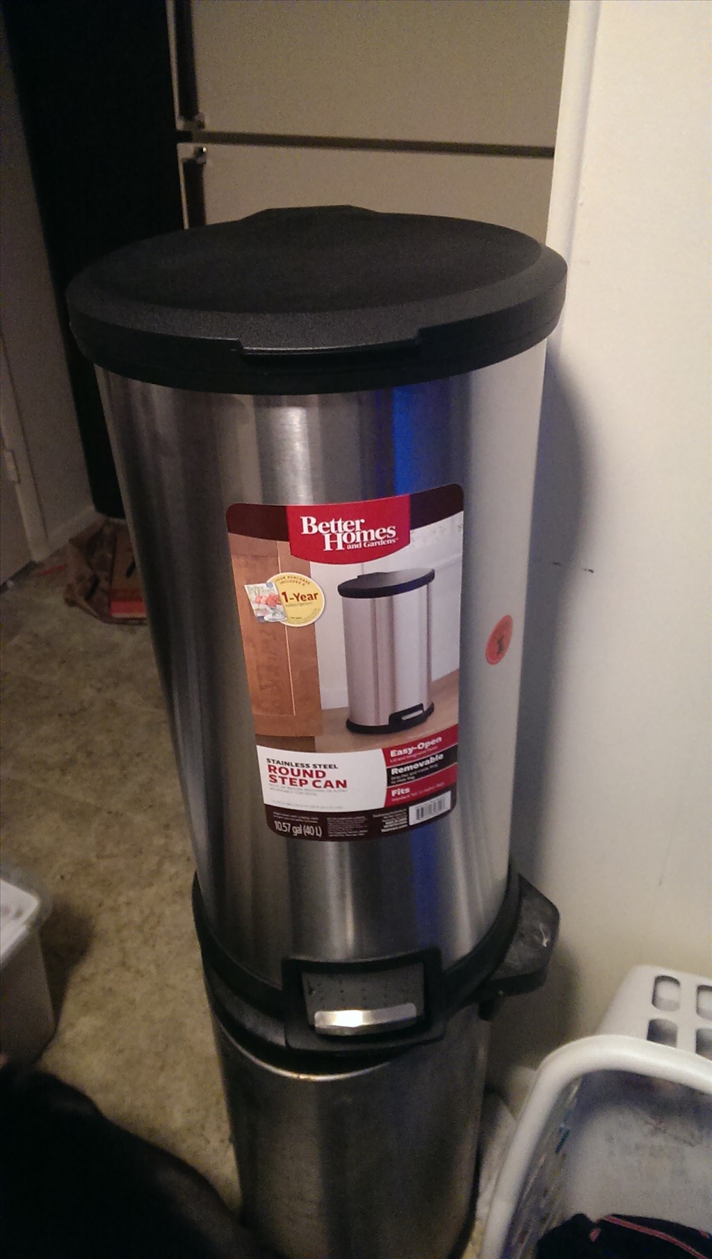
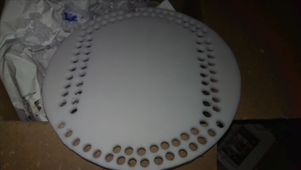
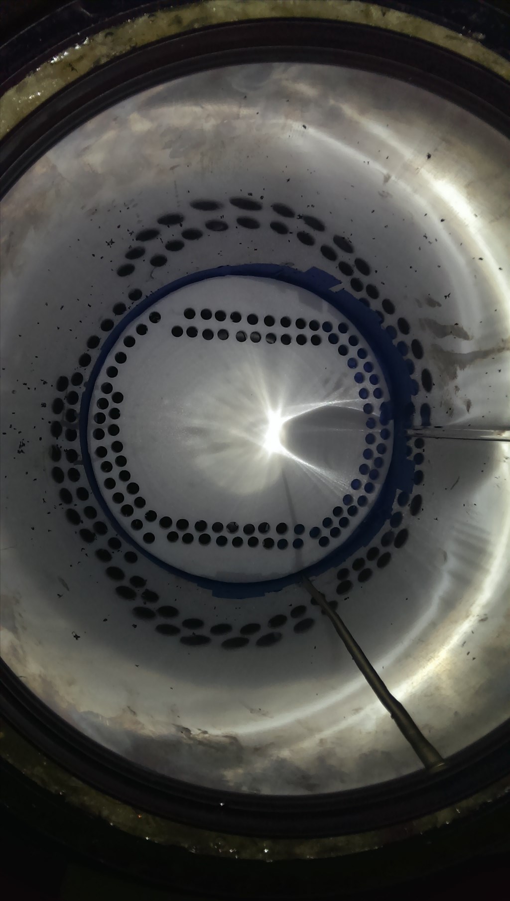
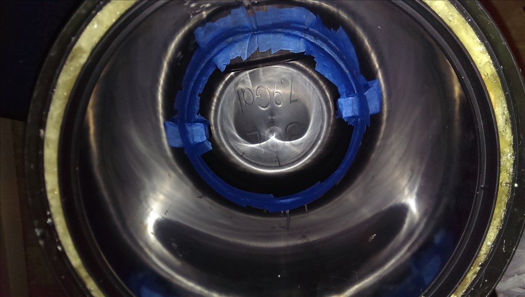
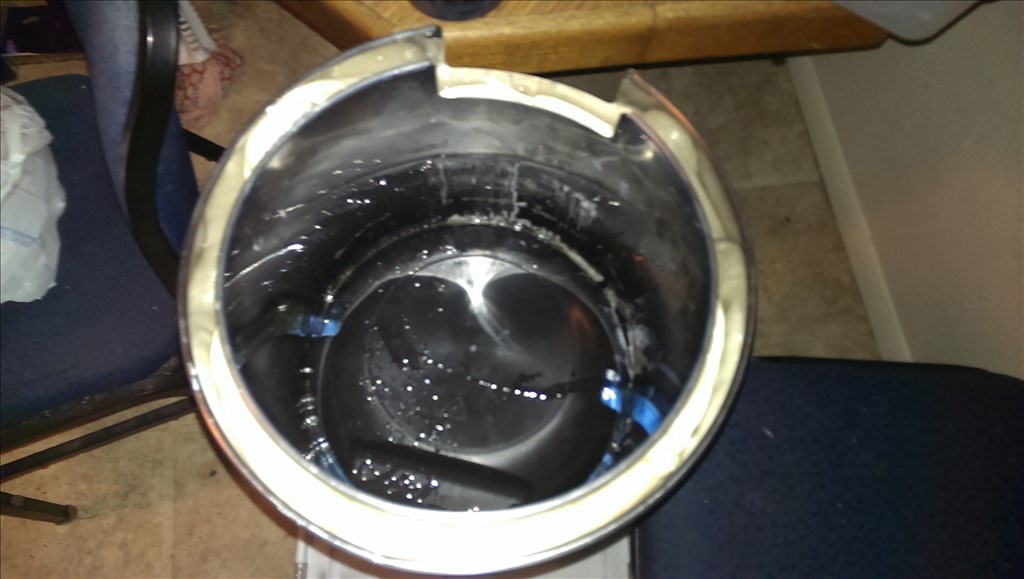
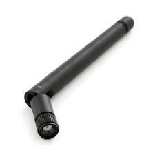
my cheap choice for a body, 39.99, I would have done plastic but i have a ocd obsession with it being round if possible. Since it is metal i already know there is the potential reception issue so i plan to have a external sma antenna mounted somewhere.
thanks PJ fast reply thats really cool
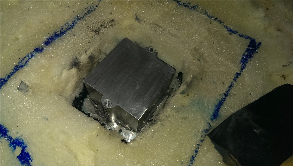
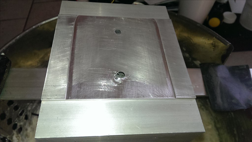
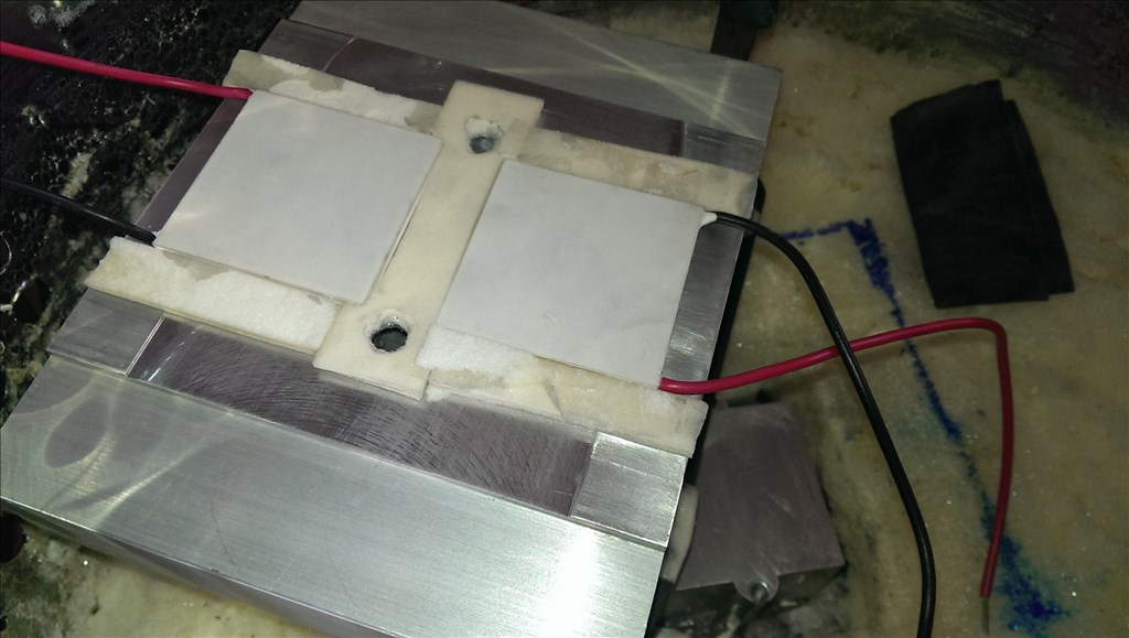
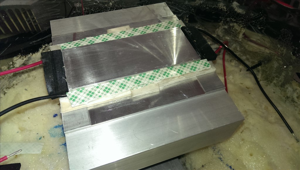
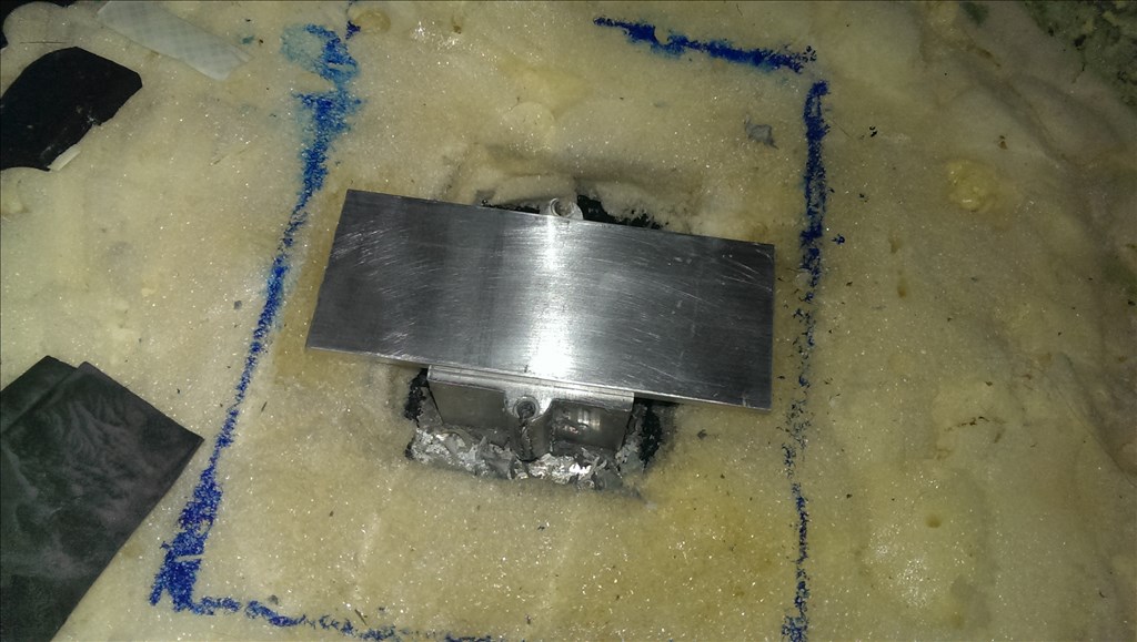
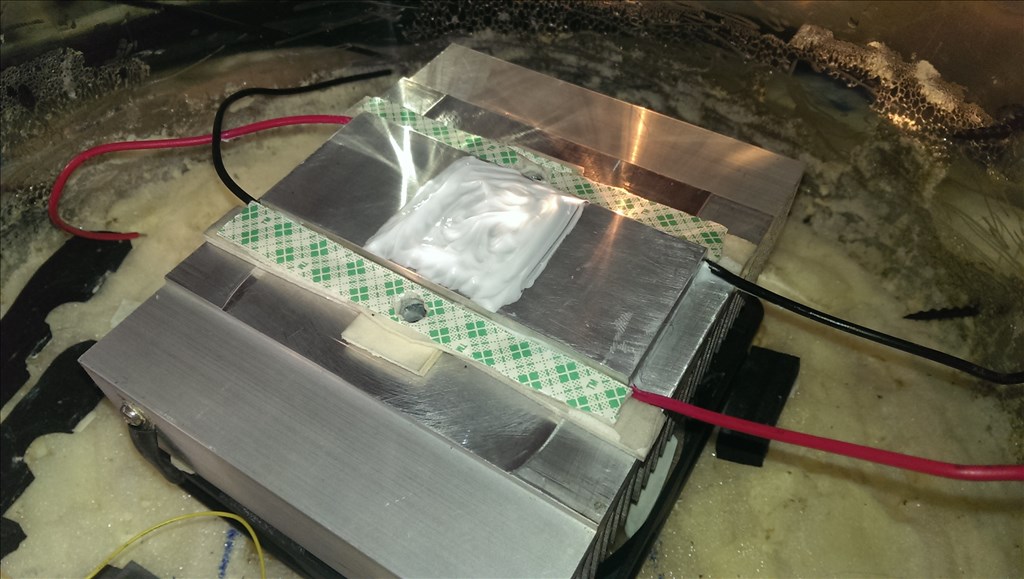
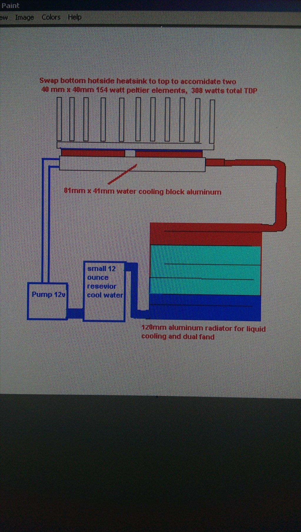
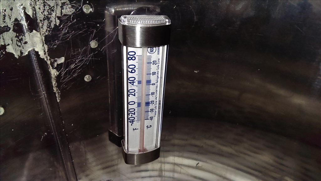
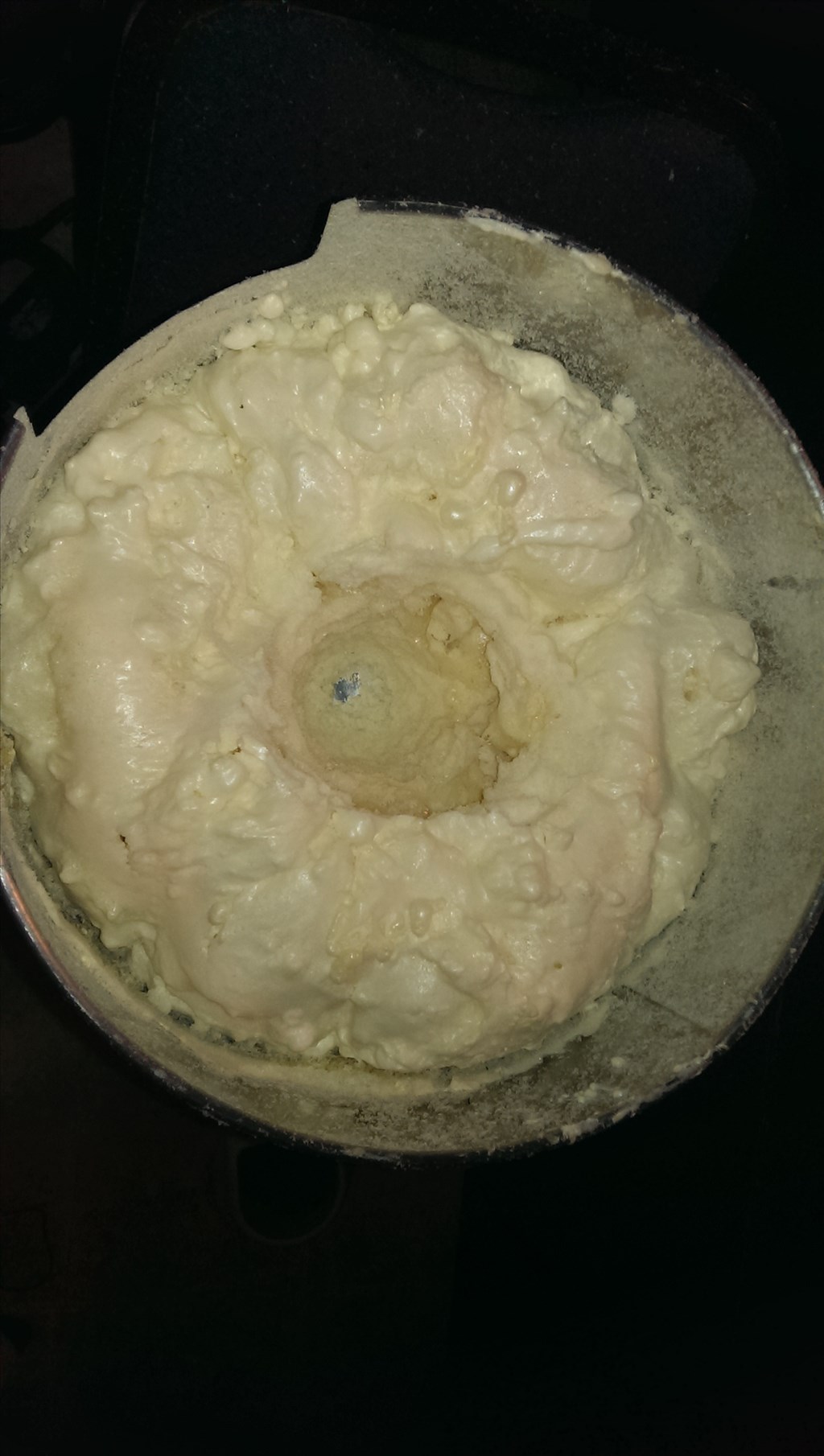
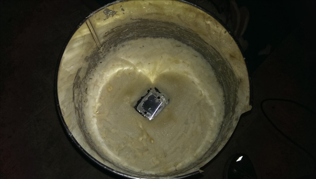
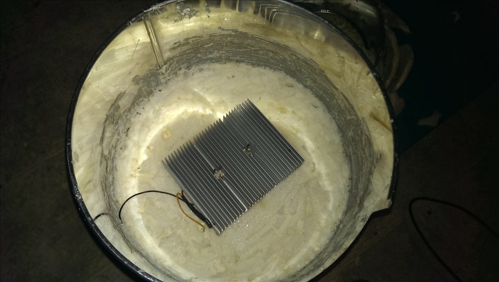
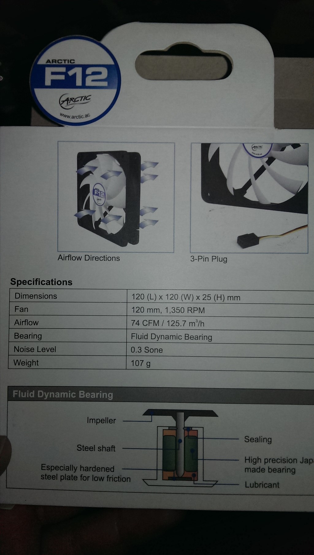
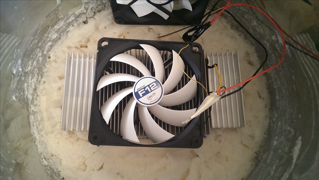
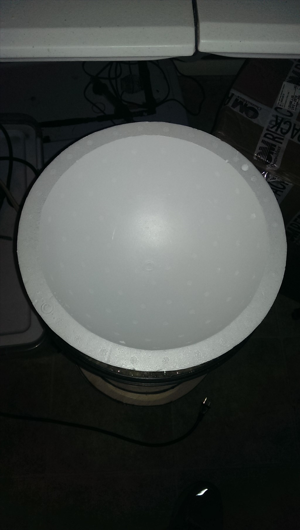
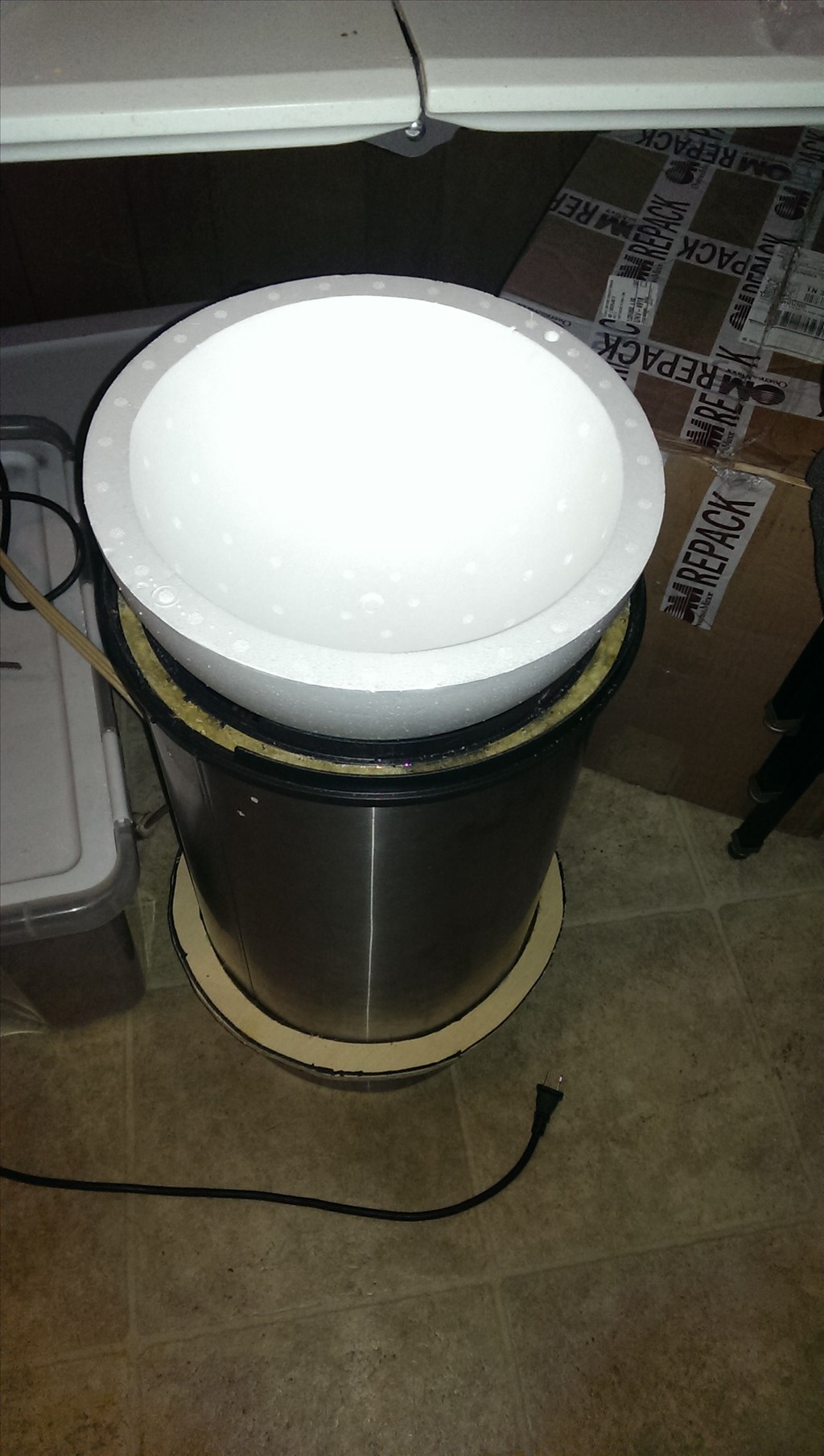
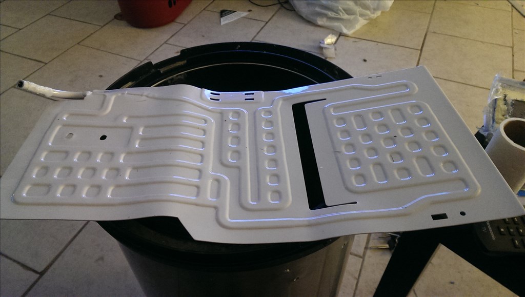
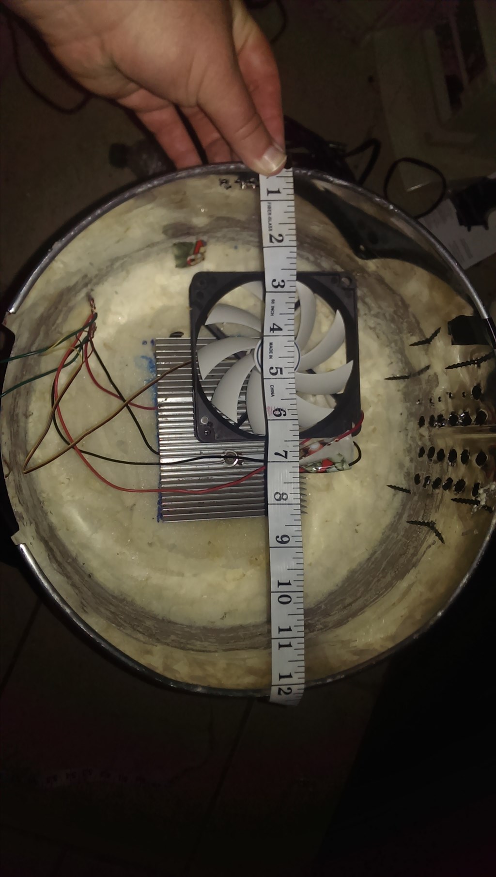
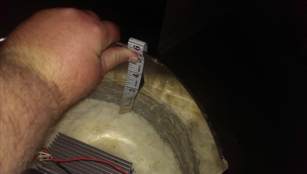
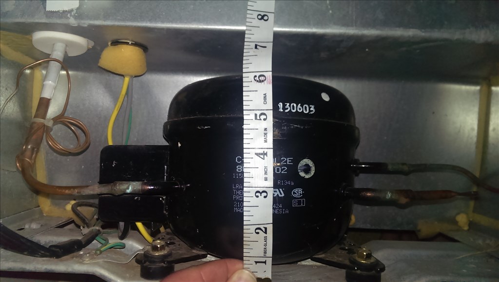
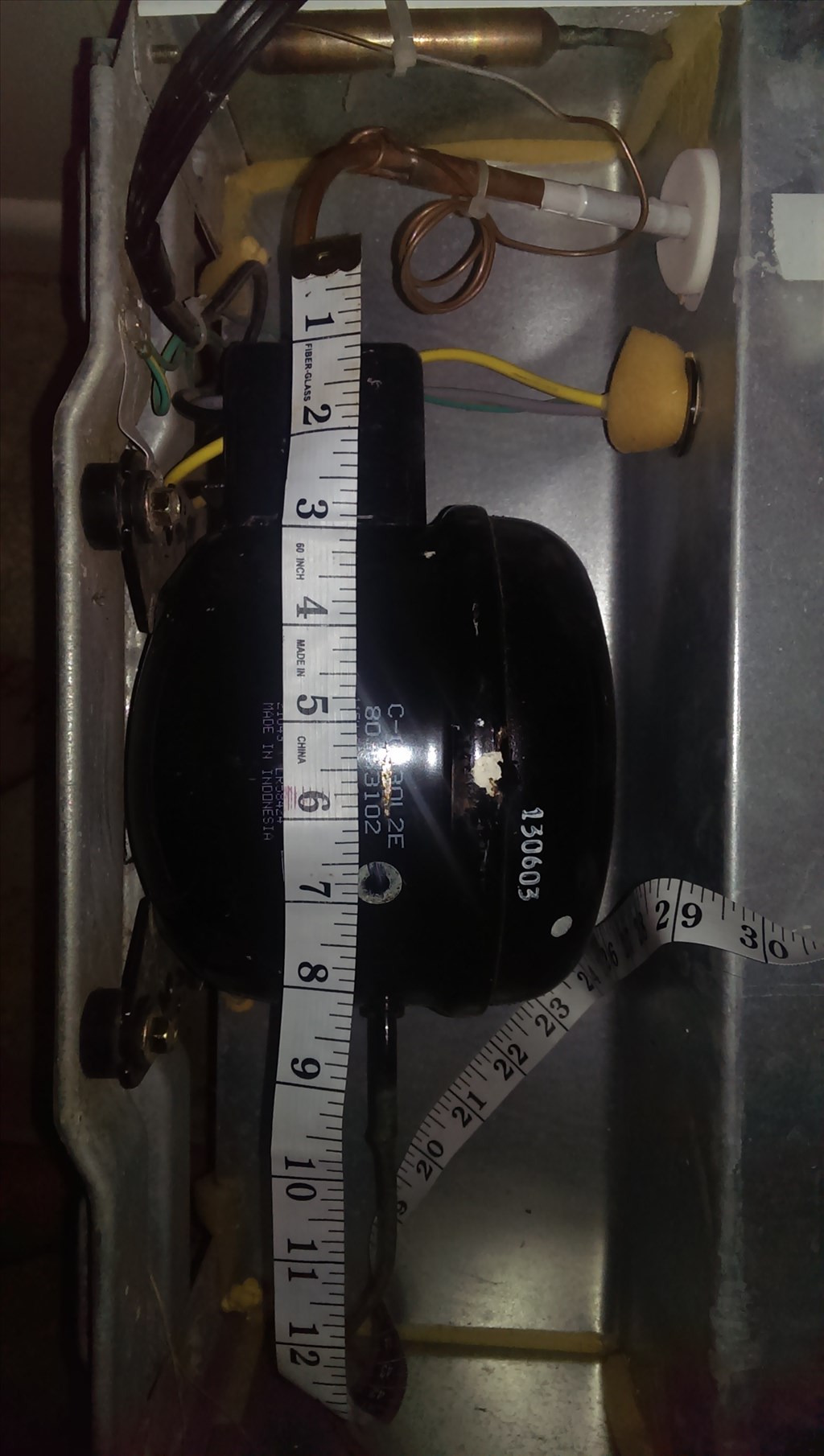
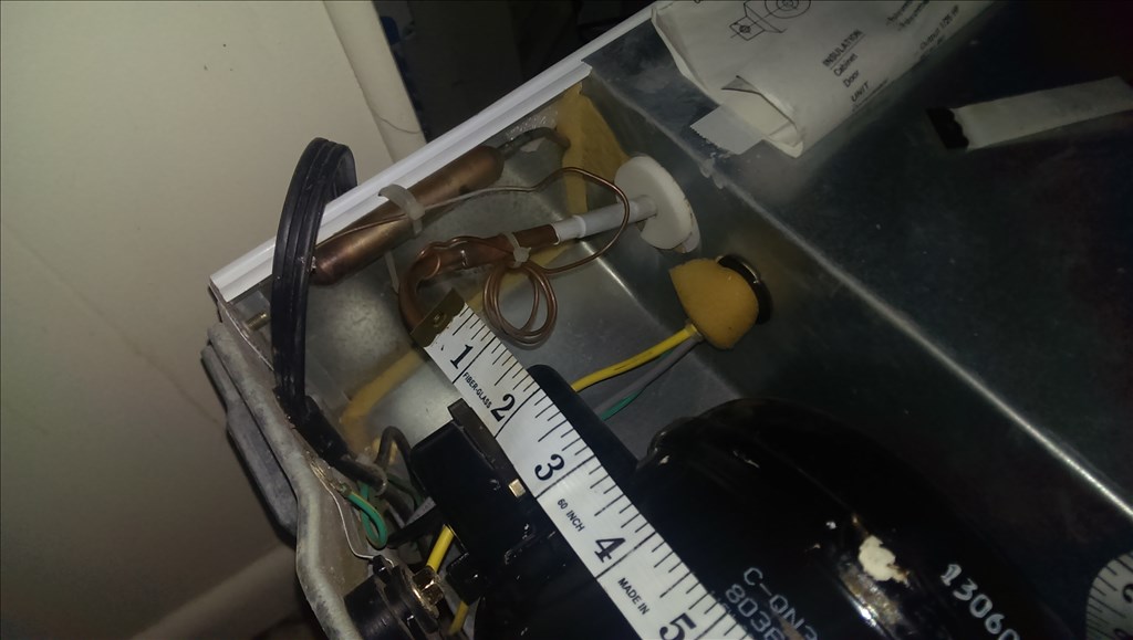
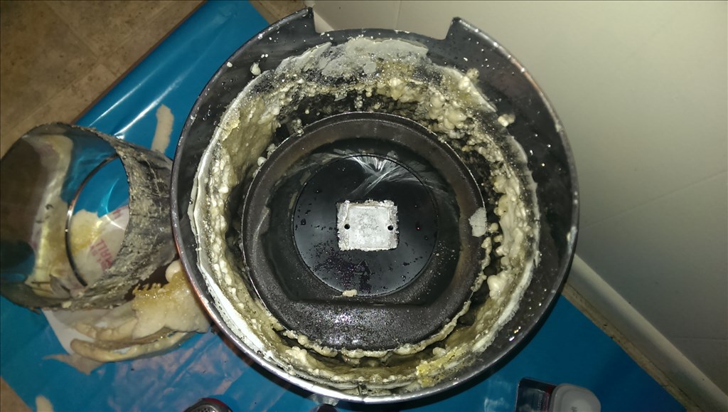
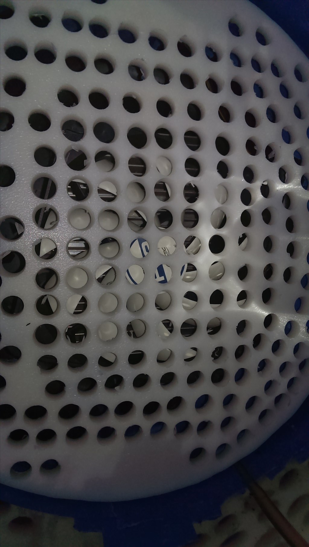
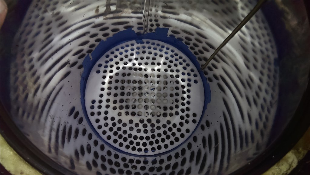
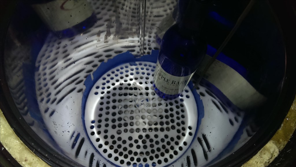
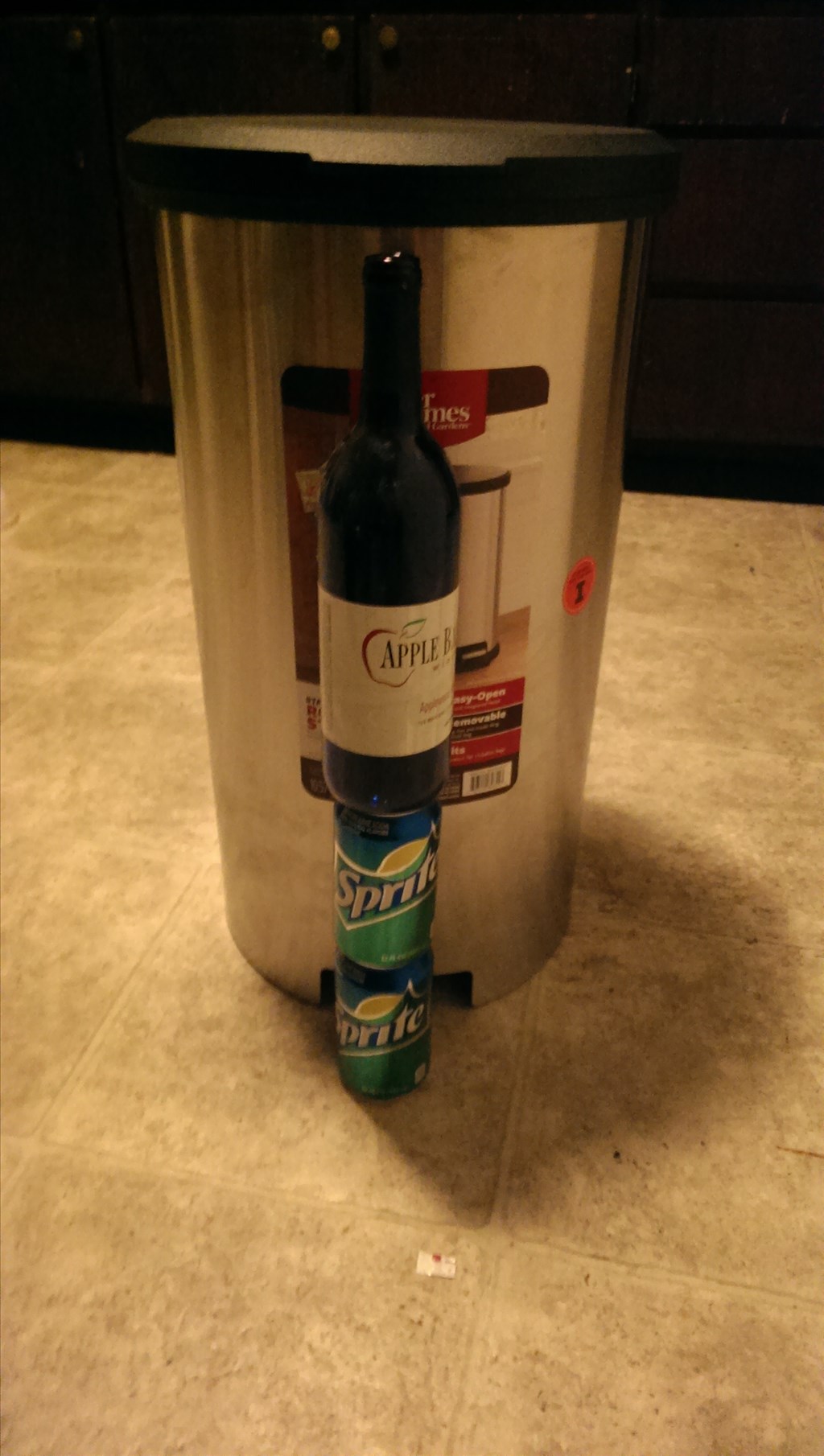
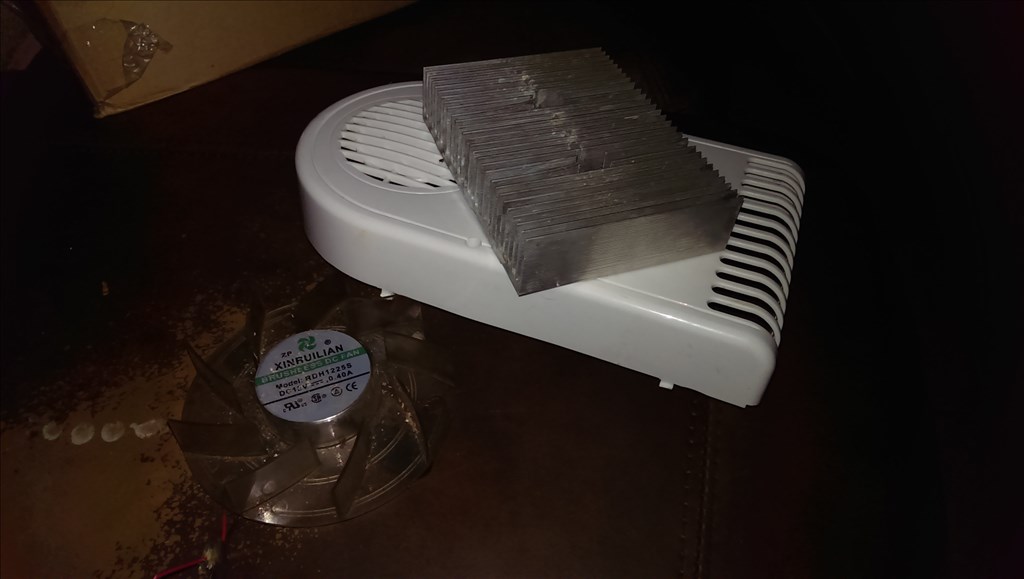
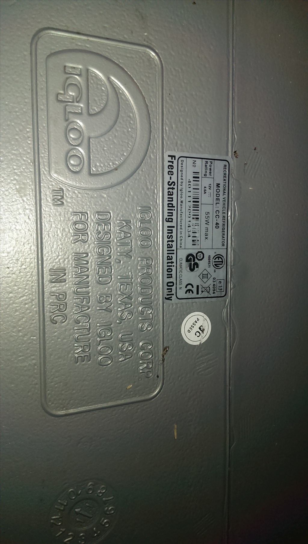
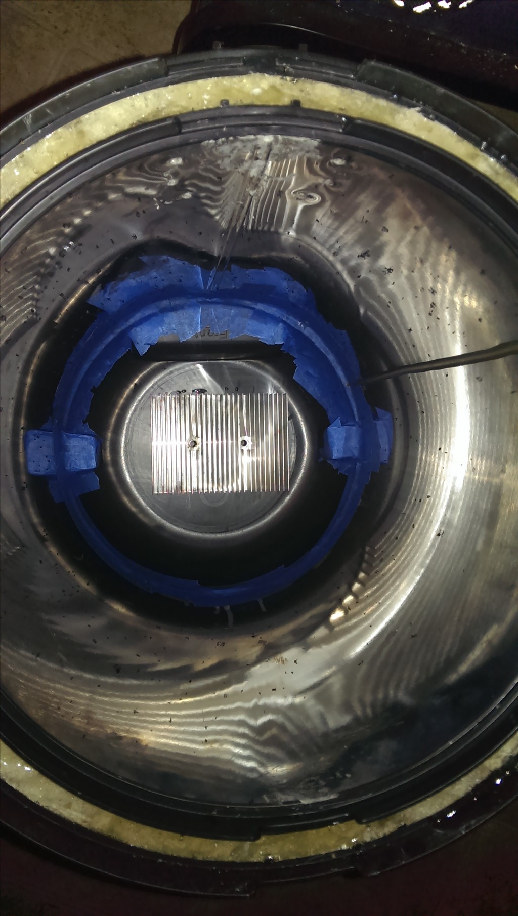
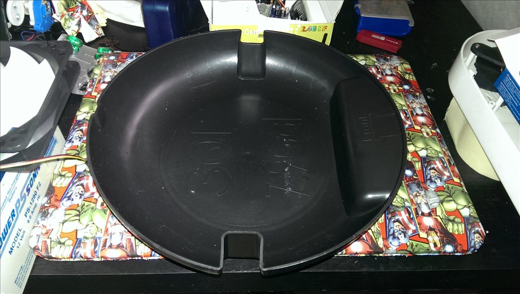
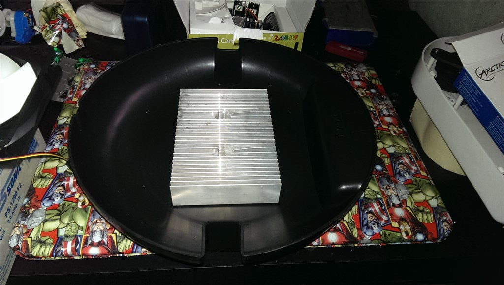
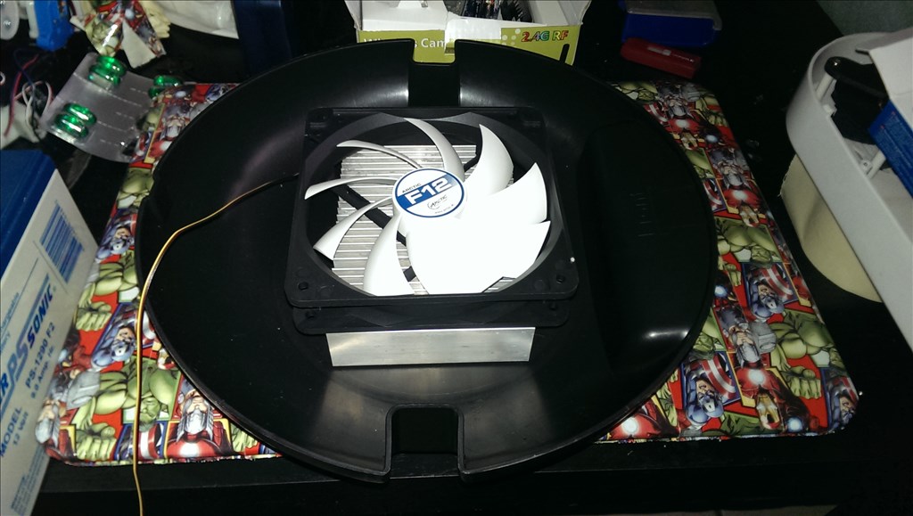
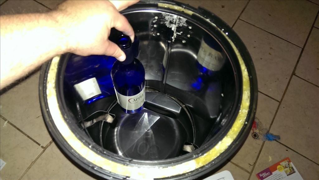
This is the main chiller unit, Igloo says it can chill 40 cans or 4 liters of liquid up to 40 degree below ambient temperature. The bottom larger sink is the hot side and top is the cool side. there is a large solid aluminum block that serves as a thermal pipe to move the heat from the cool side to the hot side . since the block is very thick i can insulate the area where the beverages will be. The Peltier unit is sandwiched on the hot side. Both already have fans that are blower style. Fans usually work much better when pulling than pushing into a heatsink. That being said I believe I will use some larger 120mm High performance PC fans to make sure the air flows nicely. Also PC fans are made with low sound options which is a pet peave of mine when building any project.
Anyone have ideas of hot to make this chilling unit better? suggestions ? thanks
https://www.igloocoolers.com/faq2 igloo facts page for the thermoelectric unit i came by at auction
Thermoelectric coolers are designed to cool contents as much as 40 degrees Fahrenheit below the room or outdoor operating temperature (e.g. If outdoor temperature is 75 degrees Fahrenheit, the thermoelectric cooler will cool the contents down to 35 degrees Fahrenheit).
Igloo Thermoelectric coolers are designed to operate between 48 to 60 watts (depending on model) and draw an average of 4.2 - 5.0 amps on a continuous basis.
if you want to buy one... https://www.westmarine.com/webapp/wcs/stores/servlet/Product_11151_10001_1193911_-1?ci_src=14110944&ci_sku=1193911&cid=sc_googlepla&device=c&network=g&matchtype=&gclid=CND345jE77gCFSYV7AoduwYAFQ#.UgRw4JLrxfg 179.99
I have the same Idea in mind for my personal robot, but wanted to stay away from the traditional omnibot shells , etc. So I was thinking of a Roomba Vacuum as a base, along with a strip water cooler fridge or trash can as the body. originally Stainless steel was my first option but than again making it as light as possible is my number priority so i drifted away from it. I am not going to start until the release of the new revolution board, so lots of time to brain storm
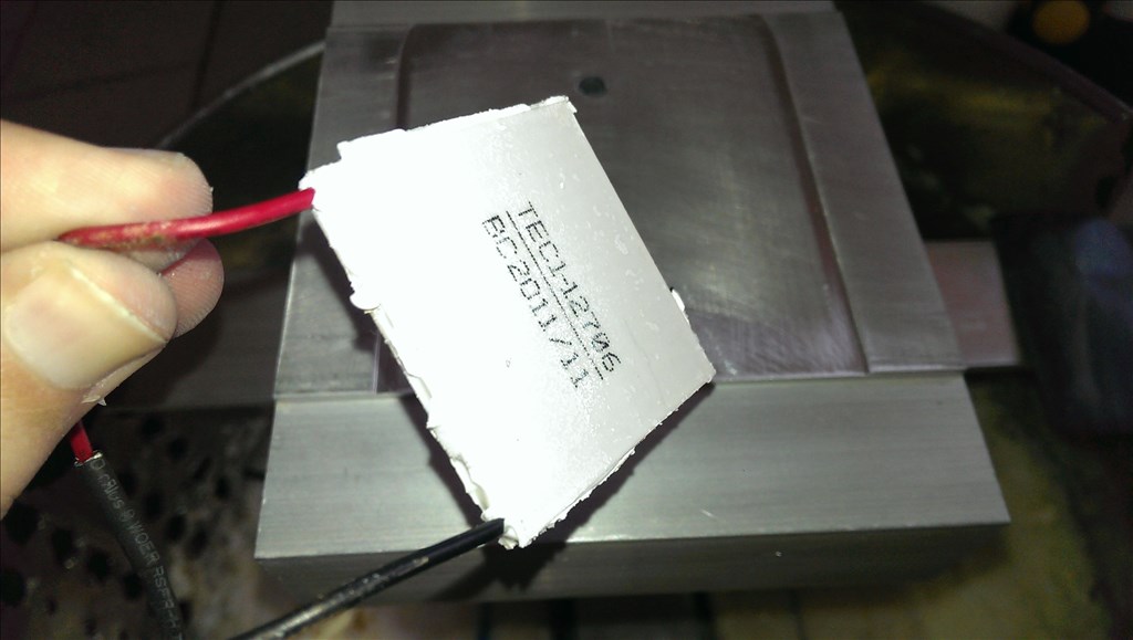
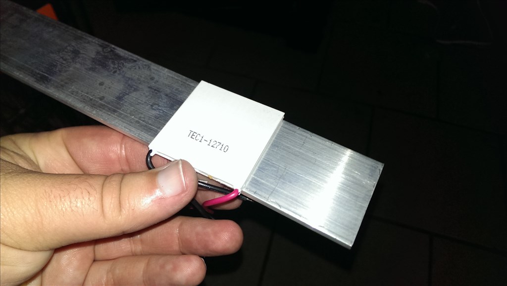
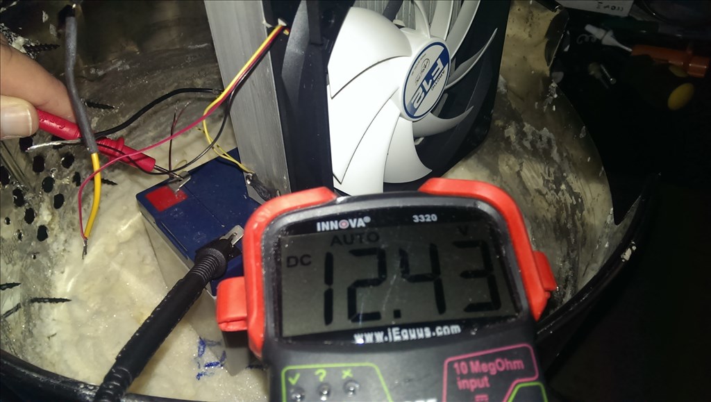
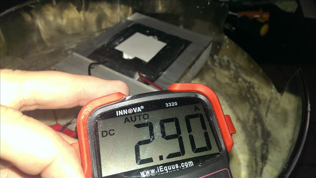
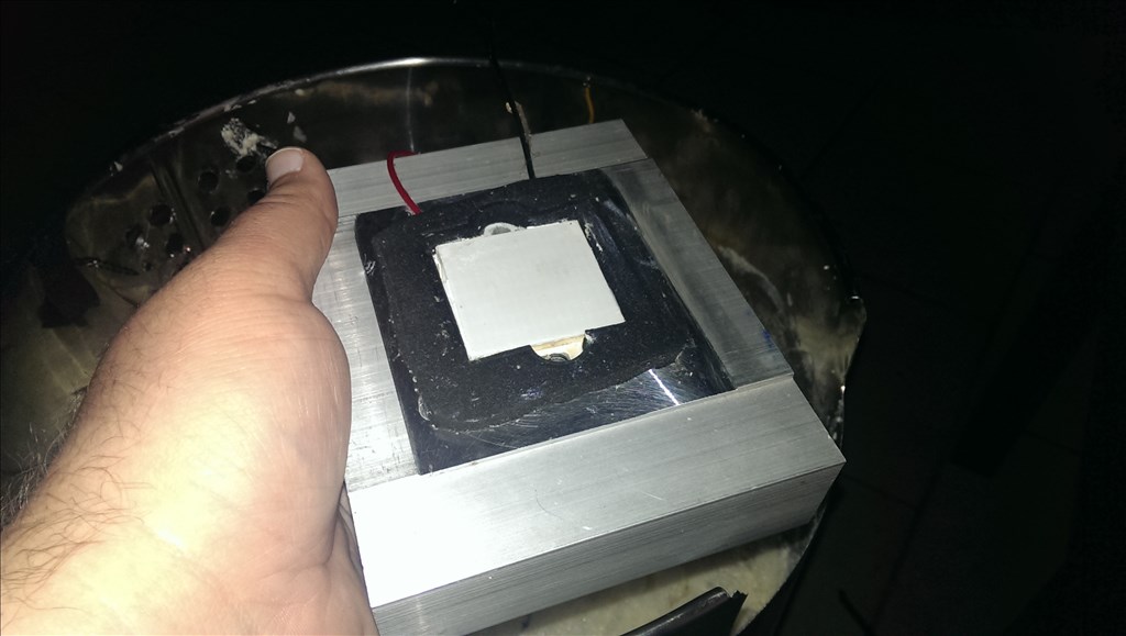
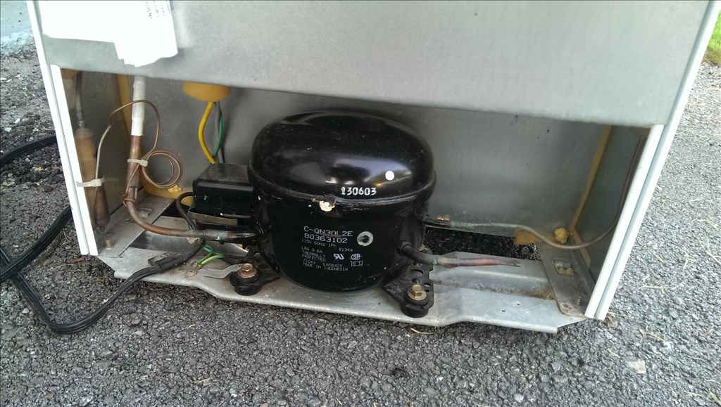
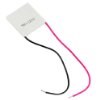
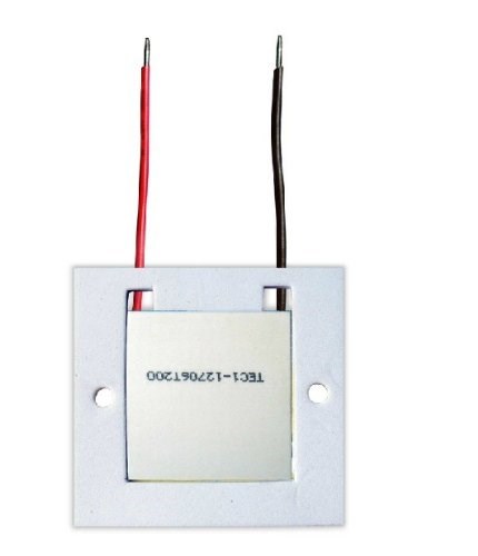
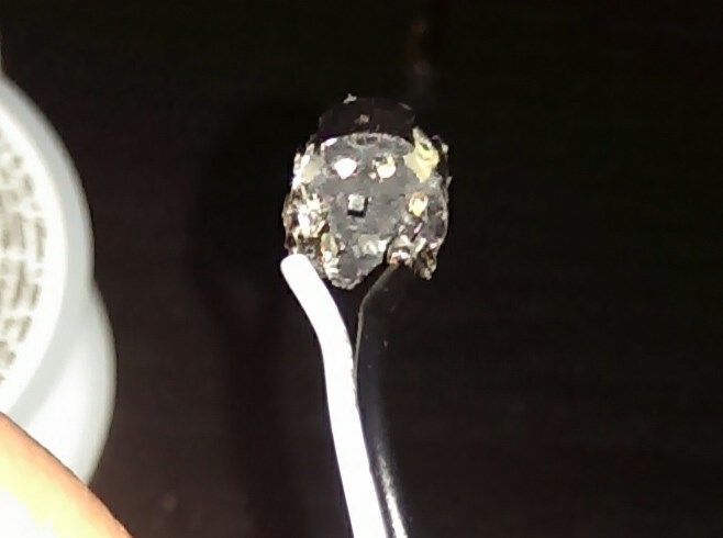
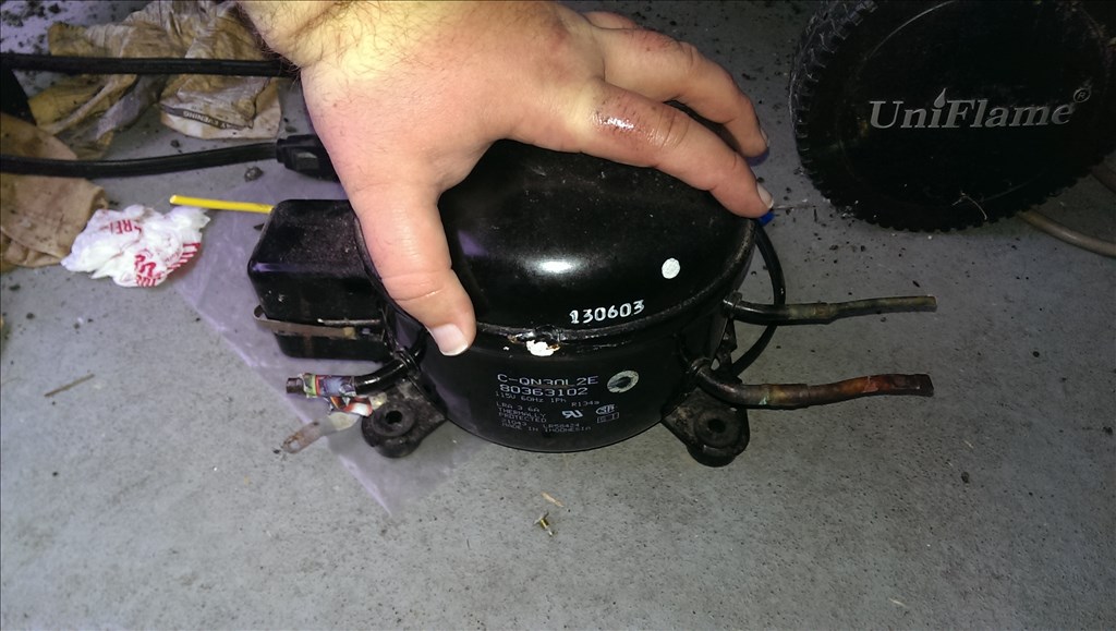
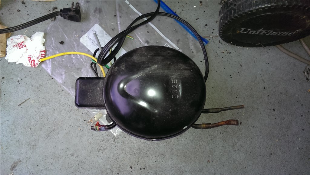
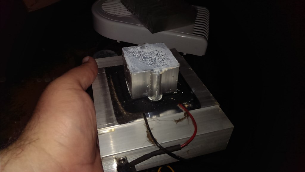
Since I bought my Peltier element and heat sinks from the auction I wanted to make sure it worked. I powered it up without fans. It took about 2 minutes for the hotside to warm up. It appears it will work but I'm still considering buying a higher power Peltier. This one is a 45w to 50 watt.