CMC206
USA
Asked
— Edited
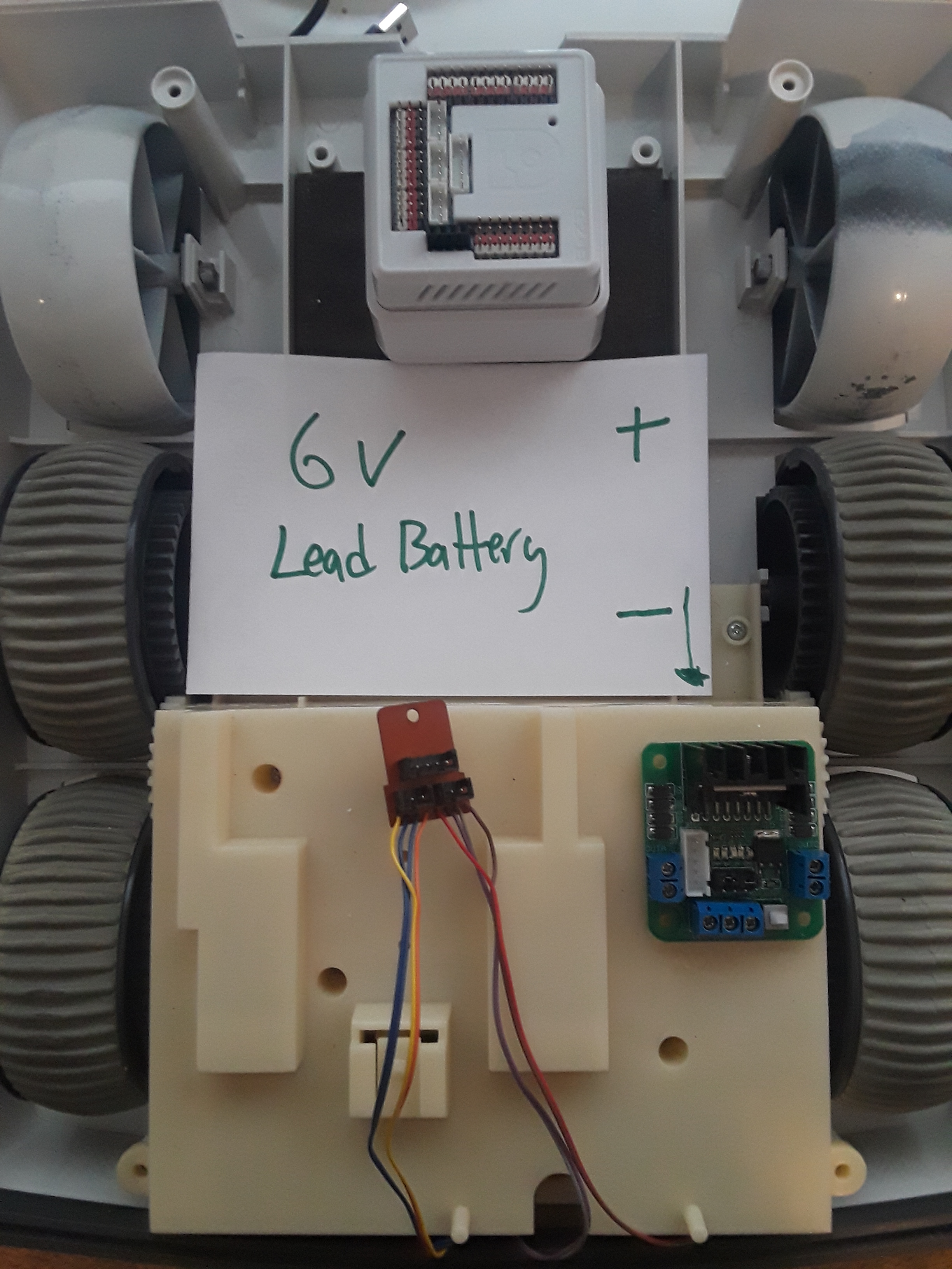
I have taken a couple of years off of this omnibot 2000 build. I kind of get stuck, frustrated and quit. Then every no and then I comeback and look at it again. I have watched a lot of the videos people/bot have recommended and I'm still stuck. Mostly this is because I'm not an electrical engineer...LOL I know how to take things apart and monkey with stuff. I can solder and follow instructions but this project has stalled. My main issue is that the videos go to fast and are not detailed enough for my limited knowledge. So here is where I'm at. How do I wire the hbridge to the ezb and battery and how do I wire the 8 motor wires to the hbridge? Here are a couple pictures to show what I have going. Thanks in advance for any advice.
Related Hardware (view all EZB hardware)

EZ-B V4
by EZ-Robot
EZ-B v4/2 robot controller: dual Cortex ARM, Wi-Fi, audio/video, 24 servo/digital ports, I2C/UART, camera and Synthiam ARC control for custom robots
Wi-Fi / USB
Servos
24
Camera
Audio
UART
3
I2C
ADC
8
Digital
24
Related Robot Skills (view all robot skills)

EZ-B V4 Info
by Synthiam
Displays EZ-B v4 internal temperature and battery voltage, shows built-in battery monitor and LiPo protection settings in Connection Control.
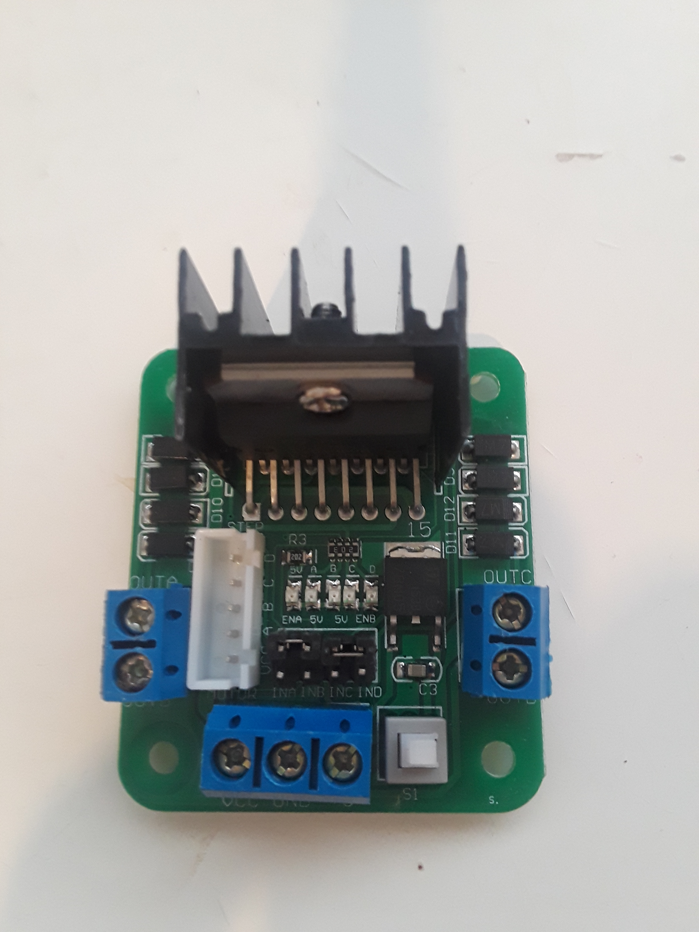
Dual Hbridge
by Synthiam
Two-channel Dual H-Bridge movement panel to control two DC motors (on/off) for forward, reverse, left, right via EZ-B digital ports; no PWM speed.

Did you see the diadram at this link,try it out and you will get it working but some wires may need to be switched around to get correct movements but it will get you really close. I see that some great links from Rich's tutorial are not working anymore and he was a big help for me at the start....h bridge
Use the pause button when watching videos
you selected hbridge when asking this question. However, the wiring diagram is in that manual page. Look at the hbridge manual page.
There aren’t 8 wires for the motor. There are 8 wires there but they aren’t all for the motor. You will have to look and see what wires are actually connected to the motor and which wires aren’t.
Only 4 wires are needed to connect to the hbridge. Red/Brown and Orange/Yellow. You can double check by tracing them to the motors. You will also need like 8 female to female jumper wires to connect the hbridge to the EZB. I just wired mine up like a week ago so feel free to ask any questions. Regarding the leds for the eyes. I used 6v blue leds soldered to 2 jumper cables. I ran a resistor between them and everything works great. Ill try to post some pictures for you when I get a chance. Hope this helps
Awesome! Thanks, Everyone! I will get back when I get something to happen! Please the more pics the merrier.
Would this work for my battery needs? I found it in my barn from an old RC car. Its barely used.
Yes that battery should work great. If you want the battery to last longer in the future buy a battery that has a bigger number where it showing 1800 mah ,find one that says 5000 for example and Lipo batteries can put out more power than a Nimh.
Hey everyone. It LIVES! I had an issue with the switch on the Hbridge. So I sprayed some wd40 on it and blew it out with air and now she is a rolling.
Sorry. Next dumb question.... How do I make him go faster? Is it my battery? He is Suuuuper Slow! I added the PWM and that didn't make a difference. It does work though I can make him even slower...LOL
Thanks again, everyone! This is the farthest I have got. Now I know with confidence I can buy another EZB v4 and Hbrigde for the other bot my son has already torn apart.
It’s slow because there are two gears in the gearbox of that robot. One is slower than the other. You have to open it up the gearbox and turn the gear shift motor that moves the gear manually by hand.
Or you can study the wiring schematic of the gear box and learn the third tiny motor that changes gearing.
Its easier just to move it by hand.