Asked — Edited
Resolved Resolved by Xuven!

Need Some Help /Wire Diagram To Go By

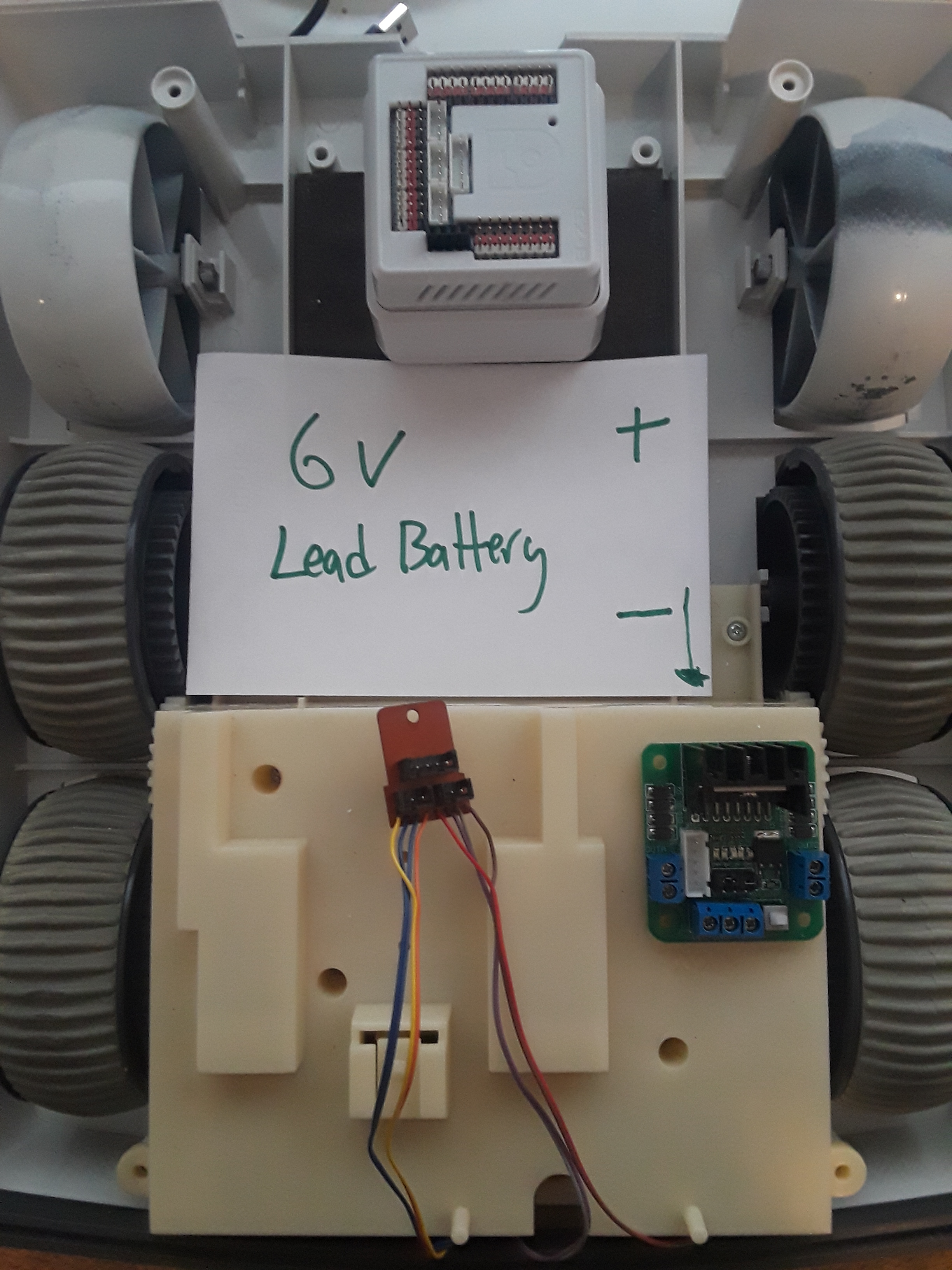
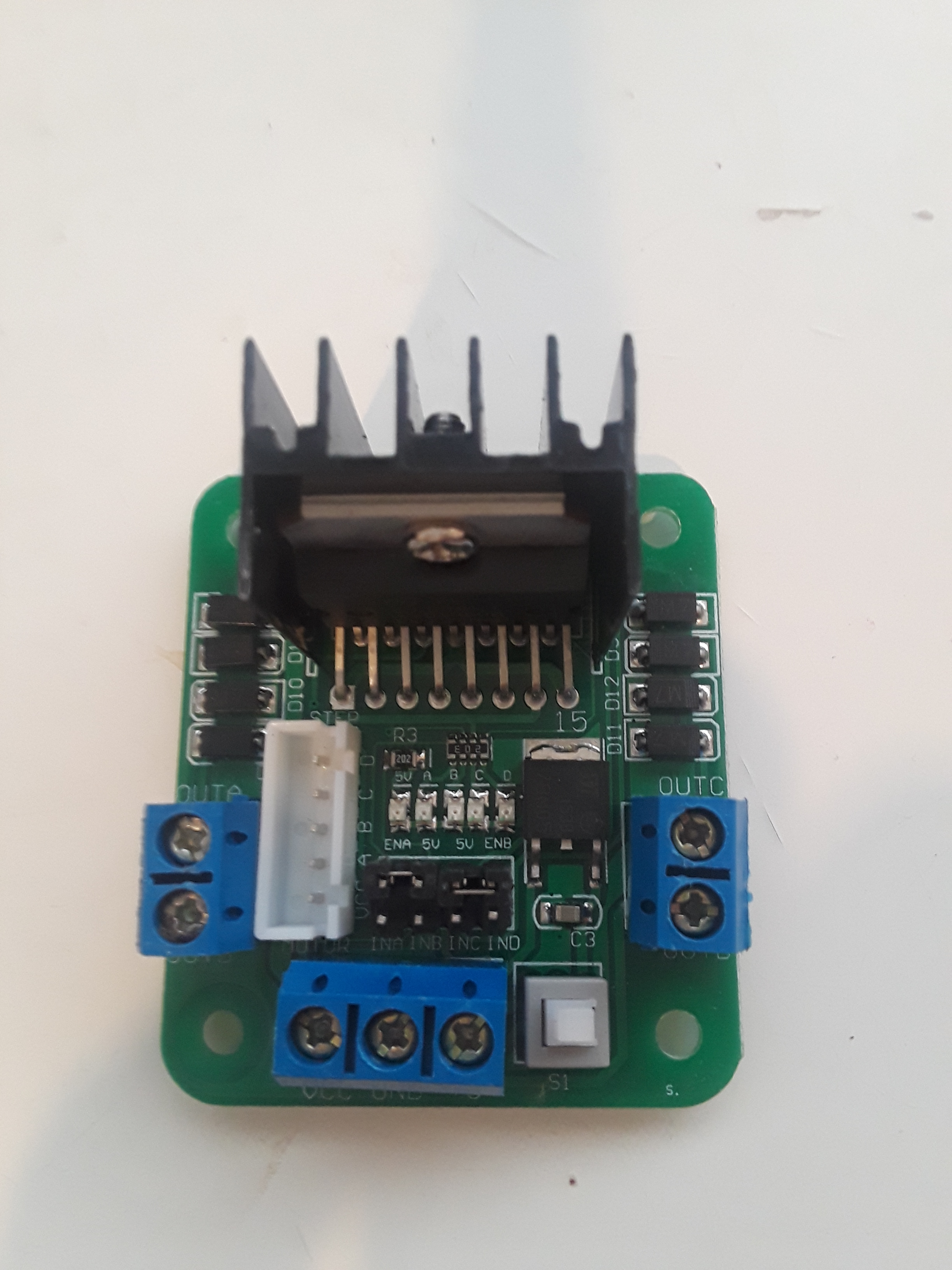
I have taken a couple of years off of this omnibot 2000 build. I kind of get stuck, frustrated and quit. Then every no and then I comeback and look at it again. I have watched a lot of the videos people/bot have recommended and I'm still stuck. Mostly this is because I'm not an electrical engineer...LOL I know how to take things apart and monkey with stuff. I can solder and follow instructions but this project has stalled. My main issue is that the videos go to fast and are not detailed enough for my limited knowledge. So here is where I'm at. How do I wire the hbridge to the ezb and battery and how do I wire the 8 motor wires to the hbridge? Here are a couple pictures to show what I have going. Thanks in advance for any advice.

User-inserted image

User-inserted image


Related Hardware EZ-B v4
Related Controls EZ-B v4 Info Dual HBridge

ARC Pro

Upgrade to ARC Pro

Your robot can be more than a simple automated machine with the power of ARC Pro!

#1  

Did you see the diadram at this link,try it out and you will get it working but some wires may need to be switched around to get correct movements but it will get you really close. I see that some great links from Rich's tutorial are not working anymore and he was a big help for me at the start....h bridge

PRO
Synthiam
#2  

Use the pause button when watching videos

you selected hbridge when asking this question. However, the wiring diagram is in that manual page. Look at the hbridge manual page.

There aren’t 8 wires for the motor. There are 8 wires there but they aren’t all for the motor. You will have to look and see what wires are actually connected to the motor and which wires aren’t.

#3  

Only 4 wires are needed to connect to the hbridge. Red/Brown and Orange/Yellow. You can double check by tracing them to the motors. You will also need like 8 female to female jumper wires to connect the hbridge to the EZB. I just wired mine up like a week ago so feel free to ask any questions. Regarding the leds for the eyes. I used 6v blue leds soldered to 2 jumper cables. I ran a resistor between them and everything works great. Ill try to post some pictures for you when I get a chance. Hope this helps

#4  

Awesome! Thanks, Everyone! I will get back when I get something to happen! Please the more pics the merrier.

#5  

Would this work for my battery needs? I found it in my barn from an old RC car. Its barely used.

User-inserted image

#6  

Yes that battery should work great. If you want the battery to last longer in the future buy a battery that has a bigger number where it showing 1800 mah ,find one that says 5000 for example and Lipo batteries can put out more power than a Nimh.

#7  

Hey everyone. It LIVES! I had an issue with the switch on the Hbridge. So I sprayed some wd40 on it and blew it out with air and now she is a rolling.

Sorry. Next dumb question.... How do I make him go faster? Is it my battery? He is Suuuuper Slow! I added the PWM and that didn't make a difference. It does work though I can make him even slower...LOL

Thanks again, everyone! This is the farthest I have got. Now I know with confidence I can buy another EZB v4 and Hbrigde for the other bot my son has already torn apart.

PRO
Synthiam
#8   — Edited

It’s slow because there are two gears in the gearbox of that robot. One is slower than the other. You have to open it up the gearbox and turn the gear shift motor that moves the gear manually by hand.

Or you can study the wiring schematic of the gear box and learn the third tiny motor that changes gearing.

Its easier just to move it by hand.

#9  

Wow. That's crazy. DJ you are a Genius! I shifted dude into second gear and now he mosies a lot better!

#10  

I got our omnibot moving really nice now. I have put the body back together as much as possible. I still have work to do with the eyes and getting some LEDs to blink is my next goal. Right now I decided to try the ultrasonic radar scanner. I have it hooked up right I'm assuming. It shows some red dots when things are in front of it. The other 2 collision avoidance and distance both show numbers going up and down so I'm assuming they are working as well. I have tried using all 3 together and each separately to no avail. When you put your hand in front of it the scanner stops moving. However, the bot doesn't stop or move or avoid anything. What could we be missing?

Thanks!

Thankks

User-inserted image

User-inserted image

PRO
Canada
#11  

Hi @CMC206,

A couple suggestions for you:

You can use the Ultrasonic "Collision Detection" control to stop the Omnibot if it detects an obstacle that meets the threshold value to you have setup in the control's settings. You will still have to initiate the move forward command, and then decide what you want it to do after it stops.

For the Ultrasonic "Distance" control, this is merely a readout of the distance value, it will be up to you to write a script using GetPing(D22, D23) to get the Ultrasonic distance value and decide what to do with it.

For the Ultrasonic "Radar" control, this is a readout of the distance value with a panning servo attached, it will be up to you to write a script using GetPing(D22, D23) to get the Ultrasonic distance value and decide what to do with it. You can also monitor where the servo is at with GetServo(D0) and make a decision based on where it's at.

For more information on these controls definitely click the '?' in the corner of each control or just search for the controls in the Product section

#12  

So I went back to the drawing board and realized I had more than a few pins and controls wrong. I worked on this all day today switching the pins and hbridge motor connections. When I pushed the forward button he would go backward. I figured it out when he went backward and the radar started working so I started flipping pins on the motor ports on the hbridge. After trying all different combinations on that with no success I reversed the 4 pin order on the hbridge and he went in the right direction and started to do collision avoidance. So now we are going to try and add in some voice control. We are still not sure how to go about the LEDs for his eyes. I was looking at the mblink leds but they are on backorder or 33 bucks a piece on Amazon. We need help with this. We would like to have the eyes blink every few seconds to give a life-like appearance and it doesn't matter if its just one color. We have tried hooking up LEDS and every time we do they burn out. If someone could point us in the right direction in VERY LEMANS TERMS ( what LEDS to buy, pins on the ezb to connect to, and what control to use) that would be great! We have searched all of the tutorials and manuals for this but still don't know what to do. We are pretty stoked to see him move about with a basic level of autonomy. Thanks again in advance for all of the suggestions and help. We are finally starting to achieve real progress on this project we started over 2 years ago and it is giving us the motivation to keep trying and go further.

Chris, Carson, OBA2K

#13  

You need to solder in a resistor on the led to avoid blowing it.

#15  

Never used those. I can only speak from experience using 5v blue leds with some resistors.

PRO
Belgium
#17  

User-inserted image

hey ptp is this what you are looking for?its the second pic.

PRO
USA
#18  

@Nomad 6R I don't see I2C (SDA, SCL) pins anywhere....

but CMC206 mentioned he plans to use I2C port and the RGB control.

To me looks a plain raw "neopixel" maybe CMC206 has more info from parallax ?

PRO
Belgium
#19  

ah the 3 ports on the ezbv4  is 12 c is ( sda, scl )thanks learn some.

#20  

No dice! HELP!!!

I have the three pins on the right soldered in. S1, +5, and GND. I tried putting it on a d10 an ADC0. Obviously, I have no idea what I'm doing but no light.

All of the tutorials have broken links or no video on youtube.  Looking at the picture above do you think it takes all 6 pins? I'm stumped.

If anyone has any advice on what pins to connect to and what control to add I would appreciate it. All I want to do is give this bot some eyes.

Thanks,

CMC

User-inserted image

User-inserted image

PRO
USA
#22  

@CMC206 I assumed when you mentioned I2C it was an I2C device.

Looking to the specs that is a neopixel and you cant connect directly to the EZB.

you need a neopixel controlller and or  an arduino or a parallax controller with custom firmware.

Search for neopixel to get an idea of what it is.

#23  

Thanks I will look in to that. I thought it was worth a shot because they were cheap.

#24  

The Parallax LEDs were a bust. I got some BlinkM LEDs and now I'm waiting for the camera extender and IC2 cables from EZ-Robot. In the meantime, I'm looking at putting a servo in the head to do just left to right movement. I'm going to put the camera in between the eyes to do movement tracking. What I'm looking for are any pics or advice on how to mount the servo in the Omnibot 2000 head. What parts to toss and what parts to cut and the alignment of the servo. From pausing DJ's video it's not quite enough and it looks like the head would be a weak point if someone was to pick it up by the head. I know there might not be a way around that but I want to start off in the right direction.

Thanks,

CMC

#25   — Edited

I used https://www.ebay.com/itm/Servo-Bracket-2-DOF-Short-Pan-Tilt-Sensor-Camera-Mount-Kit-Camera-Gimbal-MG996/152696892625?ssPageName=STRK%3AMEBIDX%3AIT&_trksid=p2057872.m2749.l2649. 2 servos for up/down and left/right.  Mounted the bracket on a piece of cardboard with a lot of hot glue. This is just a place holder til I i finish the 3d model for something more solid. I cut away part of the neck to try to keep it stock looking and still use the original hose. The top of the pan/tilt bracket is glued to the bottom of the head. I left enough of a gap to run the servo leads from the eyes down to the EZB

#26  

Thanks Xuven,

I just got the idea to use one of my Disc Golf mini markers to make a frame for the servo. What I was getting at is which way do I mount it? Sideways or front to back? Or does it matter? The ultrasonic servo I can set the radius that it can turn. I'm not sure if that applies to the motion tracking so I want to get it right before I break out the hot glue.  =)

User-inserted image

Front to back?

User-inserted image

Sideways?

User-inserted image

#27  

Sorry in advance for the poor images but it was hard to get a good picture. In the collar I have 2 layers of cardboard glued together.  In the middle is a cutout for one of the servos to sit in. The other servo sits sideways on top in the bracket linked above. It's really close to the opening in the collar and the top of the bracket is glued to the bottom of the head piece.

#30  

Perfect. Thank You!

#31  

That is pretty sweet! You convinced me to do the same thing. I got the 2 servo mounts on amazon for 14 bucks this morning. Do you have any other pics of the neck/ bottom of the head? I looked at the project pics on your profile and the video link you posted. That is giving me ideas on how to do it. Thanks again, my friend!

CMC

#32  

I had the same issue of finding pictures. I told myself I would take some and document along the way...never happened lol. If you can post a picture of the bottom and top of the collar. I should be able to use paint and draw something up to help you get started

#34  

Thanks, EZang60. I got the hbridge figured out. Tonight I got the I2C cables, camera extender and jumper cables set so I was able to connect the BlinkM leds to the eyes and mount the camera. I'm waiting for the servo mounts that Xuven suggested and I will get his head right. Baby steps but I'm happy with our progress. Here are some pics of the eyes working. Cheers! CMC

User-inserted image

User-inserted image

PRO
USA
#35  

Very good, have a nice week end

#36  

I had some difficulty doing the verticle servo so I just opted for the left-right movement only The good news is that I will be able to use the other servo in one of the arms. I was worried that I might burn out a servo or my kid might if we didn't hit an init script before starting. Even then every time I plug in the EZB the servos they all make a move to the right or a 0 position. So I did this repeatedly and that's when I got worried about the vertical servo that might get hung up. I figured that the left to right I won't have to worry.

User-inserted image

#38  

I got the same one as you linked. No worries. Moving on. Head is done and now I'm going to do an arm.