
PRO
afcorson
Australia
Asked
Do you know if ARC is compatible with a RoboClaw 2x30A Motor Controller? - see link: https://www.basicmicro.com/RoboClaw-2x30A-Motor-Controller_p_9.html
Related Hardware (view all EZB hardware)
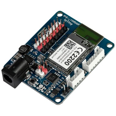
EZ-B Iotiny
by EZ-Robot
Control IoTiny with Synthiam ARC: 100MHz Cortex‑M4 Wi‑Fi IoT/robot controller-camera, servos, ADC, I2C and digital I/O for easy internet automation
Wi-Fi / USB
Servos
8
Camera
Audio
UART
✕
I2C
ADC
✕
Digital
✕

From the LIPO battery suppied with the JD - 7.5v
You have a wiring problem. You are lucky RoboClaw is a fine piece of hardware and software and can endure some user damage. I've damaged a few controllers due to fast browsing the manual, extra confidence or assuming specific behaviors.
you have 2 different power sources: Main battery Input: 6 to 34 VDC Logic Battery Input: 6 to 34 VDC
Logic battery is optional it's a nice feature to avoid losing the control when a brownout occurs. Is optional in your wiring i see you don't have one, you don't need to look for a setting to disable.
Your controller does not have the LB-MB switch so the controller switches automatically between Main & Logic.
The next important detail is Controller Logic Level RoboClaw uses a BEC (DC/DC) to convert the power source (Main or Logic Battery) to 5 volts, 5 volts is TTL level used for input or output pins. The manual says the control supports 5v or 3.3v that means roboclaw will accept 3.3v as High value input when transmitting the TTL voltage is still 5V. If you connect your Roboclaw TX to a 3.3 controller RX (e.g. Raspberry PI, Arduino DUE) you can damage the other controller. You don't need to worry EZB4 / IotTiny are 3.3v and 5v tolerant, that means they will communicate 3.3v and will tolerate 5V response.
This is your controller:
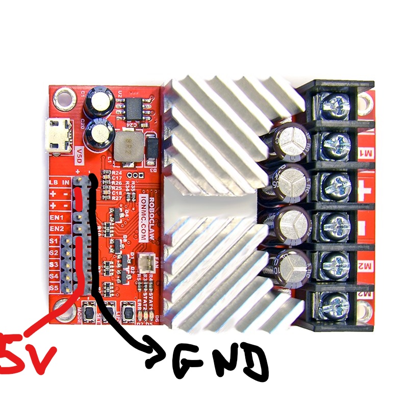
As documented in the manual those pins (red, black) carry 5v and GND. Your wiring is short-circuiting two different power sources 5v with 7.2v. You need to connect only the D5 e GND from the EZBLet's hope the controller is not damaged...
Most of what you have explained I was aware of, so thanks for reinforcing. Your last point though is the key one which I was not aware of, i.e. the short-circuiting of the 2 power sources. But can you clarify "connect only the D5 e GND from the EZB"? Do I not connect the 7.2v wire from the EZB? Just the ground and controlling wires?
Correct only the D5 and GND remove the middle wire red (EZB VCC 7.2v),
OK. Straight away this has cleared the error message and my Init script spins the motors. That's a great step forward. Next I will play around with a custom Movement Panel and see if I can control the motors. Thanks for identifying the problem.
I should add this vital information as well...
Quote: Because the Sabertooth Control (useable for Roboclaw) handles two motors with one 8 byte character, when operating in Simplified Serial mode, each motor has 7 bits of resolution. Sending a character between 1 and 127 will control motor 1. 1 is full reverse, 64 is stop and 127 is full forward. Sending a character between 128 and 255 will control motor 2. 128 is full reverse, 192 is stop and 255 is full forward. Character 0 (hex 0x00) is a special case. Sending this character will shut down both motors.
Motor 1 Reverse should be set as 1. Stop should be set as 64. Forward should be set as 127.
Motor 2 Reverse should be set as 128. Stop should be set as 192. Forward should be set as 255.
I agree with Alan. https://synthiam.com/Community/Questions/Robo-Claw-2x30-8968
@DJ you were correct
both Robotclaw and Sabertooth are rich controllers with a lot of features, I assumed the sabertooth control was specific for Sabertooth.
I just tested the control and checked the output:
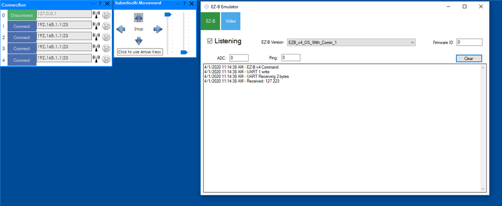
basically is the Simplified Serial mode post #14Simple and plain, no black magic, nothing specific.
I would add more information about Simple Serial Protocol and i would mention RoboClaw controllers
Sorry guys, I assumed something without checking the control.