
ed_eilers
Netherlands
Asked
— Edited
Help With Serial Bus Servo (Almost Dynamixel Protocol)
I would like to get some help on serial bus servo's that use almost the same protocol as dynamixel.
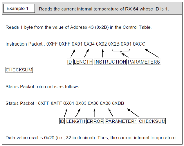
BUT all the dynamixel instruction packets and status packets start with:
0xFF 0xFF and then you get ID> Length> Instruction>Parameters>Checksum
like this
The servo's I want to use are Lobot LX-16A that use the same protocol with one difference: the packets start with 0x55 0x55 and then ID> Length> Instruction>Parameters>Checksum
so my servo's don't react on the dynamixelplugin How can I or someone change the 0xff too 0x55 in the plugin? Is it possible too get the source code for the plugin? or is there another solution? I can't afford real dynamixels and this seemed a good alternative
thanx in advance for your help

@DJ The servo's were the old ones not the HDD ones your correct.
I made an update to the checksum code in the plugin. Far as I can tell, it follows the datasheet 100%. Here's the latest plugin update: https://synthiam.com/redirect/legacy?table=plugin&id=252
Also, there's a bunch of reference to using the USB/TTL Debug servo Board. Which I cannot seem to find any documentation of - specifically no communication protocol documentation. Unless it uses the same communication protocol as the servos, in which case it "should" work.
I’ve ordered a few of these to test with. Thanks for adding another servo option!
@DJ, can you add the source code the download plugin page? Thanks.
I am trying the plugin to get to work, a warning if you connect to the uart do not connect VCC only TX RX and GND maybe I am wrong but i have fried a EZ-B v4 already.
I wil send later some pictures and a link with al the info i have got plus the arduino code that drives these servo's via the interface with is needed to make it work.
thanks for the effort so far
Yes - you cannot power a motor off the uart, silly goose
Regulated power in the ezb is absolutely NOT for motors or high current. There’s an amperage limit in the datasheet. Make sure you check the datasheet when building a custom robot.
I keep my common datasheets printed and taped to my wall for quick reference. Here’s the ezb datasheet: https://synthiam.com/Tutorials/Lesson/18
Regarding the Arduino setup - are you connecting the servos directly to the Arduino or using the usb/ttl board? I’m confused by this magical usb board because it’s referenced in their documentation and nink mentioned it as well. Maybe the plugin should be communicating with that board instead?
@DJ No I'm not that retarded well sometimes but no what I did was power the interface board and the EZ-B from the battery 7,4 volts so that drives the servo's and connected the hardware UART vcc from the EZ-B to the UART interface VCC plus TX RX and GND and that did killed my EZ-B stress.
I have been trying to get the plugin to work but On the hardware UART no joy and software UART TX->RX also nothing happens, the thing what i could not get right in EZ-B script was the adressing of the low and high byte:
#define GET_LOW_BYTE(A) (uint8_t)((A)) //Macro function get lower 8 bits of A #define GET_HIGH_BYTE(A) (uint8_t)((A) >> 8) //Macro function get higher 8 bits of A #define BYTE_TO_HW(A, B) ((((uint16_t)(A)) << 8) | (uint8_t)(B)) //put A as higher 8 bits B as lower 8 bits which amalgamated into 16 bits integer
#define LOBOT_SERVO_FRAME_HEADER 0x55 #define LOBOT_SERVO_MOVE_TIME_WRITE 1 #define LOBOT_SERVO_MOVE_TIME_READ 2 #define LOBOT_SERVO_MOVE_TIME_WAIT_WRITE 7 #define LOBOT_SERVO_MOVE_TIME_WAIT_READ 8 #define LOBOT_SERVO_MOVE_START 11 #define LOBOT_SERVO_MOVE_STOP 12 #define LOBOT_SERVO_ID_WRITE 13 #define LOBOT_SERVO_ID_READ 14 #define LOBOT_SERVO_ANGLE_OFFSET_ADJUST 17 #define LOBOT_SERVO_ANGLE_OFFSET_WRITE 18 #define LOBOT_SERVO_ANGLE_OFFSET_READ 19 #define LOBOT_SERVO_ANGLE_LIMIT_WRITE 20 #define LOBOT_SERVO_ANGLE_LIMIT_READ 21 #define LOBOT_SERVO_VIN_LIMIT_WRITE 22 #define LOBOT_SERVO_VIN_LIMIT_READ 23 #define LOBOT_SERVO_TEMP_MAX_LIMIT_WRITE 24 #define LOBOT_SERVO_TEMP_MAX_LIMIT_READ 25 #define LOBOT_SERVO_TEMP_READ 26 #define LOBOT_SERVO_VIN_READ 27 #define LOBOT_SERVO_POS_READ 28 #define LOBOT_SERVO_OR_MOTOR_MODE_WRITE 29 #define LOBOT_SERVO_OR_MOTOR_MODE_READ 30 #define LOBOT_SERVO_LOAD_OR_UNLOAD_WRITE 31 #define LOBOT_SERVO_LOAD_OR_UNLOAD_READ 32 #define LOBOT_SERVO_LED_CTRL_WRITE 33 #define LOBOT_SERVO_LED_CTRL_READ 34 #define LOBOT_SERVO_LED_ERROR_WRITE 35 #define LOBOT_SERVO_LED_ERROR_READ 36
//#define LOBOT_DEBUG 1 /Debug i1/4print debug value/
byte LobotCheckSum(byte buf[]) { byte i; uint16_t temp = 0; for (i = 2; i < buf[3] + 2; i++) { temp += buf[i]; } temp = ~temp; i = (byte)temp; return i; }
void LobotSerialServoMove(HardwareSerial &SerialX, uint8_t id, int16_t position, uint16_t time) { byte buf[10]; if(position < 0) position = 0; if(position > 1000) position = 1000; buf[0] = buf[1] = LOBOT_SERVO_FRAME_HEADER; buf[2] = id; buf[3] = 7; buf[4] = LOBOT_SERVO_MOVE_TIME_WRITE; buf[5] = GET_LOW_BYTE(position); buf[6] = GET_HIGH_BYTE(position); buf[7] = GET_LOW_BYTE(time); buf[8] = GET_HIGH_BYTE(time); buf[9] = LobotCheckSum(buf); SerialX.write(buf, 10); }
void setup() { // put your setup code here, to run once: Serial.begin(115200); delay(1000); }
#define ID1 1 #define ID2 2
void loop() { // put your main code here, to run repeatedly: LobotSerialServoMove(Serial, ID1, 100, 500); LobotSerialServoMove(Serial, ID2, 500, 500); delay(1000); LobotSerialServoMove(Serial, ID1, 500, 500); LobotSerialServoMove(Serial, ID2, 600, 500); delay(1000); LobotSerialServoMove(Serial, ID1, 900, 500); LobotSerialServoMove(Serial, ID2, 700, 500); delay(1000); LobotSerialServoMove(Serial, ID1, 500, 500); LobotSerialServoMove(Serial, ID2, 600, 500); delay(1000); }
So the value that you put in these lines:
LobotSerialServoMove(Serial, ID1, 100here, 500); LobotSerialServoMove(Serial, ID2, 500here, 500);
will make the servo move from 0-1000 0 deg to 240 deg the id is the servo you want to move and the last value is the speed