
smiller29
USA
Asked
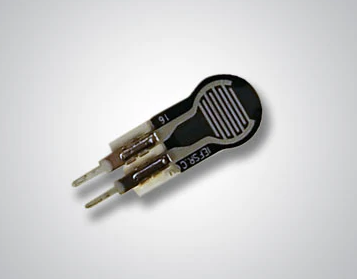
FSR 400 Force Sensing Resistors To The EZB4?
Now I have another question for you Jeremie.
I need to know if you can tell me how I can attach there FSR 400 Force Sensing Resistors to the EZB4 for finger touch sensors?
The FSR 400 short-tail model is a single-zone Force Sensing Resistor optimized to use human touch to control devices for use in automotive electronics, medical systems, and industrial and robotics applications. FSRs are two-wire devices. They are robust polymer thick film (PTF) sensors that exhibit a decrease in resistance with increase in force applied to the surface of the sensor. This device has a 5.6 mm diameter active area and is available in 4 connection options.
Related Hardware (view all EZB hardware)

EZ-B V4
by EZ-Robot
EZ-B v4/2 robot controller: dual Cortex ARM, Wi-Fi, audio/video, 24 servo/digital ports, I2C/UART, camera and Synthiam ARC control for custom robots
Wi-Fi / USB
Servos
24
Camera
Audio
UART
3
I2C
ADC
8
Digital
24

There are several types of sensors that can be used to measure force or pressure accurately. Here are a few options:
Load Cells: Load cells are highly accurate and can measure both compressive and tensile forces. They work by measuring the strain (deformation) in the load cell when a force is applied. However, they can be relatively expensive and may require additional hardware (like a signal amplifier) to read the output.
Piezoelectric Sensors: These sensors generate an electric charge in response to applied mechanical stress. They are often used in dynamic force measurements as they can respond very quickly to changes in force. However, they are not as suitable for static force measurements as the signal can drift over time.
Capacitive Force Sensors: These sensors work by measuring changes in capacitance caused by the deformation of the sensor when a force is applied. They can be very sensitive and are often used in touch-sensitive applications. However, they can be affected by changes in temperature and humidity.
Pressure Sensors: These sensors measure the pressure exerted on a surface. They come in a variety of types, including piezoresistive, capacitive, and optical, each with their own advantages and disadvantages.
The choice of sensor will depend on your specific requirements, including the range of forces you need to measure, the accuracy required, the environmental conditions, and your budget. Always refer to the datasheet of the sensor for precise information on how to use it.
@DJ /@Athena, Thank you for pointing out Hall effect current sensors I did not know anything about these devices until now. These could be a much better option for my design. I am trying to develop a finger using the below geared motors and taking a servo control board and pot and add them for position control along with either the FSR or Hall effect sensor.
That sounds like a great plan! The Hall effect current sensors can indeed be a good option for monitoring the current consumption of your geared motors. This can provide valuable feedback about the load on the motors, which can be used to control the grip strength of your robot's fingers.
As for using a servo control board and potentiometer for position control, that's a common and effective approach. The potentiometer can provide feedback about the position of the motor, and the servo control board can use this feedback to adjust the motor's position as needed.
Remember, when integrating these components, it's important to carefully calibrate your system and thoroughly test it to ensure everything works as expected. Also, keep in mind that the specific implementation may vary depending on the exact components you're using, so always refer to their datasheets for precise information.
If you have any more questions or need further clarification, feel free to ask!
Smiller - that’s a good idea too. Use the pot that’s in the servo. Remember a servo already has a pot. So you could use the pot in the servo to determine the actual position.
that way, you can know if the servo has stalled. And hold the current position.
simply connect the signal wire of the servo pot to the adc port of an ezb. An easy script can compare the adc voltage to the specified servo position.
you’ll find something similar to this is demonstrated using the servo feedback robot skill here: https://synthiam.com/Support/Skills/Servo/PWM-Servo-Feedback-ADC?id=18047
So if you use the pwm servo feedback robot skill, you simply need to call the GetServoPositionRealtime() and compare that against the GetServoPosition() result
Oh, and you can identify if the servo has moved using this: https://synthiam.com/Support/Skills/Scripting/Servo-Script?id=19068
the compare script can run in that robot skill for that servo on that port on that ezb.
id have the script sleep() for 1000ms or so and then compare the two positions to see if it stalled. If it stalled, release the servo or hold the current position
Did some testing with DJ's suggestion and the sensor looks WAY more useable now!
Going a step further with experimenting, for my robot I wanted to see if I could use the sensor in the EZ-Robot claw and I think I can. I hope my experiments help provide you some ideas on what your solution might look in for your robot's hand.
Wooo! That’s awesome - nice work. I like the videos that cover your progress