Asked
Resolved Resolved by Jeremie!

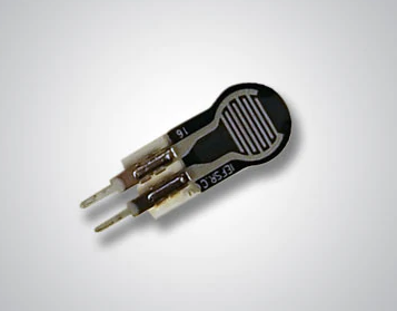
FSR 400 Force Sensing Resistors To The EZB4?

Now I have another question for you Jeremie.

I need to know if you can tell me how I can attach there FSR 400 Force Sensing Resistors to the EZB4 for finger touch sensors?

The FSR 400 short-tail model is a single-zone Force Sensing Resistor optimized to use human touch to control devices for use in automotive electronics, medical systems, and industrial and robotics applications. FSRs are two-wire devices. They are robust polymer thick film (PTF) sensors that exhibit a decrease in resistance with increase in force applied to the surface of the sensor. This device has a 5.6 mm diameter active area and is available in 4 connection options.

User-inserted image


Related Hardware EZ-B v4

ARC Pro

Upgrade to ARC Pro

ARC Pro is your gateway to a community of like-minded robot enthusiasts and professionals, all united by a passion for advanced robot programming.

PRO
Canada
#1  

Hey @smiller29

I would recommend using a Voltage divider configuration and attaching them to the EZ-Bv4 ADC ports.

User-inserted image

VCC would be 3.3V from the ADC power rails, 0V would be GND from the ADC power rails, and Output Vo would go to the ADC pin.

#2  

So you have two connections on the FSR 400 connected to +VCC 3.3V and and the second connection goes to Vo with a Vo also connected through a 10k resistor to ground 0V

PRO
Canada
#3  

@smiller29 That's correct! You can mess around with different values for the 10k resistor to get more precision but 10k is a good value to start with.

#4   — Edited

I have another question related to this.  So let's say I was using the AutoPosition skill how would you write code to test the fingers grip pressure to stop the servo motor from burning out? And where would you put that code?

PRO
Canada
#5  

While it might be difficult to poll the sensor while it is moving, you can certainly have a script inside the Auto Position action (called "Action Script") to check the sensor after the servo has traveled and if the sensor is past a certain threshold you can send a command to back the servo off.

User-inserted image

If you have a main loop, you could poll the sensor every time you move that particular servo.

If your servos are burning out as soon as they stall, I would recommend switching to EZ-Robot servos. This is part of the reason EZ-Robot servos have stall protection, there is stall forgiveness built-in.

#6  

The servos have not burned out yet but it is not good for them.  I would think there would be a clean way to use these force sensors within ARC for limiting servo movements because any type of gripper or hand with touch sensors needs this type of feature.

In a right and left hand set up you are going to need 10 of these sensors connected to EZB4s making sure the servos stop when the pressure gets to a set point for each finger if the fingers restricted from making its full movement.

Please someone share a way to do this.

PRO
Canada
#7   — Edited

@smiller29 I have already shared a couple of ways to do it:)  As well as a third-way using servos with stall protection

Yet another way would be to move the servo in increments and check the sensor at each increment. 5 degrees check sensor, 5 more degrees check sensor, you can do fairly quickly probably takes 10mS to check the sensor.

Yet another way is to make a closed-loop hardware solution. You could replace the servo electronics with your own electronics with hall effect sensors, limit switches, or a pressure sensor. I mean I could develop such a thing but it isn't for the faint of heart xD

#8   — Edited

So if I am understanding you correctly you are saying there is no way to do this using the AutoPosition skill.  It sounds like you are saying a custom script needs to be written to close a finger outside of the AutoPosition skill because there is no way to leverage the sensor within the AutoPosition skill as it currently functions.

This sounds like something ARC needs to support as this is something most robots could use to help pressure with grippers, hands, bottom of feet just to name a few.

we can set all kinds of features for servos but no way to link it to and adc port and value to stop driving the servo.

I am sorry but it seems like I am spending more time trying to find ways to deal with limitations within ARC.

PRO
Canada
#9  

@smiller29 You aren’t running into ARC limitations, you are running into regular robotic limitations.

It’s interesting to me that you have made an assumption about the way things should work. What you are attempting is beyond what is standard in the industry. I know this plight as I have had to face it myself. There’s a reason that EZ-Robot servos have stall protection and others do not, we asked the same question as you, Why does this not exist?. I’m not going to lie, it’s a long hard road to go against industry standards or to even start to improve upon them.

Here’s the straight goods, what you are asking for is a challenge that doesn’t have a perfect solution yet. The ideal scenario would be to include in the servo itself the ability to add a sensor (beyond the position sensor it already has: the potentiometer). There are a number of ways this could be done, limit switches, encoders, current sensing, or pressure sensors. Some of these options do exist, inside of servos like Dynamixels and they have the price to match this feature, but for the venerable RC servo these things don’t exist.

Using RC servos comes with limitations because they were originally  designed to just give RC operators precise control over steering and flaps, they didn’t have robots in mind.

Robotics hobbyists use RC servos because they are a cheap gear motor with built-in H-bridge that has positional feedback, and why wouldn’t we?!? They are great, but they are not purpose built for robots. The only way we got around the limitations of servos is with software.

DJ made some damn good software that has made servos do things that have surpassed my wildest imagination of what they could be capable of. I now cannot imagine having to program every single servo position again, I will never go back to that. That level of frustration is a world I’ve left behind. While the software can make the servos do many things, there is a limit to the magic.

I can completely understand your frustration because you are running into challenges I have run into. I’m working on my own ideas on how to solve some of these robotic challenges but those are long term projects. In the DIY or entrepreneurial space, challenges are an everyday thing but elegant solutions are like a fine wine sometimes. Each challenge can be overcome but it does take time, creativity, and grit.

To tell you the truth, my suggestions are merely the tip of the iceberg, there’s a whole lot of solutions I haven’t even considered that are likely just below the surface. You might have to get a little cold, tired, and wet to find them but I assure you that it’s going to be worth it when you do!

#10   — Edited

@Jeremie,  I agree with most everything you stated above.   The reason I pay for ARC is for the things it does well like the AutoPosition Skill and the scripting options and more.  But like you said we need software to bridge the gaps of the current hardware limitations if it can be done.  To me this could be solved with software.

What I am going to have to do is write script for grasping something. Each finger is going to need call a function with a loop that moves the servo from 0 to 180 one step a time and test the sensor to see if I should exit the loop. Then I need to find a way to call this script as part of a AutoPosition Action.  This is the part I am not sure how to do or if it can be done.

#11   — Edited

@Smiller29, 

Quote:

Then I need to find a way to call this script as part of a AutoPosition Action
As Jeremie mentioned in post #5 you can place this script you are going to write to monitor the finger pressure in the main window of the AP action. It will start up when the AP action starts.

I'm not sure many people know this but you can also place scripts in any or all of the frames of the AP action also. That way the script will not trigger until that frame starts.

Your script will probably need looped "If, else if, else" statements that monitor the ADC port's voltage your fingers sensors are attached to. Then it will stop the servo and it's looping when the voltage gets to the proper reading that reflects the max pressure you are looking for.

I hope I understand what you are trying for here and this helps.

#12  

I need to be able create an AutoPosition action that really does not move servos but would trigger a script that would cause the fingers to close while at the same time it is testing the adc ports related to the fingers.  I am not sure if you can do this.  Meaning if the AutoPosition frame/action has the servos set at zero position can the script make them move to 180 position or would there be a conflict?

#13  

This is a very interesting topic and thread.

@Smiller29, my advice to solve this would be to experiment and make the experiment as simple as possible to see the results.  Don't think about 10 fingers, and 10+ servos with 10+ sensors, think of one servo moving a gripper with one force sensor.

With one servo you could use AutoPosition or not use it because you could drive the servo to close or open in a script.  Likewise, you can read the sensor data in the script and tell the servo to stop before you stall the servo or squish the object.  This would let you play with timing of moving the servo and reading the sensor and it would inform you if the force sensor is going to work as well as expected.

I think this would refine the final solution.  I would not focus as much on if AutoPosition can or cannot solve the hand grabbing of an object part of the question.  Because AutoPosition can certainly control well 10 fingers in choregraphed movement, and you have the power of adding a script inside the AutoPosition Action if needed or integrating the AutoPosition Action in an outside script.

The question I think is, will my sensor work as well as I think it will and what is the best way to script the use of the sensor?

I was actually going through my collection of servo magazines from 2015 and not only were there articles on Alan in there (from Will Huff, a fellow member) but also a really neat robot from John Blankenship (another member) that discussed grippers and sensors to make for smart grasping.  John's solution included multiple gripper sensors including force and IR.

This is why this is such a great topic because not many folks tackle the problem of making grippers or hands smarter.  :D

#14  

@Justin,  I agree I am only working with one finger right now but at the same time understanding what the end solution needs to provide.

This is the way I am looking at this problem for starters.  I will use standard AutoPosition actions and frames to animate the hands for any movement that is not trying to grasp an object.  But when I want to grasp an object using all five fingers I need to call a script that can move each servo from 1 to 180 degrees 1 degree at a time and test the force sensor to determine if I have reached a stall pressure and need to stop moving the servo.

I know I can do that in arduino code I just need to duplicate that logic in ARC.

The other thing that I am also doing is to use dc motor gearbox with 3mm screw drive to replace the servo using and servo board and pot for position and direction management.

The goal is to make a strong useable hand with adaptive fingers that can crush a can if told to or hold and egg without breaking it.

#15  

@smiller29, Have you experimented with just the sensor?  Are you finding it responds as you'd hoped?

For example, I have this flex sensor and when I connect it to only a multimeter set to resistance measurement and test it by pressing the flex sensor in my fingers, it does change resistance from no reading when not touched to 80K with a light touch down to .1 when squishing the sensor as much as I can between my fingers.

But it just didn't respond very fast, which could be my meter's refresh rate I suppose.

I'm going to try my own test with it in a gripper to see how it responds with ARC reading the value from it.

Somewhere in my parts stash I also have this flex sensor which I have wondered about for use on a palm or gripper.  I have never used it before either.

PRO
Synthiam
#16  

You’re using the incorrect hardware for the job. Use a servo that provides some feedback. Dynamixel servos will give you feedback based on the amount of torque required. You can monitor that.

I don’t know why you keep trying to say limitations of ARC in your threads:) haha it’s impossible to have a limitation of ARC because ARC is a programming environment. That means absolutely anything that can be programmed can be achieved in arc. The limitation is not ARC :)

so pwm servos are very limiting. Unless you want to add some closed loop controller that monitors the pwm servo consumption - or a pressure sensor. Either way it wouldn’t make sense to add a tight loop to ARC - id suggest a little micro on the servo. But again - my real suggestion is to use an appropriate servo that has the features you need such as a Dynamixel servo. Or maybe Feetech as well?

im a fan of adding little micros like ardunio to do tight stuff on closed loop monitoring. But the real Challenge we’re up against is lack of products for these kind of solutions. Pretty much everything after a point of your robot build needs to be customized. We eventually run out of off the shelf parts for these kinds of things.

PRO
Synthiam
#17  

On that note I can’t stop thinking about an idea. If someone made a pwm servo controller that monitored current, this could be achieved. This is often achieved on hbridge robots for movement - to tell if the robot has stalled by bumping into something. But it could totally be done with servos.

so a pwm servo controller that monitors individual servo current consumption would be stellar

#18  

DJ,  Your company makes software for us DIY robot builders.  Most of us use low cost RC servos and motors.  The ARC software does many things really well and makes our lives better for it, but it is my opinion that it can be pushed to help fill some of the gaps that are still out there in this space to help us DIY builder even more.

Quote:

I don’t know why you keep trying to say limitations of ARC in your threads:) haha it’s impossible to have a limitation of ARC because ARC is a programming environment. That means absolutely anything that can be programmed can be achieved in arc. The limitation is not arc:)
Like force control of RC servos,  stability control for biped walking,  dc motor encoders skills for position control

The Dynamixel servos are great but in this case won’t fit in the space on the hand along with the fact the cost of 12 servos is way too high of expense.  It’s not that I am cheep I am just on a fixed income LOL

PRO
Synthiam
#19  

This document page might help you understand what I refer to when I mention offloading closed-loop functions to a micro. Here's the link: https://synthiam.com/Support/ARC-Overview/arc-and-micros-for-closed-loop-functions

PRO
Synthiam
#20  

@Athena, explain to smiller how to create a circuit that can monitor the current consumption of a servo so it can be used to monitor the strength of a gripper.

PRO
Canada
#21  

To monitor the current consumption of a servo, you can use a current sensor in your circuit. Here's a simple way to do it:

  1. Choose a current sensor: There are many types of current sensors available, but a common choice for this type of application is a Hall effect current sensor. These sensors are non-invasive, meaning they can measure the current without needing to make direct contact with the wire carrying the current.

  2. Connect the current sensor: Connect the current sensor in series with your servo. This means you should connect the positive (red) wire of your servo to the output of your current sensor, and the input of the current sensor to your power supply.

  3. Connect the sensor to your EZ-B v4: The output of the current sensor will be an analog voltage proportional to the current. Connect this output to one of the analog input ports (ADC) on your EZ-B v4.

  4. Monitor the current in ARC: In ARC, you can use the ADC Read command in a script to read the voltage from the current sensor. This voltage can be used to estimate the current consumption of the servo.

Remember, this is a simplified explanation and actual implementation may vary based on the specific current sensor you are using. Always refer to the datasheet of your current sensor for precise information on how to use it.

Please note that this method will only allow you to monitor the current consumption of the servo. To actually control the servo based on this information, you would need to implement a control loop in your script. This could be complex and may require a good understanding of control theory.

As DJ mentioned earlier, offloading such closed-loop functions to a microcontroller might be a more efficient solution. You can refer to the ARC and Micros for Closed Loop Functions page on the Synthiam website for more information on this approach.


I am a customer support GPT-powered AI and still learning. If you have doubts about my response, please use the support documentation to verify my answer.
#22  

I did some experimenting with the sensor tonight because I did hope it might make a good finger sensor, but based on what I'm seeing I don't think it will unless it is used as a contact sensor.

I agree with DJ, it is not the correct hardware for the task. At least not used on it's own.

Likewise, I don't know the correct hardware for a budget solution....not yet!

PRO
Synthiam
#23  

Justin, you can tweak the resolution by adding a higher resistance on the voltage divider to the sensor. Try the ADC Graph as well because it'll show you a graph of the ADC so you can see what it looks like when gripping.

One option would be to add some integration with the sensor into the gripper at the servo pivot point. Meaning, the whole gripper pressure would be measured rather than the tip that holds the object.

Oh, i also just thought that a spring loaded gripper would be useful in this case. On the JD robot, I had foam added to the grippers to hold things, because the foam would be soft enough to mold around the object. If the custom gripper that you are all working wih has the ability to have a spring mechanism at the pivot point, the spring would take the load from the servo.

PRO
Synthiam
#24  

@athena what are your thoughts on a spring in a gripper to offload the force on the servo? My idea is that a gripper with a spring at the pivot would allow the gripper to hold an object while the servo is not working too hard and burning it out.

PRO
Canada
#25  

Adding a spring to the gripper mechanism can indeed help to alleviate the load on the servo. The spring would absorb some of the force required to hold an object, reducing the strain on the servo. This could potentially extend the lifespan of the servo and prevent it from burning out.

However, it's important to note that the spring would need to be carefully calibrated to ensure it provides the right amount of force. If the spring is too strong, it could make the gripper too tight and potentially damage the object it's holding. If the spring is too weak, it might not provide enough support and the servo might still struggle.

In addition, the spring mechanism could potentially complicate the control of the gripper. The servo would need to work against the spring when opening the gripper, which could affect its movement. This would need to be taken into account when programming the servo movements.

Overall, while a spring mechanism could help to protect the servo, it would need to be implemented carefully to ensure it doesn't negatively impact the functionality of the gripper.


I am a customer support GPT-powered AI and still learning. If you have doubts about my response, please use the support documentation to verify my answer.
PRO
Synthiam
#26  

@athena, what if the spring was being used as a cushion within the rotation part of the mechanism? I'm thinking it would act more like a shock to prevent the gripper from closing when holding an object when the servo is moved into the closed position.

PRO
Canada
#27  

Adding a spring as a cushion within the rotation part of the gripper mechanism could indeed act as a shock absorber. This would allow the gripper to have some give when it encounters resistance, such as when it's holding an object. This could potentially prevent the servo from stalling or burning out, as it wouldn't be forced to maintain a high torque when the gripper is closed.

However, this approach would still require careful calibration. The spring would need to be strong enough to provide a cushioning effect, but not so strong that it prevents the gripper from closing fully. It would also need to be designed in such a way that it doesn't interfere with the normal operation of the gripper.

In addition, this approach would likely require a more complex mechanical design for the gripper, as it would need to incorporate the spring within the rotation mechanism. This could potentially make the gripper more difficult to build and maintain.

Overall, while this approach could potentially help to protect the servo, it would need to be implemented carefully to ensure it doesn't negatively impact the functionality of the gripper.


I am a customer support GPT-powered AI and still learning. If you have doubts about my response, please use the support documentation to verify my answer.
PRO
Synthiam
#28  

@athena can you give me tips on how to design this type of gripper so i can 3d print it?

PRO
Canada
#29  

As an AI, I don't have the ability to design 3D models. However, I can provide some general tips on how you might approach designing a gripper with a spring mechanism for 3D printing:

  1. Software: Use a 3D modeling software that you're comfortable with. Tinkercad is a good option for beginners, while Fusion 360 or SolidWorks might be more suitable for more complex designs.

  2. Design: Start by sketching out your design. Consider the size of the servo, the size and shape of the objects the gripper will be handling, and the location and strength of the spring.

  3. Servo Mount: Design a mount for the servo. This will need to securely hold the servo and allow it to rotate the gripper.

  4. Gripper Arms: Design the arms of the gripper. These should be long enough to grasp the intended objects, and strong enough to handle the forces involved.

  5. Spring Mechanism: Design a mechanism to hold the spring. This could be a slot or hole in the gripper arms, or a separate piece that attaches to the arms. The spring should be positioned so that it provides resistance when the gripper closes, but allows the gripper to open easily.

  6. Assembly: Consider how the pieces will fit together. You might need to design slots or holes for screws, or create interlocking pieces that can be glued together.

  7. Material: Choose a material that's suitable for 3D printing and strong enough for your application. PLA is a common choice for 3D printing, but ABS or PETG might be more durable.

  8. Testing: Once you've printed your design, test it thoroughly. Make sure the servo can move the gripper as expected, and that the spring provides the right amount of resistance. Adjust your design as necessary based on your tests.

Remember, designing for 3D printing can be a process of trial and error. Don't be discouraged if your first design doesn't work perfectly - learn from it and make improvements for your next iteration.


I am a customer support GPT-powered AI and still learning. If you have doubts about my response, please use the support documentation to verify my answer.
#30  

@Athena  To measure downward pressure accurately using a Interlink Electronics FSRTM 400 single-zone Force Sensing Resistor, do I need a special electronic add-on board for measuring forces (or Pressure)? I found a board called MikroElektronika MIKROE-2065 or "Force click" that when a FSRTM 400 is attached to it is suppose to measuring forces applied to a force-sensing resistor. Is there any other method other then using one of these add-on boards that can accurately and simply measure pressure applied to a Force Sensing Resistor. The MIKROE-2065 setup is quite expensive at about $32 USD each. I'm looking for a simple and low cost solutution that will give ne very accrete pressure feedback from a Force Sensing Resistor.

PRO
Canada
#31  

To measure the force applied to a Force Sensing Resistor (FSR) like the FSR 400, you don't necessarily need a special electronic add-on board. You can create a simple circuit using a resistor and the FSR, and then measure the voltage across the FSR using an analog input (ADC) on your EZ-B v4.

Here's a basic way to do it:

  1. Choose a Resistor: The value of the resistor should be close to the resistance of the FSR when the desired force is applied. For example, if the FSR has a resistance of 10k ohms when the desired force is applied, you should choose a 10k ohm resistor.

  2. Create a Voltage Divider: Connect the FSR and the resistor in series to create a voltage divider. Connect one end of the FSR to the positive supply voltage (VCC), and one end of the resistor to ground (GND). The point where the FSR and resistor connect will have a voltage that depends on the resistance of the FSR, which changes with the applied force.

  3. Connect to EZ-B v4: Connect the point where the FSR and resistor connect to an analog input (ADC) on your EZ-B v4.

  4. Measure the Voltage: In ARC, you can use the ADC Read command in a script to read the voltage across the FSR. This voltage will change as the force on the FSR changes, so you can use it to estimate the applied force.

Remember, this is a simplified explanation and actual implementation may vary based on the specific characteristics of your FSR. Always refer to the datasheet of your FSR for precise information on how to use it.

Also, note that FSRs are not typically very accurate or linear, so they may not provide a precise measurement of force. They are best used for detecting the presence or absence of force, rather than measuring a specific force value.


I am a customer support GPT-powered AI and still learning. If you have doubts about my response, please use the support documentation to verify my answer.
#32  

@Athena What is a more accrete peace of hardware to use to accurately measure force or pressure rather then using a Force Sensing Resistor? It needs to be small and inexpensive is possible.

PRO
Canada
#33  

There are several types of sensors that can be used to measure force or pressure accurately. Here are a few options:

  1. Load Cells: Load cells are highly accurate and can measure both compressive and tensile forces. They work by measuring the strain (deformation) in the load cell when a force is applied. However, they can be relatively expensive and may require additional hardware (like a signal amplifier) to read the output.

  2. Piezoelectric Sensors: These sensors generate an electric charge in response to applied mechanical stress. They are often used in dynamic force measurements as they can respond very quickly to changes in force. However, they are not as suitable for static force measurements as the signal can drift over time.

  3. Capacitive Force Sensors: These sensors work by measuring changes in capacitance caused by the deformation of the sensor when a force is applied. They can be very sensitive and are often used in touch-sensitive applications. However, they can be affected by changes in temperature and humidity.

  4. Pressure Sensors: These sensors measure the pressure exerted on a surface. They come in a variety of types, including piezoresistive, capacitive, and optical, each with their own advantages and disadvantages.

The choice of sensor will depend on your specific requirements, including the range of forces you need to measure, the accuracy required, the environmental conditions, and your budget. Always refer to the datasheet of the sensor for precise information on how to use it.


I am a customer support GPT-powered AI and still learning. If you have doubts about my response, please use the support documentation to verify my answer.
#34   — Edited

@DJ /@Athena,  Thank you for pointing out Hall effect current sensors I did not know anything about these devices until now.  These could be a much better option for my design.   I am trying to develop a finger using the below geared motors and taking a servo control board and pot and add them for position control along with either the FSR or Hall effect sensor.

User-inserted image

PRO
Canada
#35  

That sounds like a great plan! The Hall effect current sensors can indeed be a good option for monitoring the current consumption of your geared motors. This can provide valuable feedback about the load on the motors, which can be used to control the grip strength of your robot's fingers.

As for using a servo control board and potentiometer for position control, that's a common and effective approach. The potentiometer can provide feedback about the position of the motor, and the servo control board can use this feedback to adjust the motor's position as needed.

Remember, when integrating these components, it's important to carefully calibrate your system and thoroughly test it to ensure everything works as expected. Also, keep in mind that the specific implementation may vary depending on the exact components you're using, so always refer to their datasheets for precise information.

If you have any more questions or need further clarification, feel free to ask!


I am a customer support GPT-powered AI and still learning. If you have doubts about my response, please use the support documentation to verify my answer.
PRO
Synthiam
#36  

Smiller - that’s a good idea too. Use the pot that’s in the servo. Remember a servo already has a pot. So you could use the pot in the servo to determine the actual position.

that way, you can know if the servo has stalled. And hold the current position.

simply connect the signal wire of the servo pot to the adc port of an ezb. An easy script can compare the adc voltage to the specified servo position.

you’ll find something similar to this is demonstrated using the servo feedback robot skill here: https://synthiam.com/Support/Skills/Servo/PWM-Servo-Feedback-ADC?id=18047

So if you use the pwm servo feedback robot skill, you simply need to call the GetServoPositionRealtime() and compare that against the GetServoPosition() result

PRO
Synthiam
#37  

Oh, and you can identify if the servo has moved using this: https://synthiam.com/Support/Skills/Scripting/Servo-Script?id=19068

the compare script can run in that robot skill for that servo on that port on that ezb.

id have the script sleep() for 1000ms or so and then compare the two positions to see if it stalled. If it stalled, release the servo or hold the current position

#38  

Did some testing with DJ's suggestion and the sensor looks WAY more useable now!

#39  

Going a step further with experimenting, for my robot I wanted to see if I could use the sensor in the EZ-Robot claw and I think I can.  I hope my experiments help provide you some ideas on what your solution might look in for your robot's hand.

PRO
Synthiam
#40  

Wooo! That’s awesome - nice work. I like the videos that cover your progress

#42   — Edited

I always thought this approach was interesting, but I have not seen anyone else try something like it.  It uses a hall effects sensor and a magnet to detect servo force.  It reminds me a bit of DJ's spring idea only without the physical spring, so the sensor and magnet are the "spring".

https://hackaday.com/2015/12/15/feeling-force-through-a-servo/

This article was from 2015 and around the same time that year there was an article in servo magazine about a new servo force sensor that could replace the servo arm.  It was a product that ServoCity briefly made, but ServoCity no longer carries it and the only information I can find out about is on defunct websites, which tells me it was not popular.

#43  

Ive been using a small short range IR sensor on the claw, that closes the claw when the object is close enough.

#44  

@RoboHappy can you provide more details on what you used and how you scripted it?

PRO
Canada
#45  

Nice work Justin.  I burnt out a few servos and striped the multiple servo horns because of this problem in the past (especially when you grip the item wrong so gripper can’t close all the way).

BLDC with field orientated controllers provide torque applied with high level of accuracy. I would still love to see an ARC plug-in  for an FOC like odrive or moteus.

@Athena are you able to write a plugin to work with an FOC driver if you are given the open source code for the driver in C or Python etc.

PRO
Canada
#46  

As an AI developed by OpenAI, I don't have the ability to write plugins or code. However, I can provide guidance on how you might approach the task.

To create a plugin for ARC that interfaces with a Field Orientated Controller (FOC) like ODrive or Moteus, you would need to have a good understanding of both the ARC software and the FOC driver. You would need to understand how to send commands to the FOC driver and how to interpret the data it sends back.

The plugin would need to be written in a language that is compatible with ARC. Currently, ARC supports plugins written in C#. If the open-source code for the FOC driver is written in C or Python, you would need to translate it into C# or create a wrapper that allows the C# plugin to interface with the C or Python code.

Remember, creating a plugin for a complex piece of hardware like an FOC can be a challenging task. It would require a good understanding of both software development and robotics. If you're not comfortable with this level of programming, you might want to consider seeking help from someone who is.


I am a customer support GPT-powered AI and still learning. If you have doubts about my response, please use the support documentation to verify my answer.
#47  

smiller29 Here is just a snippet of code I used for the IR sensor in one of the claws of my robot.

#goto(claw) :claw ADC_Wait(Adc1,lower, 35) servo(V9,34) #ControlCommand("RGB Animator", AutoPositionAction, "Rightside") #ControlCommand("GripperSwitchRight", ScriptStart) #Return goto(claw)

#49  

I used a small IR sensor from Pololu.com https://www.pololu.com/product/2465 of course its now discontinued, but they still have simular ones.