
robohobo
Dagu 4Ch Motor Controller(Rover 5) Assistance Needed!
hello all, im in the process of building my first ez robot and ive realized how much i truly have to learn at once. anyway when i ordered my rover 5 chassis (4 motor w/ encoders model) i opted to go with the dagu 4ch motor driver since it supported the encoders. i now realize that as a beginner wanting to jump in head first this wasnt the best idea. im fairly certain ive figured out how to correctly connect the driver to ez-b and both to my 6v sla power source, but if anyone has a diagram of how to do this properly i would feel more comfortable. my major problem is scripting a custom control panel to drive this thing. i have no clue what im doing and a push in the right direction would be greatly appreciated.
maybe DJ will add this motor controller in a future update? as i understand it ez-robot works very closely with dagu and carrys the rover 5 in store so it seems likely. ill cross my fingers.

So im not sure exactly what happend but I got everything all hooked up and when I plugged power into the ez-b all the motors started moving in different directions. I really can't afford to fry the Ez-b any thoughts?
How did you have it hooked up?
All signal wires should be ground when the EZB is disconnected from the PC and when PWM is off and Digital is off.
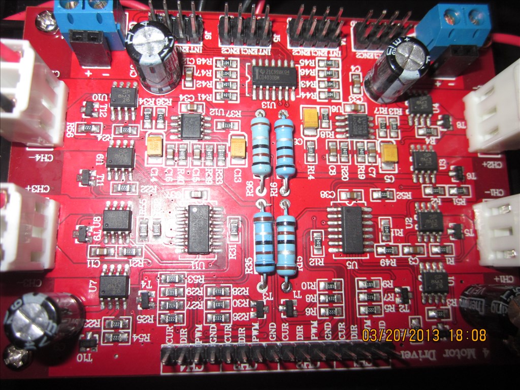
If you can list out which port you have connected where and which colour wire (or sig, vcc & ground if that's easier)
From what I understand of the manual you want...
D0 Sig to CH1 DIR D0 Gnd to CH1 GND D0 VCC not connected D1 Sig to CH1 PWM D1 Gnd to CH1 GND D1 VCC not connected D2 Sig to CH2 DIR D2 Gnd to CH2 GND D2 VCC not connected D3 SIG to CH2 PWM D3 Gnd to CH2 GND D3 VCC not connected D4 SIG to CH3 DIR D4 Gnd to CH3 GND D4 VCC not connected D5 Sig to CH3 PWM D5 Gnd to CH3 GND D5 VCC not connected D6 Sig to CH4 DIR D6 Gnd to CH4 GND D6 VCC not connected D7 Sig to CH4 PWM D7 Gnd to CH4 GND D7 VCC not connected
Optional ADC0 Sig to CH1 CUR ADC0 Gnd to CH1 GND ADC0 VCC not connected ADC1 Sig to CH2 CUR ADC1 Gnd to CH2 GND ADC1 VCC not connected ADC2 Sig to CH3 CUR ADC2 Gnd to CH3 Gnd ADC2 VCC not connected ADC3 Sig to CH4 CUR ADC3 Gnd to CH4 GND ADC3 VCC not connected
D0 is direction of CH1 D1 is PWM/Speed for CH1 D2 is direction of CH2 D3 is PWM/Speed for CH2 D4 is direction of CH3 D5 is PWM/Speed for CH3 D6 is direction of CH4 D7 is PWM/Speed of CH4 ADC0 is current monitor CH1 ADC1 is current monitor CH2 ADC2 is current monitor CH3 ADC3 is current monitor CH4
At least that's how I interpret the manual
@Rich first off thanks again for taking the time to help me out. So I disconnected everything and connected it as you mapped out. I wasnt sure exactly how to test if this was correct so i sent it PWM(D1,90) Set(d0,ON) and one wheel began to spin, i then tried a few more scripts while it was still spinning (ie PWM(D1,0) and Set(D0,OFF) and a few other values in the pwm) and it just kept on spinning. Im sure im just missing something as these little tests were my first attempts at script. I gather this is your area of expertise. my robots almost rolling! so close I can taste it.
Easiest way to test would be to add 4 Set Digital controls and 4 PWM controls.
The 4 Set Digitals for direction, mapped to D0, D2, D4 & D6 The 4 PWM controls for speed, mapped to D1, D3, D5 & D7
Then click and slide in ARC to see what happens.
i.e. Set the PWM for one wheel to maximum (100) and see what happens, then click on the set digital for the same wheel and see if it reverses. Slide the PWM down towards 0 to see if it slows down. Click stop on the PWM to see if it stops.
Try with this project (updated 2013.03.28)
I set up the controls based on the above ports. This is how I interpret the manual, it may not be right but looking logically it should.
I also took the liberty of setting up the Custom Movement Panel for forwards and reverse. I will leave you to attempt left and right (however ask if you get stuck). This is provided the above is correct of course.
@robohobo I'm glad rich found labels for the connections. , I been moving the past week sorry I wasn't able to get to you quicker but rich is pretty good with this stuff too - Josh
Awesome. This should be all I need to be on my way =). I didn't even think to use sliders since I'm not at all familiar with ARC yet, but now that my first bot should be rolling im sure I'll be able to pick it up as I go. Thanks for helping me get off on the right foot @Rich. @jstarne1 things come up man, I appreciate you trying. I'm to excited, I'm gonna go work on my bot now!
Alright sooooooo I messed with the project you made for me (very nice) and i tried the PWM sliders first, all seemed well. then i tried to change the direction of the wheels and nothing happened. i moved on to the custom Movement Panel and full forward turns the wheels on each side in different directions( something i could probably do by myself if the direction contol was working) the stop functions do not work on the sliders or the Movement Panel but adjusting the sliders individually to 0 turned them off. the reverse on the Movement Panel turns all motors in the same direction as forward. Is there a chance that the motor direction is controled in a different way? Or could I have wired up the power improperly?