Asked — Edited

Dagu 4Ch Motor Controller(Rover 5) Assistance Needed!

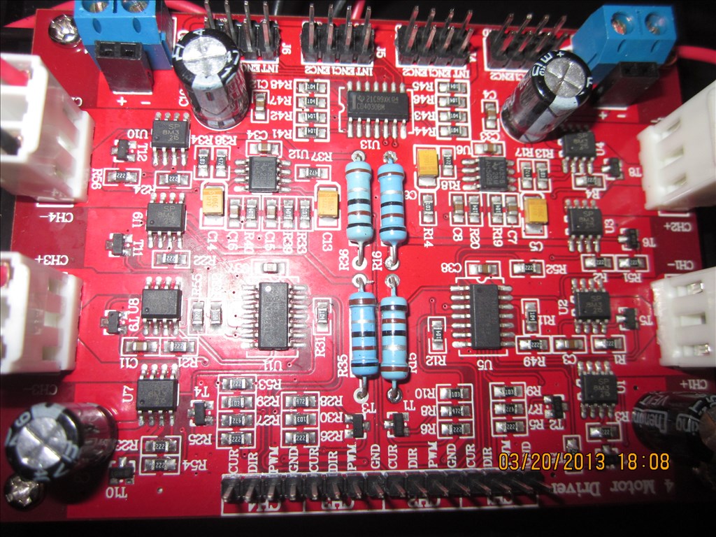
hello all, im in the process of building my first ez robot and ive realized how much i truly have to learn at once. anyway when i ordered my rover 5 chassis (4 motor w/ encoders model) i opted to go with the dagu 4ch motor driver since it supported the encoders. i now realize that as a beginner wanting to jump in head first this wasnt the best idea. im fairly certain ive figured out how to correctly connect the driver to ez-b and both to my 6v sla power source, but if anyone has a diagram of how to do this properly i would feel more comfortable. my major problem is scripting a custom control panel to drive this thing. i have no clue what im doing and a push in the right direction would be greatly appreciated.

maybe DJ will add this motor controller in a future update? as i understand it ez-robot works very closely with dagu and carrys the rover 5 in store so it seems likely. ill cross my fingers.


ARC Pro

Upgrade to ARC Pro

Unleash your creativity with the power of easy robot programming using Synthiam ARC Pro

#3  

this is my obstacle. can anyone help? ive posted my problem in a few related threads and i almost got help once.

United Kingdom
#4  

Just taking a look at the manual for it...

The Current outputs (cur) can be connected to the ADC ports of the EZB to monitor the current. 1V = 1A with a maximum of 5V so they are fine to just connect direct to the EZ-B. Use ADC controls to monitor it or a script with GetADC() to check the port and act on a high current.

Direction pin is either a high or low for direction. So I assume connect to a dgital port and a Set Digital control or a Set() script command, on for forwards and off for reverse (or vice versa, it didn't say which yet).

PWM to a digital port and use PWM sliders or PWM() command to set the speed.

I haven't a clue when it comes to the encoders.

Of course, there may be an easier way of doing it, I'm just going from what I read in the manual.

#5  

@Rich THANK YOU! ive been trying to get a little help on this for days. the translation of what the stuff in the manual means to me and the ez-b is where i was a bit lost. thanks for bridging the gap. im still not too clear on scripting the Movement Panel but i bet i can figure it out now that im about 75% less lost.

PRO
Synthiam
#6  

Sorry, I haven't seen that controller before. If I have time this week I may be able to review the manual for you. Encoders are quite useless in the real world. They sound fabulous in theory, but the they're not used anymore in robotics. To truly understand where your robot is, stay tuned for a future ARC update.

I have been working on something truly awesome! :)

#7  

@DJ Sures are you ever not working on something truly awesome? I had already abandoned the encoders because I'm simply not experienced enough, so this is great news. You and @Rich have made my day and resparked my building bug. Project post soon! Thanks Again!

United Kingdom
#8  

Once you have it all set up and checked that what I believe is right actually is right I'll give you a nudge in the right direction with the scripting of the movement control.

But, to put it basically you just need to consider how it will move.

Forwards - SetDigital to either high or low (on or off) depending on which does which for all 4 motors. PWM to 100 for full speed. Reverse - As above but SetDigital the other way. Left - Left hand wheels to go in reverse at full speed, right hand wheels forwards at full speed. Right - Left hand wheels forwards at full speed, right hand wheels in reverse at full speed.

You could turn left and right with a forwards ARC by just slowing the left or right wheels down. If the wheels on the left are slower than the ones on the right (and slower includes running the other way) the robot will turn in the direction of the slower wheels.

#9  

So im not sure exactly what happend but I got everything all hooked up and when I plugged power into the ez-b all the motors started moving in different directions. I really can't afford to fry the Ez-b any thoughts?

United Kingdom
#10  

How did you have it hooked up?

All signal wires should be ground when the EZB is disconnected from the PC and when PWM is off and Digital is off.

If you can list out which port you have connected where and which colour wire (or sig, vcc & ground if that's easier)

From what I understand of the manual you want...

D0 Sig to CH1 DIR D0 Gnd to CH1 GND D0 VCC not connected D1 Sig to CH1 PWM D1 Gnd to CH1 GND D1 VCC not connected D2 Sig to CH2 DIR D2 Gnd to CH2 GND D2 VCC not connected D3 SIG to CH2 PWM D3 Gnd to CH2 GND D3 VCC not connected D4 SIG to CH3 DIR D4 Gnd to CH3 GND D4 VCC not connected D5 Sig to CH3 PWM D5 Gnd to CH3 GND D5 VCC not connected D6 Sig to CH4 DIR D6 Gnd to CH4 GND D6 VCC not connected D7 Sig to CH4 PWM D7 Gnd to CH4 GND D7 VCC not connected

Optional ADC0 Sig to CH1 CUR ADC0 Gnd to CH1 GND ADC0 VCC not connected ADC1 Sig to CH2 CUR ADC1 Gnd to CH2 GND ADC1 VCC not connected ADC2 Sig to CH3 CUR ADC2 Gnd to CH3 Gnd ADC2 VCC not connected ADC3 Sig to CH4 CUR ADC3 Gnd to CH4 GND ADC3 VCC not connected

D0 is direction of CH1 D1 is PWM/Speed for CH1 D2 is direction of CH2 D3 is PWM/Speed for CH2 D4 is direction of CH3 D5 is PWM/Speed for CH3 D6 is direction of CH4 D7 is PWM/Speed of CH4 ADC0 is current monitor CH1 ADC1 is current monitor CH2 ADC2 is current monitor CH3 ADC3 is current monitor CH4

At least that's how I interpret the manual

#11  

@Rich first off thanks again for taking the time to help me out. So I disconnected everything and connected it as you mapped out. I wasnt sure exactly how to test if this was correct so i sent it PWM(D1,90) Set(d0,ON) and one wheel began to spin, i then tried a few more scripts while it was still spinning (ie PWM(D1,0) and Set(D0,OFF) and a few other values in the pwm) and it just kept on spinning. Im sure im just missing something as these little tests were my first attempts at script. I gather this is your area of expertise. my robots almost rolling! so close I can taste it.

United Kingdom
#12  

Easiest way to test would be to add 4 Set Digital controls and 4 PWM controls.

The 4 Set Digitals for direction, mapped to D0, D2, D4 & D6 The 4 PWM controls for speed, mapped to D1, D3, D5 & D7

Then click and slide in ARC to see what happens.

i.e. Set the PWM for one wheel to maximum (100) and see what happens, then click on the set digital for the same wheel and see if it reverses. Slide the PWM down towards 0 to see if it slows down. Click stop on the PWM to see if it stops.

United Kingdom
#13  

Try with this project (updated 2013.03.28)

I set up the controls based on the above ports. This is how I interpret the manual, it may not be right but looking logically it should.

I also took the liberty of setting up the Custom Movement Panel for forwards and reverse. I will leave you to attempt left and right (however ask if you get stuck). This is provided the above is correct of course.

#14  

@robohobo I'm glad rich found labels for the connections. , I been moving the past week sorry I wasn't able to get to you quicker but rich is pretty good with this stuff too;) - Josh

#15  

Awesome. This should be all I need to be on my way =). I didn't even think to use sliders since I'm not at all familiar with ARC yet, but now that my first bot should be rolling im sure I'll be able to pick it up as I go. Thanks for helping me get off on the right foot @Rich. @jstarne1 things come up man, I appreciate you trying. I'm to excited, I'm gonna go work on my bot now!

#16  

Alright sooooooo I messed with the project you made for me (very nice) and i tried the PWM sliders first, all seemed well. then i tried to change the direction of the wheels and nothing happened. i moved on to the custom Movement Panel and full forward turns the wheels on each side in different directions( something i could probably do by myself if the direction contol was working) the stop functions do not work on the sliders or the Movement Panel but adjusting the sliders individually to 0 turned them off. the reverse on the Movement Panel turns all motors in the same direction as forward. Is there a chance that the motor direction is controled in a different way? Or could I have wired up the power improperly?

United Kingdom
#17  

It sounds like direction is controlled a different way, I'll have to revisit the manual and look in to it.

Once direction control is known the custom Movement Panel can be altered for all wheels to move in the same direction. Depending on mounting positions of the motors will have an effect on which need to be moving forwards and which reverse, I just assumed all were the same way around.

When I get chance I'll have another look at the manual.

United Kingdom
#18  

I'll throw this up for anyone else to have a look over too while I try to find time to look again. The manual can be downloaded here

And an extract;

Quote:

Control logic: The built in control logic allows each motor to be controlled by 2 pins. Driving the direction pin high or low will cause the motor to run forward or reverse. The PWM pin is used to control the motor speed. When this pin is low, the motor is off. When this pin is high the motor is at full power. To vary the speed of the motor this pin must be Pulse Width Modulated

To me that says PWM to the PWM pins for speed control and off, and high/low (digital on/off) for direction control.

User-inserted image

Ignore current for now (however I'm 99.9% sure a signal from an ADC connects to read the Current value from 0 to 5). And ignore the encoders.

I can't see that it's anything but what I've assumed and set up in the project file unless Set Digital doesn't work how I expect it to.

One other test could be to PWM 0 and PWM 100 to the direction pin to see if direction changes. However I was under the impression Digital on is the same as PWM100 and Digital off is the same as PWM0.

I've added a script to the project file called "Try Me". It uses PWM on all pins. It should, if it needs PWM rather than Set Digital, spin forwards for 5 seconds, stop for 5 seconds, spin in reverse for 5 seconds then a little bonus. Let me know how it works out. I refuse to be beaten :)

#19  

In the power connections I read that the motor power connections must not be connected without fort connecting the +5v to logic, I have the +5v coming from ez-b which I'm plugging in last. Could this be my issue? Do I need a switch or something for motor power supply?

United Kingdom
#20  

That shouldn't matter as far as I can tell but it could be worth disconnecting the motor power supply. Then power up the EZB - as when you first power on the board the +5v (VCC) from the EZ-B will be +5v but all signal wires will be low, or ground. So when you power the whole lot on the +5V is the first to be receiving power anyway. Then connect the battery power supply. It seems like a lot of work and I don't really see why it would make a difference but at this stage everything is worth trying.

Have you tried the updated project file yet and run the "Try Me" script? You'll have to download it again from the cloud (or via ARC open from cloud) for the updated script (and bonus extras since I was bored at work). I've written it so it uses PWM for everything to see if that works.

#21  

Rich, your awesome. I'll try everything tonight when I get home.

United Kingdom
#22  

If you try the project first before messing with the power side of things, if it works then no need to muck about (if you did it the other way around, i.e. disconnect power first then run the project we wouldn't be sure what fixed it - if it works).

I'll be sure to check the forums in the morning when I get up (or afternoon, it's been a while since I had the chance for a lie in), time difference means it's 1:20am here! I wont let this one beat me:) the manual and sales pitch says it's simple, I'd hate to see complicated!

I can't remember if I changed the movement panel, but the script will run through forward, reverse etc. once we figure out what needs to be done then we can tackle the Movement Panel :).

#23  

I tried it all. I first left the power situation alone and tried the new project (still just goes in a single direction with the only way to stop motors being pwm sliders) I then tried powering up the EZ-B first (which provides the +5v to the motor controller), and then connecting the power for the motors. still the same issues I even tried powering up and connecting ez-b before connecting motor power. no change.

theres even a flux capacitor and it still doesnt work ;)

its like we have plutonium, a nulear reactor, a flux capacitor, and a delorian, and we cant figure out how to steer it. :D

#24  

i rl=http://www.mcs.uvawise.edu/wiki/index.php/Rover_5_(Battered_Spirit)]i

I found this, it's arduino but it had the code and wiring and I thought it might help somehow

United Kingdom
#25  

Did the speed control work? (i.e. the bit at the end of the code "when this baby hits 88mph..." part)? Or did it just go full speed for the 10 seconds at the end?

I just found the board for pretty cheap, I'm tempted to grab one because I can't see what's wrong. Checking the Armadillo code for it shows pretty much the same as what I first thought (PWM for speed, Set on or off for direction).

Are you 100% sure the signal connections from the EZB to the board are right?

Makes no difference if I order it today, tomorrow, Sunday or Monday due to Easter but if we have hit a wall I'll get one on order (I need something for a rover project anyway, this is as good as anything else I guess)

#26  

I'm not sure what to do, but I'd hate to have you base your purchase off of me needing help. I'm starting to think I should have just went with 2 l298s.

United Kingdom
#27  

I need to get a H-Bridge for my next project which is to be 4wd so it's a good choice anyway. And since the next one will probably have a lot on show and exposed it needs to look good too. Plus it's cheaper than 2 of the other H-Bridges I was considering (but currently have issues with in my hearoid). So not totally basing it off you needing help (although the fact I've not beaten it yet is part of it).

#28  

Well in that case I'm glad to have someone so steadfast on the task. Id really rather not admit defeat either and buying another motor driver or 2 would postpone me getting other parts. As far as aesthetics goes, with some clean wireing it does look awesome, just wish I knew what it wanted from me lol

#29  

still havent got this figured out.

i was wondering if its possible that it wont funtion properly without the cur pin connected. i had them connected but i took them off since @rich indicated them as optional and i ran out of jumpers just short of having jumpers for the grounds on the CUR channels.

what else could it possibly be? a faulty controller? not enough power? (everything connected to single 6v. 4.5ah SLA battery)

any thoughts are appreciated.

United Kingdom
#30  

I haven't forgotten this I just never got around to ordering the controller for one reason or another.

The CUR connections go to ADC ports so it shouldn't make a difference.

I've looked over the manual too many times now, it should be simple. PWM is easy (did the speed control at the end of the script I wrote give speed control? It should have slowly ramped up to top speed) Ground is easy DIR says it's either on or off for forwards or reverse. A set digital gives that on or off.

All I can think of trying now is to confirm the set digital does what I assume it does...

You could try pulling the jumper from DIR while it's spinning forwards to see if that changes direction. No signal is a digital low, which according to the manual sends it the other direction.

You could also, at your own risk - I do not suggest this, I shouldn't even post it but I will because we are hitting a wall... You could remove the jumper from the DIR pin and connect DIR to ground to see if that spins it the other way.

#31  

I have this setup working. I wired all four PWM channel inputs to a single PWM output on the EZ B board. Think of it as the gas pedal of a tank. Remember you need a ground wire to go with the PWM output.

Then wired two on the DIR pins together (i.e. CH 1 and 2 DIR inputs.) These are left side motors for me. I ran a ground for each of these as well.

Same thing with the other two DIR pins. (.i.e. CH 3 and 4 DIR inputs.) These are right side motors for me. I ran a ground for each of these as well.

Now you have your left and right levers controls of the tank.

A custom Movement Panel used to work nicely with this setup. There appears to be a bug in the latest code that prohibits the speed control of the custom Movement Panel from working correctly for me.

I initially controlled it with a Vertical servo (gas pedal) and two digital output controls (left and right tank levers). Push both levers forward (i.e. digital outputs on) and step on the gas (i.e. set the PWM to anything but 0). Away she goes.

To turn one lever forward (i.e. Digital output on) and the other lever backward (i.e. other Digital port off). To stop set PWM to 0 digital outputs won't matter. Easy to test operation. Enjoy.

I ignored the current outputs so far and I do not believe EZ B supports the encoders yet. I am hoping that will happen in a future release.

#32  

Is there any reason that it would work with the dir and Pwm tied together but not seperated? Controls sound like exactly what we tried except tied together as well. I hate giving up, but Im finding that I hate looking at my unborn robot more. My next step is to diagram my entire wireing scheme to confirm its all good and if it is, then I'm getting 2 l298s because I'm out of ideas. The money was supposed to go to servos but I'd rather be missing an arm than my legs and I bet my bot feels the same.

United Kingdom
#33  

I can't see why, especially as the script in the project I set up sets the same on or off and PWM as required. I can only suggest attempting it since it seems to work for @RobertL184

If you can diagram it as a schematic just to ensure everything is as thought that would be great. www.CircuitLab.com is simple to use and free if you don't have any other software or aren't familier with any other. Or ExpressPCB is a free schematic application.

I'm eager to get this set up and working for you. It'll ultimately decide if I go for this controller or the L298 (since this one is out of stock where I was going to get it hence not having it yet).

#34  

I hooked up +5V input power on the dagu controller board to the ez-b +5V external power and run power to the ez-b and Dagu controller motor power from the ez-b battery pack. I added a switch to the plus side of the battery pack. The whole thing comes up at once just fine. When I first set it up I used Standard AA batteries. I have since switched to NiMH batteries. Mine has a slight pull to the right over longer distances on a straight course, but this isn't unusual. I'm hoping when ez-b eventually supports encoders to be able to compensate. My brother has the same setup running as well.

United Kingdom
#35  

Haven't got any input on this yet, but I have a Dagu R5 (4x4) and a Dagu 4channel motor controller arriving next week. I'll try setting it up as per Rich's suggestion, then we can rule out the setup as the problem. (I.E, hardware error or user error)

United Kingdom
#36  

That'll be great Bill. I've put a project in one of the posts in this topic too to save you having to set all that up.

United Kingdom
#37  

Super, will get it downloaded. Expecting the dagu and controller to arrive on Tuesday or Wednesday. :)

United Kingdom
#38  

Where did you get it Bill? I was after one but it was out of stock when I looked so hung fire on it.

#39  

So big news! My original wireing was done with a jumper wire starter pack, and being short on proper sizes I had pieced quiet a few together with different lengths. Today I bought proper lenght jumpers and decided I'd first try rewiring from @Rich s original layout in case the franken-jumpers were to blame. I ran the test project again and to my amazement it worked! Well mostly, the motors now do change directions and the back to the future script did vary the speed ( Pwm sliders also work) but none of the commands stop the motors. The only way I can stop them is to drag the pwm to a very low number, wait a sec, then drag to 0. I don't know still of it was the jumper mess or me messing up but it's much cleaner now and it works! Now how do I stop it?

#40  

My Stop Script reads:

PWM(D14,1) sleep(75) PWM(D14,0) set(d14,off)

D14 is the PWM output on my EZ-B that drives the Motor Speed on the DAGU controller.

I have a FWD Script, LEFT Script, Right Script, BACK Script, and a STOP Script.

United Kingdom
#41  

@Rich : Purchased mine from RoboSavvy. You can buy from their website or their Ebay store.

The website prices are lower, but I think the shipping is higher. I guess it probably balances out.

United Kingdom
#42  

@Bill Thanks.

@RoboHobo great news :)

To stop, it looks like you will need to use @RobertL184's script.

#43  

Thank you all very much. @Rich especially for taking so much time to help me. Project post within the week I'd say. =)

United Kingdom
#44  

You're more than welcome. Looking forward to see the project :)

United Kingdom
#45  

Okay! So my dagu+board turned up today, and after work I set about getting it all wired together. I followed Rich's example from the first forum page, then figured out how to wire the power on and what went where.

So, did it work? Well, yes. Ish.

Problem 1, the plugs on the Dagu chassis' motors are backwards. They are one-way only plugs, so connect only one way to the board. But when plugged in thusly, the red wire is on the gnd pin, not the red one. Without un-crimping/re-crimping the plugs, they will always be backwards. Thankfully, as I udnerstand, that doesn't matter really. It just means everything backwards.

Anywho, problem 2...

With all 4 motors hooked up, the pairs need their directions reversed relative to each other, otherwise the script fails.

If we say for arguments sake, the motors are labelled thusly; ^Front^ 1-----3 | | | | | | 2-----4

(Warning, weird pseudo-code coming up!)

In this case, motor 1 has to be set Dir(0) with motor 2 Dir(1), otherwise they both turn opposite directions, resulting in a whole lot of unhappy motor-fairies. Could this be a result of the weird plugs, I don't know. The same goes for 3 and 4. As a result, the custom Movement Panel doesn't work (It sets all to off or on). Obviously, this fix is quick and simple.

Problem 3... For some reason, when using the Stop button on the custom movement panel, none of the motors stop turning. In addition, if you slide quickly from ON to OFF on a PWM slider, the motor doesn't stop. Only when going gradually from top to bottom does it shut off. It's almost like it needs to hit 1% then 0% to turn it off. I don't know if this is a Dagu issue or an EZB issue.

Anywho, I'm exhausted from work, so I'm going to fiddle again tomorrow.

Hope some of this makes sense! :D

  • Bill.
United Kingdom
#46  

^^^Addition...

I so should've read the rest of the forum post before putting up my post. I see from Robert's script that he already addressed the stopping issue.

Makes me wonder, why is this the case? Is it dagu or ezb based, and would kicking it help? ;)

United Kingdom
#47  

I'm wondering, (It's early, forgive me!).. Can everything share a common ground? Could I, for example, take D0 gnd to a breadboard, and put all the grounds on to that? With the way Robert has it, one channel for PWM (Makes sense, you want them all going the same speed in the end), then the channels paired off (1,3 / 2,4) for dir, and then a common ground, it'll require only three EzB outputs to be used?

United Kingdom
#48  

..So I thought before re-wiring, I would try editing Rich's script, to try and get the directions right etc. I hooked up the logic power, then connected the motor power and had an unexpected encounter with Puff the Magic Smoke. :/ Thankfully from the Dagu board, not the EzB. No idea why, though. Checked, double-checked, triple-checked the wiring, everything okay.

Unhooked everything, plugged in Logic power, then motor power and a second coming of Puff, some more magic smoke. :/

Bummer.

  • Bill.
#49  

so awesome! drove it around my livingroom for too long (if you test it 3 times, your playing with it).

one question though, when i was putting things back together more permanatly i forgot to plug the +5v and gnd from the ez-b to power the logic. It was unplugged the entire time i was scripting the rest of the custom Movement Panel and through all the "testing" i did once i had it right. what exactly is this powering?

United Kingdom
#50  

That's concerning Bill, can you send it back under warranty?

Great news Robohobo. I have no idea what it powers though. It may be +5V to supply the microcontroller as I have recently learnt some other controllers have... but I'm guessing.

United Kingdom
#51  

It's difficult; I can't, in good conscience, completely rule out user error. I should really know better than to fiddle with complex things when it's stupid-o-clock and I've just got up.

Thankfully, the dagu boards aren't expensive, so another one is already on it's way. With a nothing-before-10am ban on it lol

Any idea on the common ground thing btw?

#52  

I grounded everything as @Rich originally suggested (the ports that control pwm and dir are grounded to Gnd of the corresponding channel on the dagu board) and it works great! Why exactly is it done this way? can anyone steer me to where i can learn more about proper grounding?