
ESP32 Cam EZB Firmware
Transform ESP32-CAM into an EZ-B for Synthiam ARC: simultaneous video streaming and servo control in a compact, cost-effective solution.
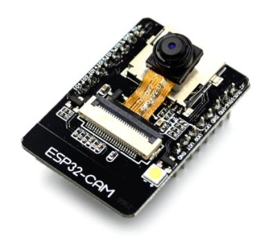
Compatible Hardware
Description
This firmware transforms an ESP32-based camera module into a full EZ-B-compatible controller with integrated Synthiam ARC video streaming. It enables the ESP32 to function simultaneously as a real-time camera and as a robotics/IoT peripheral controller - all in one compact board.
Summary
This firmware turns an ESP32 camera module into an ARC-compatible EZ-B controller with live video, digital I/O, ultrasonic measurement, and optional ADC support.
To deploy successfully you must:
- Select the correct CAMERA_MODEL_* define.
- Edit the mapping tables to match your ESP32 board’s GPIO.
- Flash the firmware and connect through Synthiam ARC.
Once mapped, the ESP32 behaves like a compact, Wi-Fi enabled, vision-equipped EZ-B controller ready for robotics and IoT applications.
Important note about PWM/actuators: If PWM output for actuators is required, use an external controller such as a PCA9685, SSC-32, or another dedicated PWM/servo driver. This is necessary due to the limited processing and I/O capability of ESP32 devices-especially camera-based modules. The camera subsystem consumes a significant amount of CPU time, DMA bandwidth, GPIOs, and LEDC timer resources, so PWM generation must be offloaded to a slave peripheral controller for reliable operation.
What the Firmware Provides
EZ-B Compatibility The ESP32 accepts ARC control commands and behaves like an EZ-B, allowing digital outputs, ultrasonic sensors, and other peripherals to be controlled directly from Synthiam ARC.
Integrated Camera Streaming The onboard OV2640 camera streams JPEG video to ARC, providing live visual feedback alongside peripheral control.
Simultaneous Operation Camera streaming and peripheral control run together, making the ESP32 ideal for robotics scenarios where vision and control must happen at the same time.
Supported ESP32 Camera Boards
This firmware includes camera model definitions for many common modules, including variants of classic AI-Thinker style boards, M5Stack units, and ESP32-S2/S3 models with cameras.
Supported models include:
- CAMERA_MODEL_AI_THINKER
- CAMERA_MODEL_WROVER_KIT
- CAMERA_MODEL_ESP_EYE
- CAMERA_MODEL_M5STACK_PSRAM
- CAMERA_MODEL_M5STACK_V2_PSRAM
- CAMERA_MODEL_M5STACK_WIDE
- CAMERA_MODEL_M5STACK_ESP32CAM
- CAMERA_MODEL_M5STACK_UNITCAM
- CAMERA_MODEL_M5STACK_CAMS3_UNIT
- CAMERA_MODEL_TTGO_T_JOURNAL
- CAMERA_MODEL_XIAO_ESP32S3
- CAMERA_MODEL_ESP32_CAM_BOARD
- CAMERA_MODEL_ESP32S3_CAM_LCD
- CAMERA_MODEL_ESP32S2_CAM_BOARD
- CAMERA_MODEL_ESP32S3_EYE
- CAMERA_MODEL_DFRobot_FireBeetle2_ESP32S3
- CAMERA_MODEL_DFRobot_Romeo_ESP32S3
Only one camera model should be enabled in the firmware at a time. A mismatched model typically results in "frame size = 0" or initialization errors.
Understanding GPIO Mapping (Very Important)
Different ESP32 camera boards have:
- different exposed header pins
- different analog capabilities
- different LEDC PWM support
- pins occupied by the camera bus (XCLK, PCLK, VSYNC, HREF, SDA/SCL, etc.)
- differences between ESP32, ESP32-S2, ESP32-S3 variants
Because of this, ARC’s digital and ADC port numbers do NOT directly match ESP32 pin numbers. To solve that, the firmware uses mapping tables that translate between:
ARC Dx   -> ESP32 GPIO
ARC ADCx -> ESP32 ADC-capable GPIO
This mapping layer exists so that:
ARC always sees consistent "Dx" ports (0-23) regardless of hardware Camera-critical pins are never accidentally used for peripherals Different ESP32 board layouts remain compatible by changing only one mapping section PWM-capable pins are used only where supported Project code in ARC remains portable across ESP32 models
Editing the Mapping for Your ESP32 Module
You must customize the mapping arrays to reflect the physical pins on the ESP32 camera board you are using. This is the only hardware-specific part of the firmware.
This is how ARC ports and ESP32 parts are mapped. In the example below, ARC D0 is mapped to ESP32 port #2. Example of the concept for WRover with camera:
const uint8_t ARC_TO_ESP_DIGITAL_PIN_MAPPING[24] = {

  2,   // ARC port D0
  13,  // ARC port D1
  14,  // ARC port D2
  15,  // ARC port D3
  12,  // ARC port D4
  0xff, // ARC port D5 (not used)
  0xff, // ARC port D6 (not used)
  0xff, // ARC port D7 (not used)
  0xff, // ARC port D8 (not used)
  0xff, // ARC port D9 (not used)
  0xff, // ARC port D10 (not used)
  0xff, // ARC port D11 (not used)
  0xff, // ARC port D12 (not used)
  0xff, // ARC port D13 (not used)
  0xff, // ARC port D14 (not used)
  0xff, // ARC port D15 (not used)
  0xff, // ARC port D16 (not used)
  0xff, // ARC port D17 (not used)
  0xff, // ARC port D18 (not used)
  0xff, // ARC port D19 (not used)
  0xff, // ARC port D20 (not used)
  0xff, // ARC port D21 (not used)
  0xff, // ARC port D22 (not used)
  0xff  // ARC port D23 (not used)
};

const uint8_t ARC_TO_ESP_ADC_PIN_MAPPING[8] = {

  0xff, // ARC port ADC0 (not mapped)
  0xff, // ARC port ADC1 (not mapped)
  0xff, // ARC port ADC2 (not mapped)
  0xff, // ARC port ADC3 (not mapped)
  0xff, // ARC port ADC4 (not mapped)
  0xff, // ARC port ADC5 (not mapped)
  0xff, // ARC port ADC6 (not mapped)
  0xff  // ARC port ADC7 (not mapped)
};

// ----------------------------------------------------------------
// Serial Expansion UART Configuration (in ARC this is UART #0)
// ----------------------------------------------------------------
#define SERIAL2_RX 12
#define SERIAL2_TX 13
Where:
0xFF= not available- Valid range = 0-23 for digital and 0-7 for ADC
This means ARC’s D0...D23 and ADC0...ADC7 stay consistent in software, even though the underlying ESP hardware changes.
How the Firmware Uses the Mapping
Once configured, ARC can:
Peripheral Control
- Toggle digital outputs
- Drive PWM-capable pins
- Read ultrasonic distance
- Poll analog inputs (if available)
Camera Streaming
- Send JPEG frames via TCP
- Auto-adjust compression based on frame size to prevent buffering issues
Resource Management
- Reserves LEDC timer channels so PWM output can’t break camera clock timing
- Manages Wi-Fi event handling for both AP and STA modes
Benefits of This System
Portable Projects ARC projects don’t need to change when switching ESP32 boards - only the mapping tables change.
Camera Safety Prevents peripherals from attaching to camera data lines and causing frame failures.
Better Hardware Compatibility Works with ESP32, ESP32-S2, and ESP32-S3 camera variants.
All-in-One Hardware Eliminates the need for a separate EZ-B and camera module.
Cost Effective Uses low-cost ESP32 hardware for high-level robotics and IoT tasks.
Typical Use Case
Perfect for robots or IoT devices needing combined vision + control, such as:
- FPV robotic rovers
- Mobile robots with live video feedback
- Remote inspection robots
- Home automation with visual monitoring
- Telepresence devices

I think what would help is a better way to I’d identify the mapping of ports. I wanted d0 to be gpio0, for example.
a breakout with an led on each gpio. And without the camera running, turn on each io to find the mapping correlation.
I can’t seem to find a mapping document online though. Seems like someone must have thought of this you’d think?
Updated with new version that has dynamic camera quality and mapped gpio correctly
Digital ports work fine (on/off), Read
Also, D4 == FLASH LED
Servo still doesn't work - seems the servo library uses resources of the camera. Needs more look'n at
Updated to work with servos and camera at the same time
Hi Thanks for this, Ports D2, D12, D13, D14, D15 all work now with a servo. D4 also works but only with flash :-) D0, D1, D3, D16 don't work but thats fine. 5 is great and we still have TX RX
Questions I have some servo's that work on the ESP32 but don't work on ESP32-CAM? I copied the ESP32 servo and pwm files over to ESP32-CAM but still same problem. I officially hate this module.
The Camera distortion takes a while to recover would it be a better option to put in ranges Example If image size is > 5000 and < 5999 compression =10 If image size is > 6000 and < 6999 compression = 12 etc this way it recovers straight away and doesn't increment 1 at a time. When my camera looks at a solid image and moves to a complex image it takes a while to recover and when it goes the other way it takes a while to get the best quality again.
Thanks again I really appreciate you making this. Nink
Ez Esp32 cam v4 works good also with Arc
@Nink great to hear it works. Probably a better idea to increase the step from 1 to 5 or something. It's impossible to relate a compression value to image sizes.
Also, feel free to modify the code in the firmware. You can upload your own firmware for the esp32 as well. Just go to your account and click My Content -> Firmwares -> Create a Firmware
If it's based on my firmware, check the capabilities that are the same in my firmware. Just add the same ones and you'll be golden.