ESP32 Cam EZB Firmware

Transform ESP32-CAM into an EZ-B for Synthiam ARC: simultaneous video streaming and servo control in a compact, cost-effective solution.
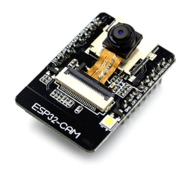
Compatible Hardware

ESP32 Cam by Espressif
ESP32-CAM as an EZB for Synthiam ARC: stream video, control GPIO/servos, AP/Client WiFi, and ARC D0-D23 to GPIO pin mapping.
Wi-Fi
Servos Varies
Camera
Audio
UART Varies
I2C
ADC Varies
Digital Varies

Description

This firmware converts a ESP32 Cam into an EZB for ARC to connect to it.

This firmware transforms an ESP32-based camera module into a full EZ-B-compatible controller with integrated Synthiam ARC video streaming. It enables the ESP32 to function simultaneously as a real-time camera and as a robotics/IoT peripheral controller - all in one compact board.

Summary

This firmware turns an ESP32 camera module into an ARC-compatible EZ-B controller with live video, digital I/O, ultrasonic measurement, and optional ADC support.

To deploy successfully you must:

  1. Select the correct CAMERA_MODEL_* define.
  2. Edit the mapping tables to match your ESP32 board’s GPIO.
  3. Flash the firmware and connect through Synthiam ARC.

Once mapped, the ESP32 behaves like a compact, Wi-Fi enabled, vision-equipped EZ-B controller ready for robotics and IoT applications.


Important note about PWM/actuators: If PWM output for actuators is required, use an external controller such as a PCA9685, SSC-32, or another dedicated PWM/servo driver. This is necessary due to the limited processing and I/O capability of ESP32 devices-especially camera-based modules. The camera subsystem consumes a significant amount of CPU time, DMA bandwidth, GPIOs, and LEDC timer resources, so PWM generation must be offloaded to a slave peripheral controller for reliable operation.


What the Firmware Provides

  1. EZ-B Compatibility The ESP32 accepts ARC control commands and behaves like an EZ-B, allowing digital outputs, ultrasonic sensors, and other peripherals to be controlled directly from Synthiam ARC.

  2. Integrated Camera Streaming The onboard OV2640 camera streams JPEG video to ARC, providing live visual feedback alongside peripheral control.

  3. Simultaneous Operation Camera streaming and peripheral control run together, making the ESP32 ideal for robotics scenarios where vision and control must happen at the same time.


Supported ESP32 Camera Boards

This firmware includes camera model definitions for many common modules, including variants of classic AI-Thinker style boards, M5Stack units, and ESP32-S2/S3 models with cameras.

Supported models include:

  • CAMERA_MODEL_AI_THINKER
  • CAMERA_MODEL_WROVER_KIT
  • CAMERA_MODEL_ESP_EYE
  • CAMERA_MODEL_M5STACK_PSRAM
  • CAMERA_MODEL_M5STACK_V2_PSRAM
  • CAMERA_MODEL_M5STACK_WIDE
  • CAMERA_MODEL_M5STACK_ESP32CAM
  • CAMERA_MODEL_M5STACK_UNITCAM
  • CAMERA_MODEL_M5STACK_CAMS3_UNIT
  • CAMERA_MODEL_TTGO_T_JOURNAL
  • CAMERA_MODEL_XIAO_ESP32S3
  • CAMERA_MODEL_ESP32_CAM_BOARD
  • CAMERA_MODEL_ESP32S3_CAM_LCD
  • CAMERA_MODEL_ESP32S2_CAM_BOARD
  • CAMERA_MODEL_ESP32S3_EYE
  • CAMERA_MODEL_DFRobot_FireBeetle2_ESP32S3
  • CAMERA_MODEL_DFRobot_Romeo_ESP32S3

Only one camera model should be enabled in the firmware at a time. A mismatched model typically results in "frame size = 0" or initialization errors.


Understanding GPIO Mapping (Very Important)

Different ESP32 camera boards have:

  • different exposed header pins
  • different analog capabilities
  • different LEDC PWM support
  • pins occupied by the camera bus (XCLK, PCLK, VSYNC, HREF, SDA/SCL, etc.)
  • differences between ESP32, ESP32-S2, ESP32-S3 variants

Because of this, ARC’s digital and ADC port numbers do NOT directly match ESP32 pin numbers. To solve that, the firmware uses mapping tables that translate between:

ARC Dx   -> ESP32 GPIO  
ARC ADCx -> ESP32 ADC-capable GPIO  

This mapping layer exists so that:

ARC always sees consistent "Dx" ports (0-23) regardless of hardware Camera-critical pins are never accidentally used for peripherals Different ESP32 board layouts remain compatible by changing only one mapping section PWM-capable pins are used only where supported Project code in ARC remains portable across ESP32 models


Editing the Mapping for Your ESP32 Module

You must customize the mapping arrays to reflect the physical pins on the ESP32 camera board you are using. This is the only hardware-specific part of the firmware.

This is how ARC ports and ESP32 parts are mapped. In the example below, ARC D0 is mapped to ESP32 port #2. Example of the concept for WRover with camera:

const uint8_t ARC_TO_ESP_DIGITAL_PIN_MAPPING[24] = {

  2,   // ARC port D0
  13,  // ARC port D1
  14,  // ARC port D2
  15,  // ARC port D3
  12,  // ARC port D4
  0xff, // ARC port D5 (not used)
  0xff, // ARC port D6 (not used)
  0xff, // ARC port D7 (not used)
  0xff, // ARC port D8 (not used)
  0xff, // ARC port D9 (not used)
  0xff, // ARC port D10 (not used)
  0xff, // ARC port D11 (not used)
  0xff, // ARC port D12 (not used)
  0xff, // ARC port D13 (not used)
  0xff, // ARC port D14 (not used)
  0xff, // ARC port D15 (not used)
  0xff, // ARC port D16 (not used)
  0xff, // ARC port D17 (not used)
  0xff, // ARC port D18 (not used)
  0xff, // ARC port D19 (not used)
  0xff, // ARC port D20 (not used)
  0xff, // ARC port D21 (not used)
  0xff, // ARC port D22 (not used)
  0xff  // ARC port D23 (not used)
};

const uint8_t ARC_TO_ESP_ADC_PIN_MAPPING[8] = {

  0xff, // ARC port ADC0 (not mapped)
  0xff, // ARC port ADC1 (not mapped)
  0xff, // ARC port ADC2 (not mapped)
  0xff, // ARC port ADC3 (not mapped)
  0xff, // ARC port ADC4 (not mapped)
  0xff, // ARC port ADC5 (not mapped)
  0xff, // ARC port ADC6 (not mapped)
  0xff  // ARC port ADC7 (not mapped)
};

// ----------------------------------------------------------------
// Serial Expansion UART Configuration (in ARC this is UART #0)
// ----------------------------------------------------------------
#define SERIAL2_RX 12
#define SERIAL2_TX 13

Where:

  • 0xFF = not available
  • Valid range = 0-23 for digital and 0-7 for ADC

This means ARC’s D0...D23 and ADC0...ADC7 stay consistent in software, even though the underlying ESP hardware changes.


How the Firmware Uses the Mapping

Once configured, ARC can:

Peripheral Control

  • Toggle digital outputs
  • Drive PWM-capable pins
  • Read ultrasonic distance
  • Poll analog inputs (if available)

Camera Streaming

  • Send JPEG frames via TCP
  • Auto-adjust compression based on frame size to prevent buffering issues

Resource Management

  • Reserves LEDC timer channels so PWM output can’t break camera clock timing
  • Manages Wi-Fi event handling for both AP and STA modes

Benefits of This System

Portable Projects ARC projects don’t need to change when switching ESP32 boards - only the mapping tables change.

Camera Safety Prevents peripherals from attaching to camera data lines and causing frame failures.

Better Hardware Compatibility Works with ESP32, ESP32-S2, and ESP32-S3 camera variants.

All-in-One Hardware Eliminates the need for a separate EZ-B and camera module.

Cost Effective Uses low-cost ESP32 hardware for high-level robotics and IoT tasks.


Typical Use Case

Perfect for robots or IoT devices needing combined vision + control, such as:

  • FPV robotic rovers
  • Mobile robots with live video feedback
  • Remote inspection robots
  • Home automation with visual monitoring
  • Telepresence devices

Downloads

Download

This release is a stability + performance architecture upgrade and rewrite:

  • Camera streaming is prioritized and less likely to stall
  • UART expansion no longer trashes camera timing
  • RX buffering is now large enough to absorb WiFi bursts without protocol starvation
  • RTOS scheduling is finally core-aware instead of hoping the scheduler behaves

This is a really solid foundation for the ESP32-CAM behaving like a proper EZ-B class device instead of a "best effort" WiFi peripheral.


  • Removed all servo support

    • Servo libraries, servo pin mappings, servo logic, and detach handling are gone
    • ESP32-CAM is now treated strictly as digital + ADC + UART + camera
  • FreeRTOS task core pinning added

    • EZB, Camera, and Broadcast tasks can now be pinned to specific CPU cores
    • Explicit core configuration macros added
    • Startup now logs available CPU cores
  • Task priority rebalanced

    • Camera task priority increased
    • EZB task priority reduced
    • Improves camera streaming stability under EZB protocol load
  • Massive EZB RX buffer upgrade

    • Switched from small fixed ring buffer to dynamically allocated 64 KB input buffer
    • Buffer now allocated from heap at startup with hard failure if allocation fails
    • Eliminates previous ring buffer overrun logic and dropped-byte behavior
  • Simplified EZB receive pipeline

    • Removed ring overwrite / drop logic
    • Input stream now behaves like a large linear buffer
    • Reduced overhead in socket draining
  • Serial2 (UART expansion) improvements

    • Configurable RX buffer size (8 KB)
    • Proper back-pressure handling when writing to Serial2
    • Reduced chance of camera lockups during UART transfers
    • More cooperative yielding during UART writes
  • Connection handling hardened

    • Only one EZB client allowed at a time
    • Only one Camera client allowed at a time
    • New incoming connections are actively rejected so listen backlog can’t clog
    • Explicit "already connected" response sent to rejected EZB clients
  • Camera server stability improvements

    • Camera client acceptance/rejection logic cleaned up
    • Prevents backlog fill and accidental client stomping
    • More predictable disconnect behavior
  • Network write performance improvements

    • Multi-byte writes batched instead of per-byte sends
    • Reduced syscall overhead on protocol responses
  • Reduced blocking / better task yielding

    • Replaced blocking delays with FreeRTOS-friendly yielding
    • Improves camera frame stability during heavy EZB traffic
  • Cleaner GPIO handling

    • GPIO mode handling simplified
    • Removed special-case servo pin behavior
    • Less chance of pin conflicts with camera pins
  • Device identity cleanup

    • Default device name simplified to ESP32CAM
  • Longer idle loop delay

    • Main Arduino loop now yields longer since all work is task-driven
Click to show supported capabilities
Supported Capabilities
  • 12 Byte Unique Identifier
    Each controller has a unique identifier that can be referenced. This is to keep track in EZ-Builder projects which controller is being used and user logic specific to the ID.
  • ADC with 12 bit Resolution
    The ADC captures analog voltage at 8 bit resolution. This means the native value will be an 8 bit (0-4095) from the controller.
  • Broadcasts to ARC's PnP network scanner
    Controller broadcasts itself on the network using the ARC PnP network scanner protocol. This is so ARC can find devices on the network which may have dhcp assigned addresses.
  • Can stream video v4 codec
    The controller supports the streaming Video v4 codec on a TCP or UART or USB connection.
  • Hardware UART TX/RX with DMA buffer and adjustable baud rate
    Contains 1 or more hardware UARTs with TX/RX functionality and DMA RX buffering.
  • Native WiFi Connectivity from ARC
    Controller supports WiFi connectivity using TCP between your computer with ARC.
  • PWM Duty on digital ports
    Digital ports can output a PWM between 0% and 100%.
  • PWM servos on digital ports
    The controller supports PWM Servos on digital ports. These are also called Hobby servos.
  • PWM servos on digital ports can release their position
    PWM servo driver on digital ports support the feature to release their holding position.
  • Read/Write Digital I/O Ports
    The ports marked as being digital will respond to Read and Write commands of boolean logic. The status of the digital port will be either TRUE or FALSE when voltage is detected or not, respectively.
  • Transmit Uart TX on all digital ports
    All digital ports support the ability to transmit (TX) serial/uart data at various pre-determined baud rates.
Download
  • FreeRTOS task separation for stability and performance

    • EZB (ARC protocol) processing now runs in its own high-priority task.
    • Camera streaming runs in a dedicated task to prevent video stalls during heavy EZB traffic.
    • EZ-B scan UDP broadcast runs in its own low-priority task for consistent discovery without impacting control or video.
  • Configurable UART pin mapping for EZB UART Expansion

    • UART RX/TX pins can now be explicitly assigned using the defines in the configuration section.
  • Servo outputs mapped to UART RX/TX pins are automatically detached to avoid PWM/UART contention.

  • Improved EZB TCP receive handling

    • Socket RX is aggressively drained into a ring buffer to prevent TCP window shrink and ARC command throttling.
    • Non-blocking RX pump using available() to avoid rare stalls or watchdog resets under heavy traffic.

Fixed

  • WiFiClient initialization bugs

    • Removed invalid WiFiClient = NULL usage that could cause undefined behavior or crashes.
    • Added proper connection validation before RX/TX operations.
  • Camera framebuffer lifetime handling

    • Ensures esp_camera_fb_return() is always called to prevent memory exhaustion and camera lockups.
  • Camera + PWM timer conflicts

    • Reserved LEDC timer for camera XCLK and restricted ESP32Servo to safe timers to prevent camera clock corruption.
  • UDP broadcast reliability

    • Uses subnet-directed broadcast instead of limited broadcast to improve EZB discovery on segmented networks and APs.

Performance Improvements

  • Reduced protocol parsing stalls by bounding EZB command processing per tick.
  • Lowered contention between camera streaming and EZB command bursts via task prioritization.
  • Improved camera compression stability using frame-window averaging to reduce visible flicker.

Internal / Refactoring

  • Centralized EZB protocol handling into a dedicated task.
  • Added task handles for debugging and runtime inspection.
  • Hardened WiFi reconnect behavior in client mode.
  • Added missing helpers for camera client lifecycle handling.

Notes

  • UART RX/TX pins must not overlap camera GPIOs for the selected camera model.
  • ESP32-WROVER users should prefer Serial2 for UART Expansion to avoid flash/PSRAM pin conflicts.
  • For best stability, keep EZB task priority higher than camera and broadcast tasks.
Click to show supported capabilities
Supported Capabilities
  • 12 Byte Unique Identifier
    Each controller has a unique identifier that can be referenced. This is to keep track in EZ-Builder projects which controller is being used and user logic specific to the ID.
  • ADC with 12 bit Resolution
    The ADC captures analog voltage at 8 bit resolution. This means the native value will be an 8 bit (0-4095) from the controller.
  • Broadcasts to ARC's PnP network scanner
    Controller broadcasts itself on the network using the ARC PnP network scanner protocol. This is so ARC can find devices on the network which may have dhcp assigned addresses.
  • Can stream video v4 codec
    The controller supports the streaming Video v4 codec on a TCP or UART or USB connection.
  • Hardware UART TX/RX with DMA buffer and adjustable baud rate
    Contains 1 or more hardware UARTs with TX/RX functionality and DMA RX buffering.
  • Native WiFi Connectivity from ARC
    Controller supports WiFi connectivity using TCP between your computer with ARC.
  • PWM Duty on digital ports
    Digital ports can output a PWM between 0% and 100%.
  • PWM servos on digital ports
    The controller supports PWM Servos on digital ports. These are also called Hobby servos.
  • PWM servos on digital ports can release their position
    PWM servo driver on digital ports support the feature to release their holding position.
  • Read/Write Digital I/O Ports
    The ports marked as being digital will respond to Read and Write commands of boolean logic. The status of the digital port will be either TRUE or FALSE when voltage is detected or not, respectively.
  • Transmit Uart TX on all digital ports
    All digital ports support the ability to transmit (TX) serial/uart data at various pre-determined baud rates.
Download

Camera capture pipeline

  • Removed OV2640 wrapper dependency

    • uses the native ESP-IDF camera API directly: esp_camera_init(), esp_camera_fb_get(), and esp_camera_fb_return().
  • Fixed/strengthened frame buffer lifecycle

    • always returns the framebuffer (esp_camera_fb_return(fb)) even on warnings/edge cases to prevent leaks/stalls.
  • More robust init error handling

    • checks the return value of esp_camera_init() and prints a helpful diagnostics block (wrong model define, ribbon cable, power, lowering clock, etc.) before halting.
  • JPEG quality bounds / alignment

    • clamps compression to 1..63 (ESP32 camera semantics)
  • PSRAM-aware framebuffer count

    • sets fb_count = 2 only if psramFound(), otherwise fb_count = 1 to reduce memory pressure.

Auto compression (ACOMP)

  • Refactored ACOMP logic into a dedicated function

    • introduces performAutoCompression(uint32_t imgSize) and calls it per frame.
  • Uses the same averaging approach, but is cleaner/less error-prone

    • accumulate _acomImgSizeSum/_acomImgSizeCount, compute average over ACOMPFRAMECNT, then adjust _compression by ACOMPSTEP within bounds.

GPIO / servo / pin-mode management

  • New pin-mode cache by GPIO number (0..254)

    • replaces the old _PIN_MODES[24] "GPIO index" cache with _GpioModeCache[255] keyed by actual GPIO number.
    • This avoids the incorrect assumption that GPIO numbers are always < 24.
  • Servo storage changed to per-ARC-port (instead of per-GPIO index)

    • Servo _ServosByArcPort[24];
  • Removed invalid "GPIO validity" model

    • removes that and instead:
      • detaches servos by ARC port
      • caches pinMode by actual GPIO value
  • Safer detach behavior when repurposing pins

    • adds detachServoByARCPort() and uses it before setting pins for GPIO/PWM reads/writes.

Camera pin conflict detection

  • Kept feature, improved positioning and clarity
    • include anyPinMatch() + verifyNoCameraPinConflict() to halt with a clear message if ARC mapping overlaps camera-required GPIOs.
    • places the comment block above verifyNoCameraPinConflict() explaining why it exists and what users should do.

WiFi / connectivity / streaming

  • More explicit camera warning case
    • warns when esp_camera_fb_get() returns null/empty, with more direct wording.
Click to show supported capabilities
Supported Capabilities
  • 12 Byte Unique Identifier
    Each controller has a unique identifier that can be referenced. This is to keep track in EZ-Builder projects which controller is being used and user logic specific to the ID.
  • ADC with 12 bit Resolution
    The ADC captures analog voltage at 8 bit resolution. This means the native value will be an 8 bit (0-4095) from the controller.
  • Can stream video v4 codec
    The controller supports the streaming Video v4 codec on a TCP or UART or USB connection.
  • Hardware UART TX/RX with DMA buffer and adjustable baud rate
    Contains 1 or more hardware UARTs with TX/RX functionality and DMA RX buffering.
  • Native WiFi Connectivity from ARC
    Controller supports WiFi connectivity using TCP between your computer with ARC.
  • PWM Duty on digital ports
    Digital ports can output a PWM between 0% and 100%.
  • PWM servos on digital ports
    The controller supports PWM Servos on digital ports. These are also called Hobby servos.
  • PWM servos on digital ports can release their position
    PWM servo driver on digital ports support the feature to release their holding position.
  • Read/Write Digital I/O Ports
    The ports marked as being digital will respond to Read and Write commands of boolean logic. The status of the digital port will be either TRUE or FALSE when voltage is detected or not, respectively.
  • Transmit Uart TX on all digital ports
    All digital ports support the ability to transmit (TX) serial/uart data at various pre-determined baud rates.
Download
  • Added a verification in the Setup() to check if there's a conflict between any camera pins and ARC_ESP32 mapping pins. The Digital, Servo, and ADC pins cannot be the same as those used in the Camera, otherwise there will be a peripheral conflict. The firmware will display a looping error message in the serial monitor if there is a pin conflict.

You have two options to resolve a conflict, but first, make sure you have selected the board settings that match your board.

Here are your options to rectify a pin conflict...

  1. View the datasheet/schematic or pinouts of the PCB and look for PINs that do not conflict with those listed for your module in camera_pins.h. Replace the conflicting PINs with the PINs you would like to use instead. For example, if pin #4 conflicts with servo or DIGITAL pin mapping, change it to a pin that is not already in use and available on the PCB.

  2. Remove the entry entirely by moving every pin value up and adding a 0xff at the end. There must always be 24 entries.

  3. If you don't care about organizing anything, replace the value with 0xff, and that ARC Dx pin will not do anything. But,  you'll end up with a value in the middle of your port range that doesn't do anything, which might be kinda weird.

Click to show supported capabilities
Supported Capabilities
  • 12 Byte Unique Identifier
    Each controller has a unique identifier that can be referenced. This is to keep track in EZ-Builder projects which controller is being used and user logic specific to the ID.
  • ADC with 12 bit Resolution
    The ADC captures analog voltage at 8 bit resolution. This means the native value will be an 8 bit (0-4095) from the controller.
  • Can stream video v4 codec
    The controller supports the streaming Video v4 codec on a TCP or UART or USB connection.
  • Hardware UART TX/RX with DMA buffer and adjustable baud rate
    Contains 1 or more hardware UARTs with TX/RX functionality and DMA RX buffering.
  • Native WiFi Connectivity from ARC
    Controller supports WiFi connectivity using TCP between your computer with ARC.
  • PWM Duty on digital ports
    Digital ports can output a PWM between 0% and 100%.
  • PWM servos on digital ports
    The controller supports PWM Servos on digital ports. These are also called Hobby servos.
  • PWM servos on digital ports can release their position
    PWM servo driver on digital ports support the feature to release their holding position.
  • Read/Write Digital I/O Ports
    The ports marked as being digital will respond to Read and Write commands of boolean logic. The status of the digital port will be either TRUE or FALSE when voltage is detected or not, respectively.
  • Transmit Uart TX on all digital ports
    All digital ports support the ability to transmit (TX) serial/uart data at various pre-determined baud rates.
Download

Compiling Instructions:

  • This was designed with.... Board: ESP32 by Espressif Systems Version 3.3.5 Library: ESP32Servo by Kevin Harrington Version 3.1.3

Camera & Image Pipeline

  • Switched to using the official esp_camera.h API alongside the OV2640 wrapper for improved compatibility with newer ESP32 camera cores.
  • Added configurable camera XCLK frequency via XCLOCK_FREQUENCY (#define), allowing selection between 20 MHz (default) and 10 MHz for long/poor-quality ribbon cables or noisy environments.
  • Zeroed the camera_config_t structure with memset() before use to ensure all new fields introduced by the ESP32 camera library start from a known state.
  • Added a robust check for esp_camera_sensor_get() returning nullptr and a descriptive error message to the Serial console, with a safe halt loop if the camera fails to initialize.
  • Added a confirmation log message when the camera initializes successfully.
  • Improved the auto-compression (ACOMP) logic:
    • Uses safer accumulation and division with guards for zero-frame conditions.
    • Casts image size and average size more defensively.
    • Keeps compression changes within a defined 5-60 range with an explicit target window around 7-8 KB per frame.
  • Ensured the camera’s LEDC timer (timer 3 / channel 7) is reserved exclusively for XCLK so servo PWM cannot accidentally reconfigure the camera clock.

WiFi & Network Behavior

  • Expanded WiFi event handling to cover the full WiFiEvent_t enum, including RSSI low, beacon timeout, remain-on-channel, WPS PBC overlap, and more, with detailed Serial logging.
  • Added a separate Arduino-layer IPEvent() handler for arduino_event_t, covering WiFi and Ethernet events (IPv4/IPv6 acquisition, connect/disconnect, AP events) with verbose Serial diagnostics.
  • Kept WiFi.setSleep(false) to prioritize low-latency streaming while documenting the trade-off with power consumption.
  • In AP mode, changed the default softAP IP from 192.168.50.1 to 192.168.1.1 for a more standard local network layout.
  • Preserved the ESP.restart() safety behavior in client mode when WiFi connectivity is lost, ensuring the device self-recovers.

ARC / ESP32 Pin Mapping

  • Introduced explicit mapping tables to decouple ARC logical ports from ESP32 GPIO numbers:
    • ARC_TO_ESP_DIGITAL_PIN_MAPPING[24]
    • ARC_TO_ESP_SERVO_PIN_MAPPING[24]
    • ARC_TO_ESP_ADC_PIN_MAPPING[8]
  • Documented that ARC has 24 digital/servo Dx ports and 8 ADC ports, with unmapped entries set to 0xff.
  • Reworked all digital, servo, PWM, ultrasonic, and ADC commands to use these mapping tables instead of assuming ARC port index == ESP32 GPIO number.
  • Added isArcPortValid() and isGpioValid() helpers to safely validate indices before touching arrays or GPIO, avoiding out-of-range access.

Servo / PWM Handling

  • Increased the _Servos array size to 24 and tied it to the mapped GPIO indices for more consistent ARC-to-ESP mapping.
  • Added a pin-mode cache (_PIN_MODES[24]) initialized to -1 at startup, so pin configuration is only applied when needed.
  • Added servo as a dedicated pin-mode value to distinguish servo-controlled pins from normal INPUT/OUTPUT.
  • Introduced guarding logic so that:
    • Setting digital outputs or PWM on a pin will detach any servo mapped to the same ARC port first.
    • Servo and digital usage no longer conflict silently on shared pins.
  • Limited ESP32Servo/ESP32PWM to use only LEDC timers 0, 1, and 2 so that timer 3 remains permanently reserved for the camera XCLK.

EZB Protocol & Command Handling

  • Kept the core EZB command set (ping, firmware ID, digital, servo, PWM, ultrasonic, ADC, UART expansion, etc.) but refactored the implementation to use the new ARC/ESP mapping tables.
  • CmdReleaseAllServos now iterates the ARC_TO_ESP_SERVO_PIN_MAPPING table and only detaches servos on mapped pins, avoiding touching unknown or invalid GPIOs.
  • Servo positioning (CmdSetServoPosition) now:
    • Validates ARC port range.
    • Looks up the mapped servo GPIO.
    • Uses servo pin mode and attach/detach behavior based on position, with bounds checking via isGpioValid().
  • PWM speed (CmdSetPWMSpeed) now:
    • Uses the servo mapping to find the GPIO used for PWM.
    • Detaches any servo on that GPIO before running analogWrite().
  • Digital on/off and digital read commands now:
    • Validate ARC ports.
    • Map through ARC_TO_ESP_DIGITAL_PIN_MAPPING and detach servos only if they share the same GPIO.
    • Enforce correct pin mode (INPUT/OUTPUT) via the pin-mode cache.
  • Ultrasonic (CmdHC_SR04) now:
    • Validates ARC ports.
    • Uses digital mapping for both trigger and echo.
    • Detaches any servos that share those GPIOs before triggering.
    • Works only on mapped, valid pins and still returns distance in cm as uint8_t.
  • ADC read (CmdGetADCValue) now:
    • Uses ARC_TO_ESP_ADC_PIN_MAPPING instead of a fixed switch statement.
    • Returns 0 for unmapped ADC ports or invalid mappings, with pin-mode setup only when a valid GPIO is configured.
  • Added an error(const char*) helper that prints a descriptive message in a tight loop when an invalid ARC port is detected for critical commands, making configuration issues very visible during development.

UART / Serial Enhancements

  • Switched to Serial2.setRxBufferSize(8000) for ESP32 core compatibility (replacing setRxBuffer()).
  • Kept readSerial2Byte() as a blocking helper that reads directly from Serial2, matching the previous behavior while simplifying the code.
  • Maintained the UART expansion commands for CmdEZBv4 (UARTExpansion0/1/2) but ensured they work cleanly with the new buffer configuration and mapping safety checks.

Internal Structure & Safety

  • Added explicit forward declaration of doEZProtocol() near the top of the file for clarity.
  • Converted several short utility functions (IsAvail, Avail, validity checks) to inline for performance in the tight main loop and protocol handler.
  • Replaced the EZ header globals with macros:
    • EZHEADER and EZHEADER_LEN
    • Simplifies use when writing the image prefix to the camera client.
  • When accepting new CAM and EZB clients, now use a temporary WiFiClient variable before assigning to the global to avoid partial or invalid states.
  • Improved comments and documentation throughout the file, especially around:
    • Camera configuration and troubleshooting.
    • ARC-to-ESP pin mapping behavior.
    • WiFi and Arduino event handling.
    • Expected behavior when port mappings are incorrect.

Behavioral Changes You May Notice

  • Default AP IP is now 192.168.1.1 instead of 192.168.50.1.
  • If the wrong CAMERA_MODEL_x is selected or the camera fails to initialize, the firmware now prints a clear error and halts instead of failing silently with zero-length frames.
  • Digital, servo, PWM, ultrasonic, and ADC operations are now mediated through explicit ARC mappings, making it easier to port this firmware to other ESP32-based boards by adjusting only the mapping tables.
  • Auto-compression of camera images should be more stable with fewer visible jumps in JPEG quality due to the guarded averaging logic.
Click to show supported capabilities
Supported Capabilities
  • 12 Byte Unique Identifier
    Each controller has a unique identifier that can be referenced. This is to keep track in EZ-Builder projects which controller is being used and user logic specific to the ID.
  • ADC with 12 bit Resolution
    The ADC captures analog voltage at 8 bit resolution. This means the native value will be an 8 bit (0-4095) from the controller.
  • Can stream video v4 codec
    The controller supports the streaming Video v4 codec on a TCP or UART or USB connection.
  • Hardware UART TX/RX with DMA buffer and adjustable baud rate
    Contains 1 or more hardware UARTs with TX/RX functionality and DMA RX buffering.
  • Native WiFi Connectivity from ARC
    Controller supports WiFi connectivity using TCP between your computer with ARC.
  • PWM Duty on digital ports
    Digital ports can output a PWM between 0% and 100%.
  • PWM servos on digital ports
    The controller supports PWM Servos on digital ports. These are also called Hobby servos.
  • PWM servos on digital ports can release their position
    PWM servo driver on digital ports support the feature to release their holding position.
  • Read/Write Digital I/O Ports
    The ports marked as being digital will respond to Read and Write commands of boolean logic. The status of the digital port will be either TRUE or FALSE when voltage is detected or not, respectively.
  • Transmit Uart TX on all digital ports
    All digital ports support the ability to transmit (TX) serial/uart data at various pre-determined baud rates.
Download
  • Removed firmware-level Serial2 RX ring buffer and switched to ESP32 UART hardware buffer (setRxBuffer(8000)).
  • Updated UART expansion commands to read/write directly from Serial2.
  • Removed unused Serial2 buffer code and related helper functions.
  • Minor code cleanup and simplification around UART handling.
  • Digital read fix: CmdGetDigitalPort previously returned the port index instead of the actual digital pin state - now correctly returns digitalRead(port).
  • Camera/EZB client IP logging fix: Printed _CLIENT.remoteIP() before assigning the client object - corrected to log after available().
  • HSR04 bounds check fix: Port range check used <= _PortCnt (off-by-one) - corrected to < _PortCnt since _PortCnt is a count, not last index.
Click to show supported capabilities
Supported Capabilities
  • 12 Byte Unique Identifier
    Each controller has a unique identifier that can be referenced. This is to keep track in EZ-Builder projects which controller is being used and user logic specific to the ID.
  • ADC with 12 bit Resolution
    The ADC captures analog voltage at 8 bit resolution. This means the native value will be an 8 bit (0-4095) from the controller.
  • Can stream video v4 codec
    The controller supports the streaming Video v4 codec on a TCP or UART or USB connection.
  • Hardware UART TX/RX with DMA buffer and adjustable baud rate
    Contains 1 or more hardware UARTs with TX/RX functionality and DMA RX buffering.
  • Native WiFi Connectivity from ARC
    Controller supports WiFi connectivity using TCP between your computer with ARC.
  • PWM Duty on digital ports
    Digital ports can output a PWM between 0% and 100%.
  • PWM servos on digital ports
    The controller supports PWM Servos on digital ports. These are also called Hobby servos.
  • PWM servos on digital ports can release their position
    PWM servo driver on digital ports support the feature to release their holding position.
  • Read/Write Digital I/O Ports
    The ports marked as being digital will respond to Read and Write commands of boolean logic. The status of the digital port will be either TRUE or FALSE when voltage is detected or not, respectively.
  • Transmit Uart TX on all digital ports
    All digital ports support the ability to transmit (TX) serial/uart data at various pre-determined baud rates.
Download
  1. Install libraries into arduino ide: https://dl.espressif.com/dl/package_esp32_index.json

  2. Board manager install ESP32 by Espressif Systems

This project builds using...

  • Espressif Systems esp32 library version 3.0.7
  • ESP32Servo by Kevin Harrington version 3.0.6
Click to show supported capabilities
Supported Capabilities
  • 12 Byte Unique Identifier
    Each controller has a unique identifier that can be referenced. This is to keep track in EZ-Builder projects which controller is being used and user logic specific to the ID.
  • ADC with 12 bit Resolution
    The ADC captures analog voltage at 8 bit resolution. This means the native value will be an 8 bit (0-4095) from the controller.
  • Can stream video v4 codec
    The controller supports the streaming Video v4 codec on a TCP or UART or USB connection.
  • Hardware UART TX/RX with DMA buffer and adjustable baud rate
    Contains 1 or more hardware UARTs with TX/RX functionality and DMA RX buffering.
  • Native WiFi Connectivity from ARC
    Controller supports WiFi connectivity using TCP between your computer with ARC.
  • PWM Duty on digital ports
    Digital ports can output a PWM between 0% and 100%.
  • PWM servos on digital ports
    The controller supports PWM Servos on digital ports. These are also called Hobby servos.
  • PWM servos on digital ports can release their position
    PWM servo driver on digital ports support the feature to release their holding position.
  • Read/Write Digital I/O Ports
    The ports marked as being digital will respond to Read and Write commands of boolean logic. The status of the digital port will be either TRUE or FALSE when voltage is detected or not, respectively.
  • Transmit Uart TX on all digital ports
    All digital ports support the ability to transmit (TX) serial/uart data at various pre-determined baud rates.
Download

Version Information

  • Added editable definitions at the top of the ino source file for enabling/disabling features
Click to show supported capabilities
Supported Capabilities
  • 12 Byte Unique Identifier
    Each controller has a unique identifier that can be referenced. This is to keep track in EZ-Builder projects which controller is being used and user logic specific to the ID.
  • ADC with 12 bit Resolution
    The ADC captures analog voltage at 8 bit resolution. This means the native value will be an 8 bit (0-4095) from the controller.
  • Can stream video v4 codec
    The controller supports the streaming Video v4 codec on a TCP or UART or USB connection.
  • Hardware UART TX/RX with DMA buffer and adjustable baud rate
    Contains 1 or more hardware UARTs with TX/RX functionality and DMA RX buffering.
  • Native WiFi Connectivity from ARC
    Controller supports WiFi connectivity using TCP between your computer with ARC.
  • PWM Duty on digital ports
    Digital ports can output a PWM between 0% and 100%.
  • PWM servos on digital ports
    The controller supports PWM Servos on digital ports. These are also called Hobby servos.
  • PWM servos on digital ports can release their position
    PWM servo driver on digital ports support the feature to release their holding position.
  • Read/Write Digital I/O Ports
    The ports marked as being digital will respond to Read and Write commands of boolean logic. The status of the digital port will be either TRUE or FALSE when voltage is detected or not, respectively.
  • Transmit Uart TX on all digital ports
    All digital ports support the ability to transmit (TX) serial/uart data at various pre-determined baud rates.
Download

Version Information

  • Increase the auto compression adjustment jump from 1 to 5 so it responds quicker.
Click to show supported capabilities
Supported Capabilities
  • 12 Byte Unique Identifier
    Each controller has a unique identifier that can be referenced. This is to keep track in EZ-Builder projects which controller is being used and user logic specific to the ID.
  • ADC with 12 bit Resolution
    The ADC captures analog voltage at 8 bit resolution. This means the native value will be an 8 bit (0-4095) from the controller.
  • Can stream video v4 codec
    The controller supports the streaming Video v4 codec on a TCP or UART or USB connection.
  • Hardware UART TX/RX with DMA buffer and adjustable baud rate
    Contains 1 or more hardware UARTs with TX/RX functionality and DMA RX buffering.
  • Native WiFi Connectivity from ARC
    Controller supports WiFi connectivity using TCP between your computer with ARC.
  • PWM Duty on digital ports
    Digital ports can output a PWM between 0% and 100%.
  • PWM servos on digital ports
    The controller supports PWM Servos on digital ports. These are also called Hobby servos.
  • PWM servos on digital ports can release their position
    PWM servo driver on digital ports support the feature to release their holding position.
  • Read/Write Digital I/O Ports
    The ports marked as being digital will respond to Read and Write commands of boolean logic. The status of the digital port will be either TRUE or FALSE when voltage is detected or not, respectively.
  • Transmit Uart TX on all digital ports
    All digital ports support the ability to transmit (TX) serial/uart data at various pre-determined baud rates.
Download

Version Information

  • Works with servo & Camera at the same time
  • Added a note that the default IP address in AP Mode is (192.168.50.1)
Click to show supported capabilities
Supported Capabilities
  • 12 Byte Unique Identifier
    Each controller has a unique identifier that can be referenced. This is to keep track in EZ-Builder projects which controller is being used and user logic specific to the ID.
  • ADC with 12 bit Resolution
    The ADC captures analog voltage at 8 bit resolution. This means the native value will be an 8 bit (0-4095) from the controller.
  • Can stream video v4 codec
    The controller supports the streaming Video v4 codec on a TCP or UART or USB connection.
  • Hardware UART TX/RX with DMA buffer and adjustable baud rate
    Contains 1 or more hardware UARTs with TX/RX functionality and DMA RX buffering.
  • Native WiFi Connectivity from ARC
    Controller supports WiFi connectivity using TCP between your computer with ARC.
  • PWM Duty on digital ports
    Digital ports can output a PWM between 0% and 100%.
  • PWM servos on digital ports
    The controller supports PWM Servos on digital ports. These are also called Hobby servos.
  • PWM servos on digital ports can release their position
    PWM servo driver on digital ports support the feature to release their holding position.
  • Read/Write Digital I/O Ports
    The ports marked as being digital will respond to Read and Write commands of boolean logic. The status of the digital port will be either TRUE or FALSE when voltage is detected or not, respectively.
  • Transmit Uart TX on all digital ports
    All digital ports support the ability to transmit (TX) serial/uart data at various pre-determined baud rates.
Download

Version Information

  • Works with servos & camera at the same time
Click to show supported capabilities
Supported Capabilities
  • 12 Byte Unique Identifier
    Each controller has a unique identifier that can be referenced. This is to keep track in EZ-Builder projects which controller is being used and user logic specific to the ID.
  • ADC with 12 bit Resolution
    The ADC captures analog voltage at 8 bit resolution. This means the native value will be an 8 bit (0-4095) from the controller.
  • Can stream video v4 codec
    The controller supports the streaming Video v4 codec on a TCP or UART or USB connection.
  • Hardware UART TX/RX with DMA buffer and adjustable baud rate
    Contains 1 or more hardware UARTs with TX/RX functionality and DMA RX buffering.
  • Native WiFi Connectivity from ARC
    Controller supports WiFi connectivity using TCP between your computer with ARC.
  • PWM Duty on digital ports
    Digital ports can output a PWM between 0% and 100%.
  • PWM servos on digital ports
    The controller supports PWM Servos on digital ports. These are also called Hobby servos.
  • PWM servos on digital ports can release their position
    PWM servo driver on digital ports support the feature to release their holding position.
  • Read/Write Digital I/O Ports
    The ports marked as being digital will respond to Read and Write commands of boolean logic. The status of the digital port will be either TRUE or FALSE when voltage is detected or not, respectively.
  • Transmit Uart TX on all digital ports
    All digital ports support the ability to transmit (TX) serial/uart data at various pre-determined baud rates.
Download

Version Information

  • added dynamic camera compression

  • mapped Dx to GPIOx (i.e. ARC D4 = GPIO4, which is the FLASH LED)

Click to show supported capabilities
Supported Capabilities
  • 12 Byte Unique Identifier
    Each controller has a unique identifier that can be referenced. This is to keep track in EZ-Builder projects which controller is being used and user logic specific to the ID.
  • ADC with 12 bit Resolution
    The ADC captures analog voltage at 8 bit resolution. This means the native value will be an 8 bit (0-4095) from the controller.
  • Can stream video v4 codec
    The controller supports the streaming Video v4 codec on a TCP or UART or USB connection.
  • Hardware UART TX/RX with DMA buffer and adjustable baud rate
    Contains 1 or more hardware UARTs with TX/RX functionality and DMA RX buffering.
  • Native WiFi Connectivity from ARC
    Controller supports WiFi connectivity using TCP between your computer with ARC.
  • PWM Duty on digital ports
    Digital ports can output a PWM between 0% and 100%.
  • PWM servos on digital ports
    The controller supports PWM Servos on digital ports. These are also called Hobby servos.
  • PWM servos on digital ports can release their position
    PWM servo driver on digital ports support the feature to release their holding position.
  • Read/Write Digital I/O Ports
    The ports marked as being digital will respond to Read and Write commands of boolean logic. The status of the digital port will be either TRUE or FALSE when voltage is detected or not, respectively.
  • Transmit Uart TX on all digital ports
    All digital ports support the ability to transmit (TX) serial/uart data at various pre-determined baud rates.
Download

Version Information

  • First check-in of the ESP32 Cam firmware

*Note: For servo use with EZ-Cam, only pins 2,4,12-19,21-23,25-27,32-33 are recommended.

Click to show supported capabilities
Supported Capabilities
  • 12 Byte Unique Identifier
    Each controller has a unique identifier that can be referenced. This is to keep track in EZ-Builder projects which controller is being used and user logic specific to the ID.
  • ADC with 12 bit Resolution
    The ADC captures analog voltage at 8 bit resolution. This means the native value will be an 8 bit (0-4095) from the controller.
  • Can stream video v4 codec
    The controller supports the streaming Video v4 codec on a TCP or UART or USB connection.
  • Hardware UART TX/RX with DMA buffer and adjustable baud rate
    Contains 1 or more hardware UARTs with TX/RX functionality and DMA RX buffering.
  • Native WiFi Connectivity from ARC
    Controller supports WiFi connectivity using TCP between your computer with ARC.
  • PWM Duty on digital ports
    Digital ports can output a PWM between 0% and 100%.
  • PWM servos on digital ports
    The controller supports PWM Servos on digital ports. These are also called Hobby servos.
  • PWM servos on digital ports can release their position
    PWM servo driver on digital ports support the feature to release their holding position.
  • Read/Write Digital I/O Ports
    The ports marked as being digital will respond to Read and Write commands of boolean logic. The status of the digital port will be either TRUE or FALSE when voltage is detected or not, respectively.
  • Transmit Uart TX on all digital ports
    All digital ports support the ability to transmit (TX) serial/uart data at various pre-determined baud rates.

ARC Pro

Upgrade to ARC Pro

Discover the limitless potential of robot programming with Synthiam ARC Pro – where innovation and creativity meet seamlessly.

Author Avatar
PRO
USA
#2  

It's not really a good cam at all. Bought one that was a great deal (less then $5.00 from Aliexpress) about 6 months back. Couldn't get it to focus right, thought it was bad so purchased just another camera, less the ESP32, same thing. It's ok if you want to use it for a stationary shot but terrible on anything that moves. I found it to be a great cam to monitor my 3D printer over my phone. If the focus is not good you can cut the small glue mark that's around the lens and then turn the lens to focus on the spot you need. If that makes sense?

Author Avatar
PRO
Canada
#4  

I agree not brilliant camera but it is very small, self contained, wireless and all you need to provide is power.  Good enough for Computer vision and object tracking (what I need it for). If we can also use the GPIO pins to control servo's or read sensors even better and you connect direct to It just like an EZB.

I plan to have 4 of these on my robot 1 inside each hand (So I can identify objects, orientate to the alignment of that object and position hand to grab that object based on orientation. Also plan to put some on feet to know when am about to trip and fall, align to kick a ball etc.

Author Avatar
PRO
Synthiam
#5  

The ezb mode does use gpio for digital and servos. every esp uses different pins for the camera, making it non-standard across different versions. Like all open source and low cost items like this, there’s no standard for us to implement. You’ll need to check the camera pinout file to see what pins are being used by the camera.

additionally, the gpio numbers relate to ARC Dx ports. So look at the diagram on the hardware page and those "should" work. But again, there’s no standard across esp32 cam versions.

You’d need to...

  1. look at the hardware page and the pinout diagram: https://synthiam.com/Support/Hardware/ESP32-Cam

  2. check in the firmware what type of camera you’re using (the #define statement that’s uncommented that works for you)

  3. use that type of camera to look at the camera pinout file included in the firmware and compare which pins are being used for the camera

Author Avatar
PRO
Canada
#6  

For the Ai Thinker it looks like I need to brush up on my soldering skills as they decided to put the pins used by the camera on the header and not the free pins.   https://github.com/raphaelbs/esp32-cam-ai-thinker/blob/master/docs/esp32cam-pin-notes.md You can still get access to the pins directly on the main board but this could be a bit of a nightmare. If I can't find 5 free pins I wonder if I can add a small ATTiny using serial connection back to ESP32-CAM https://embedded-lab.com/blog/wp-content/uploads/2015/12/8048281449822227147.jpg

User-inserted image

Author Avatar
PRO
Synthiam
#7  

Wow that’s a poor design LOL. In the words of AVGN... "what were they thinking?!"

Author Avatar
PRO
Canada
#8  

Reading the forums others have been tackling this problem.

apparently, have not tested yet,  GPIO0 is only used for enabling flashing firmware l, So this is free.

You can use TX & RX and this gives you GPIO 1 & 3

Put SD card in 1 bit mode with command  SD_MMC.begin("/sdcard", true) This gives access to 12 &13

You can use GPIO 4 but flash still goes off when you use it.

So this should free GPIO0, GPIO1, GPIO3, GPIO12, GPIO13 and GPIO4 flashing camera light when using.

https://www.esp32.com/viewtopic.php?t=13141

https://esp32.com/viewtopic.php?t=11471