
Good Morning Ez-Robot Community.
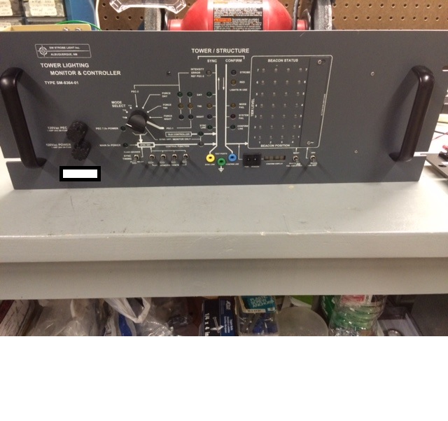
I would like to introduce myself. My daytime job is a Television Broadcast Engineer. The signal that is broadcasted comes from a 2000 ft tall tower. This tall tower has a total of 19 strobe lights, that is controlled by controller. The original controller that was made circa 1970 finally passed on. A new controller was purchased. This new controller has outputs that signal when a light on the tower is out. I was given the task to create a way to monitor the system remotely. I did a lot of digging, and found the Ez-b v4 controller. I gotta say, from design and building and to coding, this has to be the easiest platform I have ever worked with.
I have attached a few pictures below.
By WayneA.
— Last update
Discover more robots

Toymaker's When The Altair Ez:1 Met Pepper
ALTAIR EZ:1 meets Pepper robot for a European documentary; film crew captures their friendly interactions and 'bot...

Lumpy's Lumpy's Wall-E
Custom Wall-E robot build with servo-mounted eyes, mini-servos for arms, sonar installed, reinforced head mount and...
DJ's Hasbro R2d2 Hacked With Iotiny
Upgraded Comic Expo robot hack powered by EZ-B IoTiny with v4 camera vision, LED animations, motor controller, HDD...

That's awesome! Super cool to see another use for it!
Wowzers! That looks rather professional Wayne, thanks for sharing! If you have time to share more about your project I'd like see how you created the interface between tower strobes and EZB. And the feed back method to know if a light is out would be interesting too, is it some sort of light sensor used or a type of capacitance sensor?
wow!
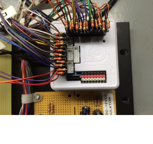
For your final setup, you should invest in a proper connector to the EZB or design a custom pcb, all those resistors plus wires can be a recipe for a short circuit
your are using a cannon (ARC) to kill a fly
if you have some developer skills you can build a custom firmware for the EZB, and the system will work without a PC.
Thank You @MazeHorizonTech and @JustinRatliff for the kind words!
@JustinRatliff: To answer your question each tower light has a 4 foot long strobe light (tube). Inside this cavity are more control boards and other electronics. As far as I understand how it works is, there is one line that is outputted, and all the lights talk to the controller over this one line.
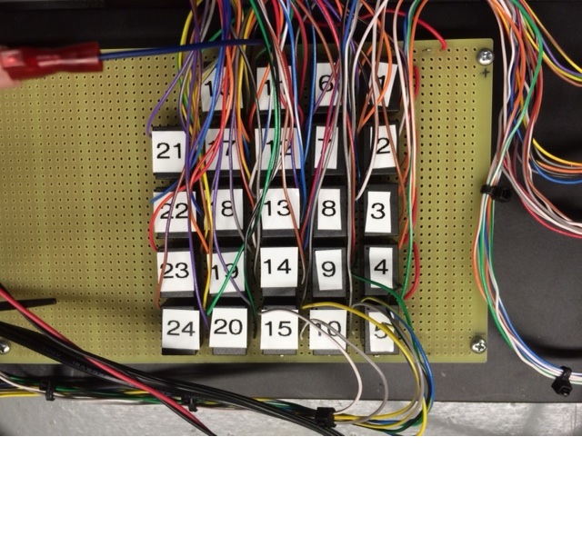
The light controller has built in monitor outputs for the strobe lights. If the controller senses an issue with any light, the controller grounds the failing output (relay labeled 1-24). I used that with the available 36VDC power supply on the controller to DC-DC convert to 12VDC to power the relays. I then used the normally open contacts to apply a voltage to the EZB.
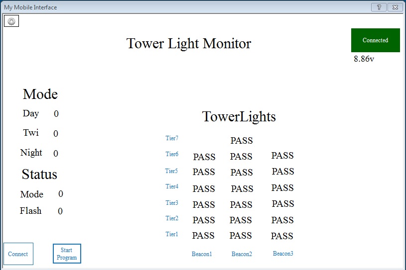
Then I used the code to read the status of that digital input as a 0 or 1. 0 is good, 1 is bad. in my case I converted to a pass or fail using a lot of if then statements.
I will need to clean up some of that code and I might need to use an array. That will take me some time. I literally had the code up and working in less that two hours.
Hope that answers your question.
Very cool Check out the code i posted in your other thread. It will trigger only when a state has changed. I believe it is what you're looking for.
@ptp I am not a code writer... yet. To formulate a response on the short circuit, I used a method of precise soldering.... and lots of zip ties.
What I would LOVE to do is to create custom circuit board that just simply plugs into the top of the EZB. That would be awesome!
As far as the custom firmware, that would be awesome, but the status needs to be monitored by humans.
Above is a picture of that the operator will see. The mobile interface is really cool. I am glad that it was available for me to use.
look how far you got... congratulations!
@ptp Thanks!