Omnimc

mattbrailsford

United Kingdom
robot video thumbnail

Hey Guys,

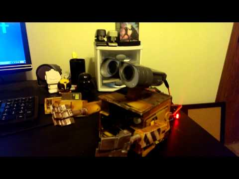
I've read lots on the forum, and posted a hand full of times, but I thought it was about time I launched my first major project (well, my second really, I converted a wall-e, but I thought there was enough of those on here :)).

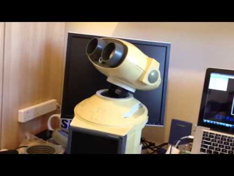
So here is announcing OmniMC, an Omnibot 2000 media centre :)

User-inserted image

The idea is to make him all RC and to also house a Raspberry PI running RaspBMC as the media centre bit. I'll then add some speakers and maybe some under-bot lighting :)

I'm wondering if then I can control the whole thing with one of these:

Cideko AVK08

Other than that, I'm kinda just winging it and seeing what other bits and pieces I come up with.

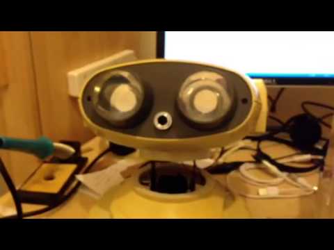
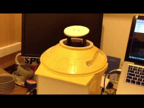
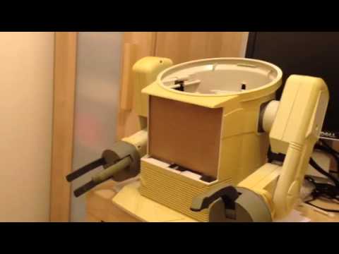
To start with though, I've done the usual thing of gutting him and sticking him through the dishwasher

User-inserted image User-inserted image

So right now, he is prepped and ready to go.

I've already got my EZ-Robot kit, and a few components such as 6v battery

Power Sonic 6v Battery

Some blue replacement bulbs

Blue Bulbs

My Raspberry PI (which arrived today) and I've just won a screen for his chest :)

Veba TFT LCD Monitor

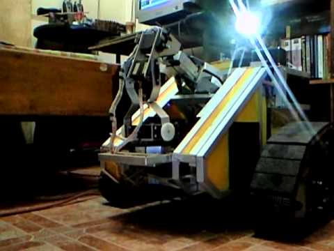
While I'm waiting for some other bits, I've also been looking at making some replacement tires which you can see details of in one of my other posts

Omni2k Wheels

So that's pretty much the state of play at the moment. I'm pretty much a novice at all this, so I'm looking forward to the challenge. Lets see if I've bitten off more than I can chew :)

By — Last update

ARC Pro

Upgrade to ARC Pro

Subscribe to ARC Pro, and your robot will become a canvas for your imagination, limited only by your creativity.

Germany
#1  

Hi Matt, do you happen to need the remote control or circuit board? Regards, Mike

#2  

Matt, it looks like you have things under control.

United Kingdom
#3  

Hey Mike,

Unfortunately it didn't come with a remote (it came with a fascia for a remote, but not a actual complete remote).

I don't need any of the internals if you need anything from there? though there was a scorch mark on the top of the plastic between the main circuit and the tape deck, so am thinking that it might have burnt out (was under where a big chip sits). The only bit I have that I think might be re-usable/saleable would be the tape deck and probably the LCD + panel, though again, because it wasn't in working condition when I got it, I can't guarantee anything.

United Kingdom
#4  

Whoop! The screen for his chest just arrived and it looks like it will fit perfectly :)

User-inserted image

Unfortunately I'm out tonight, so will have to wait till tomorrow till I get to play with it.

The screen itself has a weird connector on the bottom, but came with a wire harness that has the more standard RCA connectors, so I'll look to just gut the whole thing down and solder it on permanently. I should then be able to just hook it up to the raspberry pi, which is configured and ready to go :)

Once I have it working, the next step is figuring out how to mount it. I could just stick it on the front, but would be cool if I could make a cut out for it. I'm not sure how confident at doing that I am though. Anybody any tips?

Matt

United Kingdom
#5  

Ok, well, as I knew I couldn't play with it this evening, I thought I'd spend my lunch time giving it a quick test :)

User-inserted image

User-inserted image

Looks like I might have to create a custom skin for the UI as the fonts are really hard to read, but will look at that last (Not sure how much I should post about that here seeing as that is raspberry pi based, so will keep it to a minimum unless people ask).

Germany
#6  

Hi Matt, Great looking monitor! Regards, Mike

United Kingdom
#7  

Thanks Mike.

So with a little bit of soldering this morning, I managed to get the wiring down to this:

User-inserted image

A lot cleaner:) I kept the audio RCA jacks just incase I ever decide to connect them up, but have just wrapped them up and cable tied them for now.

United Kingdom
#8  

Ok, so last night I went ahead and cut the hole for the monitor

User-inserted image

I may have cut the sides a little too deep though

User-inserted image

I'm thinking though, maybe put masking tape around the monitor edge and fill in the gap with some body filler. Does that sound like a good idea? I've not really done that before though, so any tips / suggestions?

The next thing to work out is how to fix the screen into place

User-inserted image

Because of the cable coming out of the bottom (though I could move it) it currently needs to be mounted from the rear. I would like to try and keep it so that the screen could be removed should I need to, so I'm not too sure on a good way to mount it. Anybody got any suggestions?

United Kingdom
#9  

I've given it a bit of thought and I've modified the screen so that I can mount the screen from the front

User-inserted image

This notch will allow me to move the cable out of the way whilst putting the screen in place.

My thought now then is to glue / epoxy a strip of plastic to the inside of the bot shell inline with the back of the screen which will act as a stop for the screen and allow me to either double side / velcro / bolt the screen to it.

User-inserted image

Germany
#10  

You could ask josh aka jstarne about filling the gaps.he is pretty much spezialized in stuff like that. How is the viewing angle of your monitor? Maybe you want to tilt it a bit towards you so that you can actually see something when looking down on omnimc.

Germany
#11  

Btw: i think the screen fits perfectly! Its right the size to fill up the entire front. Not an inch wasted!

United Kingdom
#12  

Hey Mike. Good thinking on the viewing angle, I'll give it a test latter tonight. Yea, I was really pleased when I offered it up and it fit perfectly. All my hours of searching on ebay weren't in vain then :)

United Kingdom
#13  

I thought I'd try out the back stop for the monitor by using some cardboard and it works great

User-inserted image

There is plenty of gap below it to feed the wires through, and it keeps the monitor at the right distance. Next step then is to cut the same piece out of plastic, and epoxy it in place.

Whilst doing this, I've also swapped out the lense for the eyes, as I'm gonna do the usual thing of making his eyes blue (or am also tempted to have colour changing eyes to show his mood :)).

User-inserted image

I basically picked up a cheap box from my diy store and drew around the originals then cut them out with my dremel

User-inserted image

User-inserted image

They have a slight fogginess to them which is cool, but if I find the bulb is too bright in the centre, I'm thinking of cutting a circle of glass etch film (the type you put on your bathroom windows for privacy) and sticking it in the centre to diffuse it a little.

Canada
#14  

Looking good.

I cut up plastic milk jugs for a "etched glass" for lenses. It diffuses the LED's pretty good.

United Kingdom
#15  

Oooh, good thinking. I'll give that a go, thanks for the tip :)

United Kingdom
#16  

Hmm, am I being dumb? or does this wiring not make sense?

User-inserted image

So the two green wires go to the centre pins for the 2 bulbs, and the black wire goes from the outer screw of one bulb to the outer screw of the other bulb.

So no matter how you supply power, it doesn't make a circuit? Am I missing something?

Matt

#17  

I really like the work you are doing on this. It is a nice build.

Canada
#18  

If the bulbs are incandescent then polarity at the bulb end does not matter, so it is just a simple series circuit, wired strangely, but working. Typical incandescent bulbs have one end of the filament in the center and the other on the casing.

But you would have to redo the wiring for proper polarity if you want to use LEDs... you could probably just wire each LED separately so you could have it "blink" an eye.

United Kingdom
#19  

Thanks gunner. That makes sense. I'll go about rewiring it then.

Matt

United Kingdom
#20  

Ok, so time for the obligatory LED wiring question. So i have 2 bulbs which are 6v with a 20ma draw which i will connect to a 6v battery. I intend to connect them in paralel, so used a calculator to work out the resistors needed which comes out at 0ohms or 1ohm when rounding up. So, the question is, is a 1 ohm resistor really going to do / protect anything? Ive searched around and there seems to be a split of opinion.

Anyone got any compelling reasons for / against?

United Kingdom
#21  

I thought I'd just test it without resistors for the time being, so here are the test shots

User-inserted image User-inserted image I think it may be a tad bright straight on, so I might look at diffusing the light. I'm wondering if mirrored window tint film could be a good option? Dimming the light in the centre, but reflecting it back to bounce around the inner mirrors making them a bit brighter from the side viewing angle.

Canada
#23  

Adding in a resistor (depending on value, enough to drop voltage draw to 5v for example) will give a lower current draw, potential longer LED life and some control over the brightness.

You could also briefly dip the LEDs into acetone as that should etch the lens and give you LED diffusion but still allow full reflector value.

United Kingdom
#24  

Regarding the lights, I've thrown in a couple of 1ohm resistors as the online calculators say. Didn't make a huge difference, so can't see the harm in them being there.

Whilst I'm waiting on some other stuff, I've been pondering how to do the arms to be powered by servos. The thing I would really like to do though is to try and use the 3 large gears in the upper arm to keep the lower arm parallel to the ground (ie lower arms always horizontal regardless of the angle of the upper arm). I've been playing, and I think there is an interesting possibility which I've mocked up in the following shot:

User-inserted image The idea is to reuse one of the smaller gears from the upper arm to attach to the servo which is in turn mounted inside the arm. When the servos turns then, it forces the arm up in much the same way as the original motors did. The only issues I can foresee are 1) how to mount the servo 2) how to mount the gear and 3) from my tests, it would require the servo to be able to do almost a full 360 to have a decent range of motion.

If number 3 is a real big issue, it could be possible to design a custom gear and get it fabricated online (Shapeways or something).

What do people think? Any suggestions on the 3 issues?

Germany
#25  

Doesnt the ez kit supply the 360 degrees servos? If you want to use your own stronger servo, i am sure you can make it to a 360 degrees servo. Hasnt dj even put up a video for that...?

Germany
#26  

P.s. This picture doesnt make it easy to think about a solution for mounting the servo. Could you put up the opposite half of the arm? From this point of view, it just looks like you will have to make a bit of room for the servo, thus dremel a hole into the inner upper arm. What do you think?

Germany
#27  

One more thought: how easy is it to move your servo manually. I am just thinking, in the original concept of the arm, the gears not only made loud noise but also keep the arm steady in whatever position it was, sorta like a break. Lets say you put your servo in with just one or two gears in between - and let the robot hold something like a heavy glas in its hand, will the arm remain in its , lets say outstrettched, position or will it slwoly move down, because of the gears and servo not preventing it from doing so? Just a thought.....

United Kingdom
#28  

Hey mike, the small gear in the picture currently is too large, but I would cast / cut it down so it fits flush (it actually needs to meet up with a slightly smaller gear on the underside of the larg one you can see). I'll try and take some other shots to show what I'm thinking.

Regarding the arms ability to hold a load, I'm really not sure, so would have to try it and see really. The main aim is just to try and reuse the upper / lower arm linkage so I don't have to have a) more servos or b) something external to do the same job.

United Kingdom
#29  

Man, thinking of how best to do the arms has been doing my head in:) I'm also wondering whether something could be fashioned in a similar vain to how the omnibot arms work using some metal rods.

In the mean time though, I've added some reflective disks to the inside of his eyes to soften the light when looking straight on. I think it's a slight improvement, and what is cool is that the disks are silver, so when the lights aren't on, you hardly notice them, as the blend into the reflective backing.

User-inserted image

User-inserted image

I've also started work on the head pan / tilt mechanism. I'm using one of these from ebay which the guys said should take up to 2lbs of weight. I've compared these to the c brackets from lynxmotion too and it is a little thicker, so hopefully that'll add to it's robustness.

User-inserted image

User-inserted image

These show it offered up and a test piece installed to see how it all fits. The pan tilt mech is a lot taller than the usual lynxmotion ones, but it actually makes it fit almost exactly to the original neck height, which is lucky :)

User-inserted image

User-inserted image

These images show a widened neck hole on the torsoe, and a slimmer neck on the head + screw posts removed ready for filling.

I've got some filler and fiberglass on order, so that will be the next bit to do.

The last thing I've done is just marked up where the camera will go

User-inserted image

So some small, disjointed updates, but progress non the less :)

#30  

Great progress actually. And very nice work. I am anxious to see how well that pan/tilt set up works.

United Kingdom
#31  

Hehe, me too. I was reading how josh uses a gearbox to take the stress off the servos which I'd love to do but the budget is getting tight (there's a big difference between what I want to do and what I can afford to do :)). With the servos being pretty cheap though, I thought I might as well just try directly on the servo before splashing out. I don't think it's going to tilt massively, so hopefully doesn't put too much stress on the mechanism. Will report back with a video when I have it fitted though :)

United Kingdom
#32  

Hi Matt nice build looking forward to more pics

United Kingdom
#33  

Ok, I think I might have come up with a way to power the arms. User-inserted image My idea is to attach a servo to the centre cog which, when turned, should raise and lower the arm and forearm at the same time. The beauty of this is also that the arm woul then use the original joints meaning there should be less stress put on the servo. On the flip side, room is a little tight meaning I'm gonna have to cut off the brackets on the servo and hold it in position some other way. What that is, I'm not quite sue yet.

Today I think I'm going to make a mould for the centre cog so I can mod it without the risk of ruining the original. If it all fits, then I'll need to make some cuts in the arm casing, at which point there is no going back :)

Can anybody see any flaws in my plan?

United Kingdom
#34  

Ok, well, it's sunday, I was bored / impatient and don't have any resin to cast the cog yet, so decided to go ahead and do the cutout in the arm. It does mean that I'm committed to this method, but hey, I can't think of a better way and it's something a bit different to everyone else, so lets see what happens :)

User-inserted image

User-inserted image

User-inserted image

User-inserted image

Because the servo will poke out of the bottom a bit, it does means that I can't have the lower arms at their full extents, but I can still manage 90 degrees at both extremes, so I'm going to fashion some stops to prevent them from over extending and breaking off the servo.

Other than that, if it works, I think it's a fairly unobtrusive way of converting the arms and keeping the internal cog system for keeping the arms in sync.

I think I am going to have to cut the tabs off the servo ends though so I'm going to have to fix it from the inside in some other way. Maybe epoxy some small L brackets to the servo and just screw it into place?

Here is a shot of the inside to see what space I have to play with for fixing the servo into place

User-inserted image

United Kingdom
#35  

Bit more progress and a test video. I screwed the current cog to a servo hub and tested it out. Click To Watch Video I think it works pretty well. Not sure why the servo is humming so much though? Is that normal?

Germany
#36  

Look pretty cool -only thing is that the lower arm can not got the whole way. Could you use another servo to avoid that problem?

United Kingdom
#37  

Yea, that's the compromise I had to make. I don't think it's a huge deal though, as they can still sit at 90 degrees. I'm just gonna glue some stoppers in place to prevent it from pushing on the servo if it is turned too far.

#38  

Actually, I think you can limit servo rotation in the ARC software when you set up the servo. But I like this modification.

United Kingdom
#39  

Hey @bret I noticed that when I did the video, cool feature. Think I'll still add the stoppers as a fail safe though.

Germany
#40  

Maybe you could put switches with lever inside that interrupts the current going to the servo. kinda like what has been in there originaly.

#41  

hello i had a question after watching the video. how did you get your ezb to run off of your mac? i thought it was only compatible with windows.

thanks Aaron

#43  

@matt thats for sure a new way to power the shoulder movements! Khudos. Using dark tint like 5 or 2 percent will give you that blue glowing dot in the center. Im still contemplating somthing like that. If you do tint you will need to cut a piece of glass or plexi because tint wont stick well to textured surfaces.

United Kingdom
#44  

Hey @josh, I have applied a small circle of tint. It's just an 80% silver film that sticks on to the plastice replacement lens cover I made. I just cut out some small discs, the size of the original diffused area and stuck them on. If you look at the last side view picture of the head, you can just make them out. They do make a subtle difference, so a nice tweak.

Regarding the arms, they do work really well, so am pleased with the solution. I've just got to make a bracket for the servo now :)

United Kingdom
#45  

A small update but I decided to design a bracket to hold my servos in place inside the arm and sent the design of to shapeways to have it 3d printed. Well they arrived yesterday and they work great.

User-inserted image

User-inserted image

User-inserted image

The bracket only holds the rear of the servo in place but I figure the front is held by the cutout in the arm and the gear also holds it into place so it feels pretty sturdy.

I need to make the cutout on the other arm now though and make them match :)

United Kingdom
#46  

That's looking like a very nice build. It looks like you were the winner of one of the Omni2000s I was bidding on (going by you only having the cover of the control unit - unless two have been on ebay like that).

If you ever need replacement batteries quickly, toolstation do the 6v 4ah for 7.47 Sealed Lead Acid Battery so on par with ebay prices without the wait (if you have a toolstation locally). It's where I picked up the replacement for my Omni.

Also, with the whole XBMC/RasPi based media centre, what are your intentions with it? I'm presuming you wouldn't want to watch a film on the Omni... would you?.. Re-skinning the UI isn't too difficult a task, I spent some time playing with skins back when I was running it on an Xbox, and it's (apparently) got easier since then, XBMC forums are generally helpful anyway so I'm sure it wont be a problem. That said, I rarely read text in my XBMC setups, it's all DVD/CD cases to scroll through and select.

I'll certainly be watching this one closely as the Omni2000 is a project I hope to tackle in the future (although not anytime soon as this isn't a cheap hobby!) and with that screen being as perfect a fit as you could get I'm sure I'll be "borrowing" ideas.

United Kingdom
#47  

So tonight I decided to convert the other arm (man, it's faster the second time :)). I went ahead and recorded a video of them working.

I need to tweak the settings in ARC a little, but I think they work well enough for me.

I've got some plexi glass and filler in to finish off the head, so I'll be looking at that next.

@RichMR2 heh, you are the second person that said they were bidding on my Omni:) Thanks for the tip on the battery, although I have already baught some power sonic batteries from a guy on ebay, so am happy with those for the time being.

I haven't looked at skinning the XBMC just yet, so glad to hear its not that hard. I think it's going to have to be very image based, as the screen isn't that great at showing text. But hey, it's all in the name of a bit of fun :)

PRO
Synthiam
#48  

Whoa this has to be the coolest omnibot 2k conversion ever! You could probably sell those 3D printed brackets

To smooth the arm servo movements, try setting the servo speed for those ports to 2 or 3... I find that helps remove the jerkiness

PS, you might want to upgrade your ARC ... It looks pretty old :)

United Kingdom
#49  

@DJ thanks man, means a lot coming from you:) Thanks for the tip too regarding the speed, I'll give it a test.

I've been meaning to update ARC for a while. It's funny though, hooking everything up in ARC is the easy bit, so just haven't updated yet because I've been so busy converting him:) I will be updating it soon though.

#52  

Hey Matt , looking great. In glad to see someone else making headway on a omni 2k build. Kudos! I watched the video and tried repeating those results. I.notice your arms seem like the May be strained at certain angles. What serve are you using? I noticed djs high torque digital servo is smooth and high torque and may smooth out the arm movements. Also another low cost servo is the power hd analog 1501mg 240 oz in

United Kingdom
#53  

Hey @josh, the servos are mg996r's so should be tough enough. I take it you are referring to the humming when you say "strained"? If so, I'm not sure what is causing it either. The servos aren't taking any weight, other than rotational forces on the gear and shouldn't be any more than if it was at the shoulder. Maybe it's dodgey servos?

#54  

Pretty much all the digital series want to make a buzz noise. Nothing dynamat cannot absorb;) i was offering to when the arm slows down like its binding or resistance. I believe its just angle of the arm. I was thinking maybe a stronger analog servo may eliminate buzz sound and higher torque of 240 oz in Maybe smooth out the movement. If you can make 3d prints of those large gears in the arms because those guys shatter easily. At least have the 3d print image ready to go when one breaks. I broke two gears which is why i eliminated them from Jarvis.

United Kingdom
#55  

Hey josh, ah cool, didn't know that. I'll see if I can find any. I think the jurkyness may also be down to my one handed trackpad abilities though :)

Regarding the gears, I have made a silicone mould of the middle one, so can cast another if I need to. Good to know to keep an eye on them though.

United Kingdom
#56  

Ok, I've spent a little time modeling the gear system inside the arms. The gears aren't an exact match to the originals, but they should still work (might have to grind one of the posts used by the old small gears that used to power it from the motor, but as it's not used any more it's not a big deal)

User-inserted image

I think I might need to tweak it a little bit, and add some supports in for the shafts, but once I have a bit of cash again, I might give it a try getting it printed.

#57  

Great idea. You cannot expect much from 30 year old plastic gears lol, great.job on the drawing by the way.

United Kingdom
#58  

Yea, it's good to have a backup :)

Reverse engineering gears is a nightmare, and measuring the ones that come as standard, the middle one is slightly bigger than the outer ones. Measuring the gap between the outer pins and center pin though came out to be the same, so to make things simpler, I just designed it to use the same size gear for all three. As I mentioned, this might involve grinding a post hole off from one of the smaller drive gears from the old motor drive system, as the outer gears have become a little bigger, but I reckon it should all still fit :)

United Kingdom
#59  

lol, thought I'd upload the models to see how much they would cost on shapeways. For 2 sets you'd be looking around 100 euros. Ouch!

Maybe I'll wait still they break :)

#60  

Ha ha ha, that's pricy. Exactly why i changed mine to standard RC linkages so if something breaks again at least it is cheap and easy to replace.

Germany
#62  

Start selling your treads on eBay and you'll be set! ;)

#63  

@matt in my defense i explained why i went with a more standard setup because i had parts break easily somewhere in the first couple hundred pages of jarvis thread lol.

United Kingdom
#64  

@josh lol, I must have missed that bit :)

@mike I'm looking to, but I don't know where I stand legally?

United Kingdom
#65  

Did a bit of work on the head pan tilt mech this evening.

Will take some more pics of the mount plate tomorrow. I opted to use hot glue to fix the mount plate to the neck. I know it's not the best way to fix stuff but I have plenty and I need to cut back on what I'm spending. If I find its weak, ill just make some supports.

Germany
#66  

Looks pretty good! About the legal thing: even if Tomy has patented rubber treads also, how long would this last?I mean, it has been more than 20 years that these things came out. Also, you could offer it as, lets say treads that fit all kinds of things, model cars, planes, and well, also an Omnibot. Just a thought.

United Kingdom
#67  

@mike I have been asking around, but it seems one of those with lots of differing opinions. Some say if you just say they are reproduction and not associated with tomy it should be ok. Others say I'd need to chase down any trademarks / copyrights to see if I'd be breaching them. I'm just not sure how to do the later without getting a solicitor involved, and then you are talking fees which would probably not make it worth it.

#68  

That movement is pretty good. I like it. And I use a lot of hot glue and epoxy.

United Kingdom
#69  

Another pan tilt test, this time with the head attached.

United Kingdom
#70  

Hi Matt got the parcel this morning they look amazing! thanks

Very Very impressed with your build :)

Germany
#72  

The head DOES look very cool! I am looking forward to seeing more of this! So you have the head and both upper arms moving. Whats up next? Hands, right? Keep up the good work!

United Kingdom
#73  

Hey mike, yup. I have no idea how to do thoes though :). I may look at the gearbox for the wheels and see how i can keep the 2 speed setting.

One other thing i want to setup is switching on the eyes. I know i can produce a signal for switching something on or off, but what should i use as the actual switch? Ie, i need the ez b to signal to open a switch to let through a direct battery connection to the lights.

I also think i may need some alternative ducting to hide the neck, as the grey stuff isnt long / flexible enough. If i change that though, i could do with some matching stuff for the shouldes too.

Germany
#74  

Iam sure you will find a duct that fits. There was somebody here in the forum talking about that stuff once. jstarne might have gotten some of that once and might be able to help you out if you ask him.

Germany
#75  

The lower arm is tricky! I couldnt image how to do that - especially since you have rotation and hand-movement in there.Maybe you can keep one of the original gareas in there - lets say you keep the original motor for hand rotation and try to change mechanics for hand (open/close). I dont have a lower arm in front of me right now so Icant really image how this would look /have to be made in real life.

United Kingdom
#76  

Ok, bit of research and it seems something like a TIP122 should do the trick for the power switch to the eyes. Pretty cheap on ebay too which is good :)

United Kingdom
#77  

Having spent an evening trying to figure the hands out, I'm really not sure how to go about it. The obvious thing would be to just re-use what it came with, but that would only fix one hand.

As much as it pains me, as I really want to keep it as stock looking as possible, I've been considering some off the shelf grippers.

AX-12 Dual Gripper

The upside would be, it just works, and they would be a lot easier to control and fit. The down side, I'm not sure if they would compromise the aesthetics of him, and I'm also not sure how much weight they would add to the arms putting even more strain on the upper arm servos.

Any thoughts?

#78  

@Matt hey buddy checked in on your project. I recommend tip 220 switching transistors , small and effective and support up to 1000ma current. Also your previous issue of gear selection can be solved using 2 ports from ezb. One digital on off for the tip 220 to move the gear selection.motor and the second port would be wired to the gear selection switch which is triggered when the motor has successfully switched gears. I took. Look at the claw. It appears the servos and brackets are much to large to fit inside omni 2000 forearm or wrist. I did find one that will fit however;) http://thinkbotics.com/products.htm User-inserted image

I found since this gripped includes the servo they are one third the price of those.others too. Since one servo drives it you can fit it inside the arm and it is easier to control ;)

United Kingdom
#79  

Hey @josh thanks for the feedback. I can't seem to find any tip 220's here, bit the tip 122 is rated up to 5A so I think that should do the job. Good thinking on reusing the original motor and switch for gear selection. I'll give that a try.

Re the gripper, I did see the one you suggested, I listed wanted one with a rotating wrist too. My thoughts were to use some lynx motion servo mounts plus some offset c brackets to replicate the hand I linked to but using standard servos. I then just have to make the fingers and fashion some kind of bracket to fix it to the wrist servo.

What do you think?

#80  

Hey Matt , first off i want to say sorry for the spelling errors and just overall weird sentences. In using a junk phone that edits things the way it wants when i click submit. I will have my new galaxy s3 by Dec 10 though so i want deal with this long. Anyways about the arm. Going back to the one you linked controlled by two series. I don't see that there is enough room. The idea of lynx motion brackets will work! If the serve is horizontal in relation to the wrist the serve bracket that comes with the pan and tilt bracket kits could allow you to attach it right to the end of a servo horn to give wrist twisting on your claw. Just to clarify i am imagining a servo position on your claws like the one i pictured.

If this is not what you meant can you draw it?

United Kingdom
#81  

He @josh no worries, same happens on with my phone, but I knew what you ment :)

I'll try and mock up what I'm thinking. Admittedly I can't say I've thought much about how exactly to mount it, but I figure that's gotta be easier to work out than converting the original claws :)

#82  

Speaking of i would LOVE LOVE LOVE to have the claws if your not going to use them. My doggy chewed on some parts she shouldn't have :(

United Kingdom
#83  

Hey @josh, sure thing. I'll let you know what I decide.

So, it's a bit rough, but hopefully gives you the idea

User-inserted image

Or maybe a mock up would help?

User-inserted image

United Kingdom
#84  

Haha, if only I had the cash, these would be awesome! :)

User-inserted image

Canada
#85  

@Matt That head pan & tilt looked great! I still have the upper torso and head from my RAD that I want to do the same with. Do you plan on making some sort of a flexible neck cover or just leave it as is?

United Kingdom
#86  

Hey @gunner. I've been looking on ebay at flexible ducting. You can get white or silver 100mm ducting pretty easily, so I reckon that might be the way to go. Would be cool to find some grey stuff though. The original stuff does fit, but it's not really made to flex, so when he tips his head back, you get gaps, so that's why some flexible ducting would be better.

Canada
#87  

I think @bret.tallent used some form of automotive shock or CV boot for his B9 arms... seemed to work great.

United Kingdom
#88  

Hey @Gunner, the problem I have found with most automotive ducting is that it just doesn't have the diameter needed. I'd love to use this for instance:

Air Ducting Flexi Induction Cold Hot Intake Pipe

But it's only 76mm diameter which wouldn't be enough. The minimum you would need would be 90mm (and that would be a tight fit)

@josh another option for the hand could be to just use a standard pan tilt mech, then have one fixed finger, and one moveable one:

User-inserted image

Canada
#89  

Carve your own pattern and make a neck mold:) You did such a great job on the tires.

United Kingdom
#90  

@gunner hehe, yea, I think that might be a bit harder:) Another option I was just thinking about, but again, think would be hard to find the right diameter is maybe a gearstick gaiter? they are made to flex. I'll keep looking :)

United Kingdom
#92  

I skipped the last few posts so you may have found it already but you can get grey 100mm flexi duct, I thought it was an off the shelf product but I guess not.

Alan Williams Co. definitely sell it, we use it all the time where I work for ventilation. We haven't got any in our stores otherwise I'd have offered you some (I need some myself for my Hearoid's neck).

DuctStore.co.uk sell it but it's about 20

It may pay to go around any mechanical contractors or ventilation specialists to see if they have any offcuts, I'm sure you wont want to buy 5m of the stuff if you can help it...

United Kingdom
#93  

Hey @Rich, cool, well I'd definitely take some if you were able to get hold of any. If you could get some matching 60mm diameter stuff for the shoulders aswell, the would be double awesome! :)

This stuff looks awesome

VF Grey PVC Dust Extraction Hose

United Kingdom
#94  

Try http://www.ductstore.co.uk/acatalog/PVC_Coated_Fabric_Flexible.html (I updated my link in the other post but I guess you clicked it before I did)

United Kingdom
#95  

Alternately, you could look at 4" flexi pan connectors for a toilet, that might work?

United Kingdom
#96  

What about this? Tumble Dryer Condensor The hose looks grey to me...

Or

Tumble Dryer Hose

It could just be the photo or my screen but they seem more grey than white. There are pages and pages of them so it might pay to look for tumble dryer hose and scout through.

The extract hose on the portable air con unit we have at work is grey and 100mm but they would notice it missing... but it must be available from somewhere it's just a case of figuring out what to look for. Cookerhood, ventilation, tumble dryer, air con, they all can use 100mm ducting. Or maybe builders supplies for underground ducts - but these are generally black and not very flexible in short lengths.

#97  

For my robot Mini-B I used a set of fork dust covers from a motorcycle. You can get them in different diameters and different colors.

United Kingdom
#98  

Okidoke, more progress. I recently replaced the cardboard backing for the monitor with some white acrylic which I fixed in place with epoxy and hot glue (you might have seen that in my last videos) but today I went ahead and drilled some holes in it to fix the screen against. The screen came with a groove down the back to fit bolts in that could be tightened against something, so I just slid in a couple of bolts, then drilled some holes in the centre and bolted it all tight.

User-inserted image

I also received some perspex mounts today, so I went ahead and hot glued those onto the back of the plate aswell.

User-inserted image

Once that dried, I was able to screw the ez-board into place.

User-inserted image

I've left room on the other side so that I could also mount the rasperry PI. It's a pretty good placement as it makes it a nice distance from everything (head, arms, battery).

An addition to this, I also received these in the mail today (from China)

User-inserted image

I ordered them when I was looking for blue replacement bulbs for the eyes. What I liked about them is that it has smd bulbs all around the edge, so it's not just shining light forward, it's actually shining to the sides aswell. After a test, they work really well.

User-inserted image

User-inserted image

The only thing is that they are 12v rather than 6v like the others, but I have other 12v things I need to power (the screen) anyway, so shouldn't be an issue. I might have to do some tests though to see how hot they run, as they sit pretty close to the plexy glass.

United Kingdom
#99  

Oh, cool, I've just come across this theme for XBMC which I'm hoping should work well on my small screen (if not, maybe I can modify it slightly)

Ellipsis

User-inserted image

Germany
#100  

I like the bulbs. A shame they dont sell any of these with less voltage such as 3V or 4,5V. Could you send me the item number just to be able to look it up?

United Kingdom
#101  

Check that the XBMC skin is compatible with Raspbmc/OpenElec/Whichever you plan to use. I say that because the latest Raspbmc is based on Frodo Beta 2 (V12), this skin was made for Dharma (V10), there have been a lot of changes since Dharma which may cause the skin to not work.

Also, my RaspBMC has had all skins stripped from the XBMC repository, I know there were issues with the graphically intense skins and the Pi. This may have been fixed with the newer 512Mb boards but you'd have to check on the RaspBMC site/forums (caution, last time I was on there it seemed there were a lot of school kids with attitude arguing).

A more current but similar skin is Simplicity if the one you mentioned isn't compatible.

What are you going to power the Pi with? Keep in mind the Pi needs 1A to run properly (that said, mine is run from a 750mA charger and works fine but all that's attached is an RF remote dongle). Which brings me on to ask how will you control Raspbmc?

As for the LED lamps, how dim are they running on 5V? I've seen some 6V LED lamps on eBay although I'm not convinced that it's not the old "package a 12v as a 6v and hope they don't notice" scam.

United Kingdom
#102  

@mike these are the bulbs

www.ebay.co.uk/itm/170831193130?ssPageName=STRK:MEWNX:IT&_trksid=p3984.m1497.l2649

@rich I tried running them on 6v to see what would happen, but you basically get nothing.

Thanks for the tips on the skin, I haven't gotten round to testing it yet. The main problem is that the screen is so small and text looks aweful on it, so finding a skin that works is gonna be hard. If it proves problematic, I may just resort to something else, though not sure what yet.

Power wise, again, I can't say I really got that far yet. I've got 2 6v power sonic batteries at the moment which will be powering everything, so I was planning on using those, but now you mention the 1A usage, that may mean it won't last that long (especially when powering everything else).

Control wise, I was going to look at connecting the RaspBMC to the EZ-Board and send it mock keyboard commands. I can't remember where I saw that, but I'm sure someone else has done it. That way, I can use one controller to control everything.

Again, this is still all very much in the air and it may change when I actually come to implement it all. Who knows, I may just do what DJ did and stick an iPod in there :)

#103  

Hey matt , i learned that 2 12v 7ah batteris fit right at home in the torso.

United Kingdom
#105  

So got my tip 122s and made a small circuit for them. Here's a video testing it out on the lights.

Also got some bits to make the hands, but waiting on a special order so will wait to show pics of that :)

Found a small problem with the screen last night. Seems to be coming apart at the top and the cable came undone inside. Might have to glue it all in place, thought might wait till I've painted it. For the screen, I'm starting to think a Vnc through to a virtual monitor might be the way to go as I then have full control over what it displays via the same machine that controls the robot. Just an idea at the moment.

#106  

@Matt yes those are the ones. Sam tested her mini itx and ezb running at idle for 11 hours on two of those batteries. Just cut the original battery box out and leave the door for easy access.to wiring and such. I myself did this and it fits well.

United Kingdom
#107  

Awesome. I'll add it to the shopping list. Need to start selling some things to fund it now though. Cash has dried up a bit.

United Kingdom
#108  

Ok, I suck at holding stuff in, here is what I'm planning for the hands

User-inserted image

I may shorten the fingers a little, but I don't think this looks too bad. About the same form factor as the originals.

#109  

Nice Job! They look very MIT college style. I would love to get the originals. Kandyred@gmail.com

United Kingdom
#110  

Some more pictures of the hands.

User-inserted image

User-inserted image

User-inserted image

I have plenty of spare fingers if anyone wants to buy any. They are made to fit the Lynxmotion C brackets (Though you have to drill a couple of extra holes). Here is a pic of an individual finger.

User-inserted image

United Kingdom
#111  

Here is a picture next to the original hand aswell for an idea of scale:

User-inserted image

#112  

Hi matt . Got your email but accidentally deleted it. Resend?

United Kingdom
#114  

Gone ahead and cut out the insides of the arm and made the cutout for the servos

User-inserted image

User-inserted image

I think they work quite well. My only worry is the additional weight. But I'll see how it goes when I put it all back together.

United Kingdom
#117  

Thanks. I've got plenty of the fingers if you want any :)

United Kingdom
#118  

Done some more thinking on the screen, and the more i think about it, the more it sounds like a pain to do anything meaningfull with it. I've got the RPi, but it gets real complex real fast when you wanna do something custom.

I also have an iphone cable like what dj used, and pondered hacking a headphone jack to allow simple stop, start, prev and next controls.

I'm starting to wonder though whether I shouldnt just stick an i phone dock in his chest and keep it simple. I found this which should be a decent fit

Logic3 I-Station 11

It's a tiny bit wider than his chest opening at the mo, and the height is a bit bigger too. It could look ok though, and i like the flip down dock so that it could be put away when not hooked up.

It would still technically achieve the original goal of being a media centre, just in a different way.

#119  

I like that more because it is different from any of the other bots I have seen on the forum. And as long as it meets your needs....it is also lighter which is always good. Weight = less run time. How much would you charge for those fingers, and do you have any idea about shipping across the pond?

United Kingdom
#120  

Hey bret, yea, and it should save on power as it means I won't have to power a 12v screen and the RPi. I may have to sell the RPi though to fund it's purchase.

Finger wise, I'm looking at 6 each. Postage wise, I'd probably have to get a quote dependant on the quantity / weight of your order. If you are interested though, let me know how many and I'll check the weight / price for you.

Each finger would come with the metal finger, a strip of rubber and 2 x 2mm nuts + bolts + washers. I'd probably supply the rubber ready to stick on so you can cut them down if you like or bend them how you want (I cut mine down a bit and put a bend in the thumb).

Drop me an email at me [at] mattbrailsford [dot] com if you're interested.

#122  

What docking station are you reffering to matt? Have a link?

United Kingdom
#123  

Hey josh, am referring to the iPod docking station mentioned a couple of posts back

Logic3 I-station 11

Hope I didn't get your hopes thinking I meant robot docking station:) (though I would love one of those)

United Kingdom
#124  

Hey Matt, I noticed back a few pages you have some Lynxmotion C Brackets, where did you get these from?

#125  

Lynxmotion.com 10 dollars a set

United Kingdom
#127  

Thanks Matt, I'll check them out.

@jstarne1 they may be $10 but shipping to the UK is around $90 and around 3 weeks delivery (maybe more this time of year)

United Kingdom
#128  

So I got my 12v batteries today. Is it ok to connect them direct to the ez-board? or should I put them through a voltage regulator first?

United Kingdom
#129  

I've been running mine on +12V since I got it without an issue, although never for longer than about 30 minutes. The EZ-B has voltage regulators built in so putting your supply through a regulator before the board would be a waste.

In other words, it'll be fine. I think it can take up to +18V (but don't quote me on that, I can't recall where I read the voltage range but it's in the forum somewhere recently).

#130  

on my omnibot design i am making mine part of a media center robot, MATT are you adding a ITX board for it

United Kingdom
#131  

hey robomaker, not currently no, I'm just gonna drop an iPod dock into is chest, I figure it's like an upgrade from the tape deck that was there before :)

I'd love to stick an ITX in, but I just don't have the money to spend on it at the moment. Maybe as an upgrade later.

#132  

loooks like its getting there real good,hope to work on my design today ,since my main item came it,my table belt sander to finish the aluminium mounting box ,it one of 3 frame boxes i am making for it one mounting the arms and neck hope to finish today,second to mount the lcd and EZB and other stuff and 3 one to mount the ITX and sonars ,IR this way the shell comes of easy for repairs

United Kingdom
#133  

sounds great, I look forward to reading about it :)

United Kingdom
#135  

Small update. I received the iPod dock in the mail and offered it up to find the sizes they said on the site weren't right. It ended up being way too big, so decided to send it back.

So I'm now going back to using the screen, but I'm dropping the RPi. Instead, I'm going to drop one of these in it

JUSTOP Android 4.0 TV Box HD Network Media Player / Streamer

The problem with the RPi is that it's cool if you wanna do something supported OOTB, but way too much to learn if not.

By using the android box, it's a lot more advanced and ready to run. So I'm planning on displaying a fullscreen web page, then maybe using something like SignalR to push info to it. That way, what is displayed can be controlled by the main computer, and it just pushes updates to it.

I might do something more fancy later on (like faking the remote control commands), but at least with the anrdoid box, I have options :)

#136  

looks very very good ,may need to fake the controls on the remote,since you can use windows medial player and use the EXEC command from EZ-BIULDER

United Kingdom
#137  

You can stream to the Rpi using Raspbmc. voxcommando on the PC running ARC so voice commands would control the media i.e. say "robot play music by ACDC" and it would play music by ACDC or "robot play movie wall-e" and it'll start playing wall-e.

Set up of the pi and of voxcommand is pretty easy, the worst part is the voice recognition and that's something to overcome regardless if you want voice control.

I have a similar setup for my htpc (and rest of house using eventghost too), the only difference is it plays the media through a local copy of xbmc (all streamed from a 2 nas drives, library setup as mysql so synced on all xbmc seats although UPNP through the pi is also supported) and plays it on my TV. XBMC/Raspbmc can be controlled remotely using it's API which is all supported by voxcommando.

Basically, you can easily do it all with the Pi and a little additional software on the PC (which a fully functioning version is available as a demo and full version isn't expensive).

#138  

Im glad your using "android" it feels appropriate

#139  

i have a compete media network in my whole house,2 large screens 50 inch and one tv ,plus have computers in every room including my kitchen computer ,network of 10 computers dam another idea for EZB control my kitchen appliances

#140  

MATT have a blessed safe christmas and a happy new year.

#142  

@matt I know i'm really late asking this but how much did shapeways charge?

United Kingdom
#143  

Hey Troy, it depends on the model. You upload a file and it gives you the cost of how much it would be to print it.

#144  

ok I found an idea of pricing on the site. Now I need to learn how to do sketchup easily. :)

United Kingdom
#145  

Sketchup is really easy to get started with, all the other 3d packages are just overkill in comparison.

Best of luck, and let me know how you get on.

#146  

I will Matt. Btw where in the UK are you? Usually when I fly home from here it takes me through Heathrow.

United Kingdom
#147  

I'm in in a town called Penistone (lets see if that get's picked up by the bad word filter ;)) which is mid way between Leeds, Sheffield and Manchester so not really near Heathrow (the nearest major Airport would be Manchester)

#149  

i love LEEDS ,I have been there for see the castle,i been all over UK and FRANCE ,and love LONDON alot 4 times so far,maybe sometime up thier again will stop by

#150  

oops I drifted off topic with useless posts.

United Kingdom
#151  

Hmm, we should hold a big EZ-Robot conference (we'll call it that, but realys it's just an excuse for a load of robot geeks to get together and geek out :))

#152  

lol right! oh yeah there is a chat room

United Kingdom
#153  

Yay! Looks like Santa brought me a few bits :)

Here's the Android box hooked up to the screen

User-inserted image

And here is the remote I'll be using :)

User-inserted image

Had a quick play with the remote in ARC and got all the buttons working. Not sure how I get all three joysticks working though, but am sure I'll figure it out.

#154  

that's a serious remote. I WANT ONE!

#155  

Remote looks very good,i do see it go for about $150. I got amost all my machine shop tools and going to wire them up today. Only part is all-one lathe at $500 or $1000 to order,but this weeek hope to start back in my robot building and add photos.

#156  

Thats awesome! I see on ebay they aren over 100 bucks. I will probably stick with my cell phone as a nifty controller for right now. Glad to see you got the android box in and working. I love seeing progress on it matt.

#157  

I JUST GOT MINE FOR $60 with free shipping from amazon MATT just like yours only black i get it this friday i see now on amazon its $79.99 free shipping Cideko Air Keyboard

User-inserted image this is the one i bought

#158  

I GOT MINE early from amazon ,i said riday but got it today,very nice joystick Thanks MATT for finding it,just i need to get the manual online

#159  

Matt! what is the latest? Is the project finished? i like the hands.