

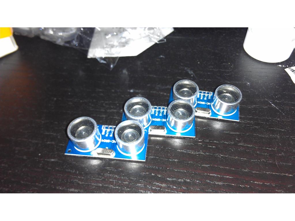
cE9s4PsOgeBQIORwjd5!~~60_1-634818020230156250.jpg)


BO)Lupuc4g~~60_35-634706297915000000.jpg)
LupbT6!~~60_35-634706298769375000.jpg)


C5j!~~60_35-634655044863125000.jpg)


C5j!~~60_35-634659603510781250.jpg)


C5j!~~60_35-634651704046230469.jpg)
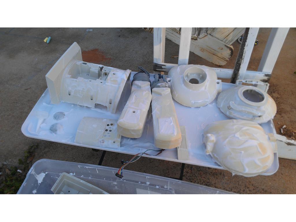
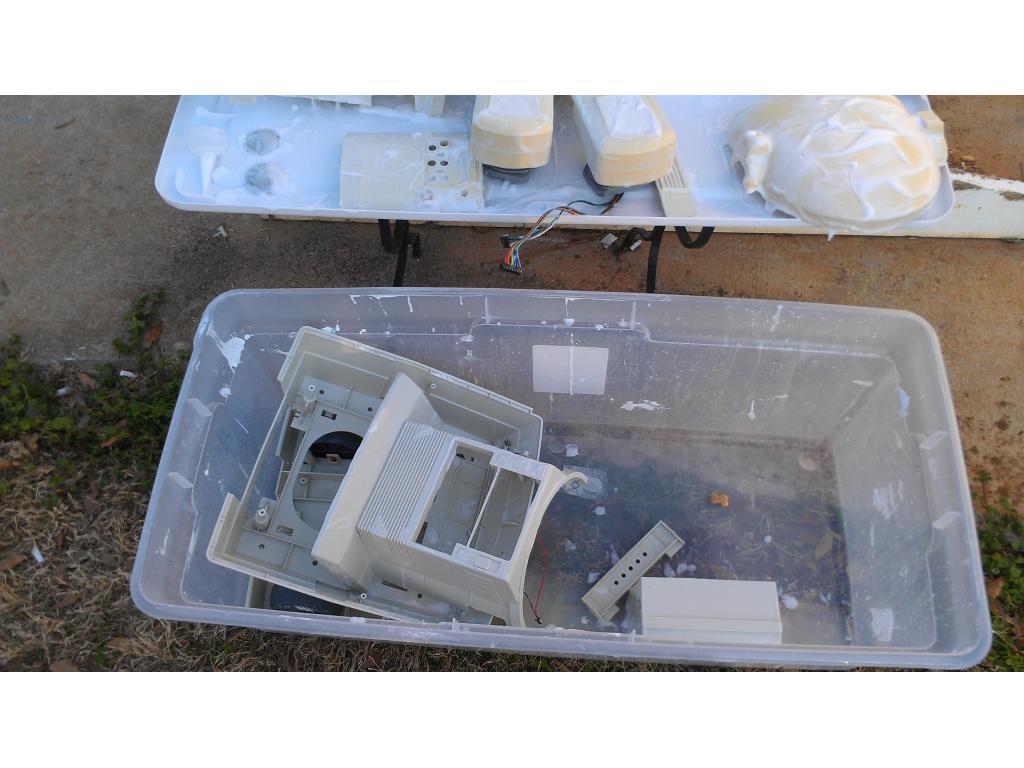
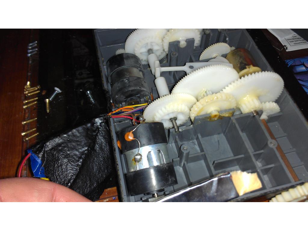
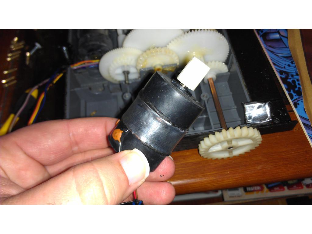
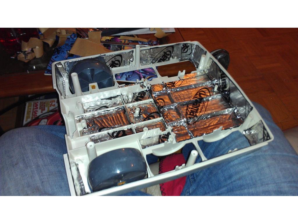
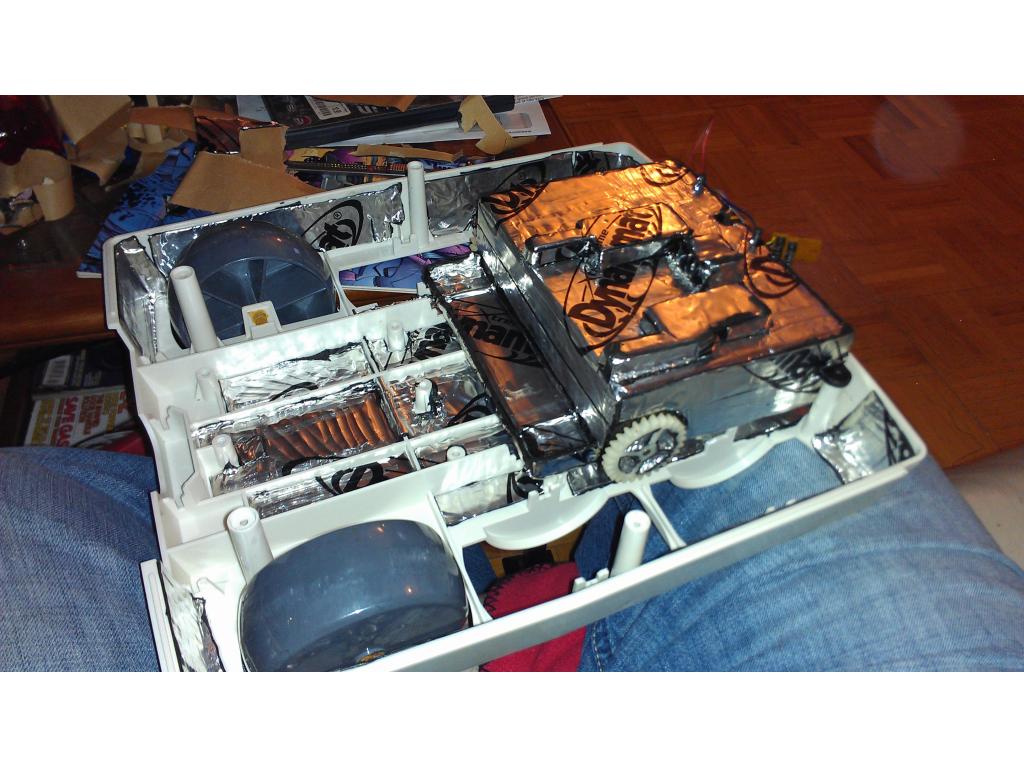
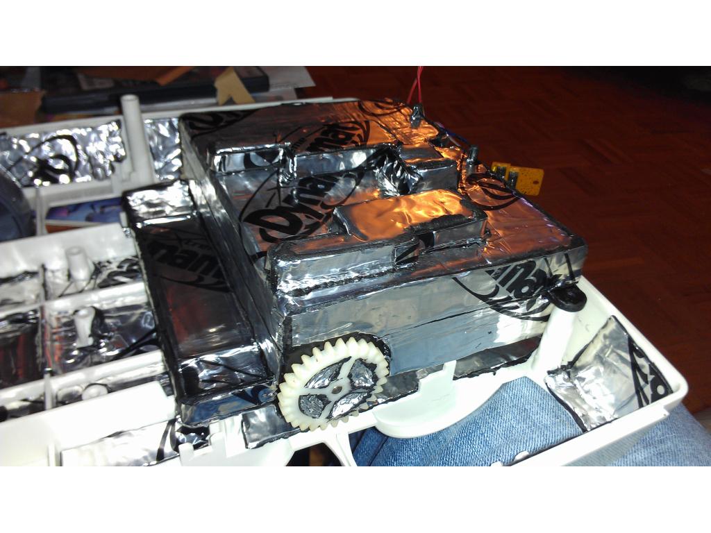


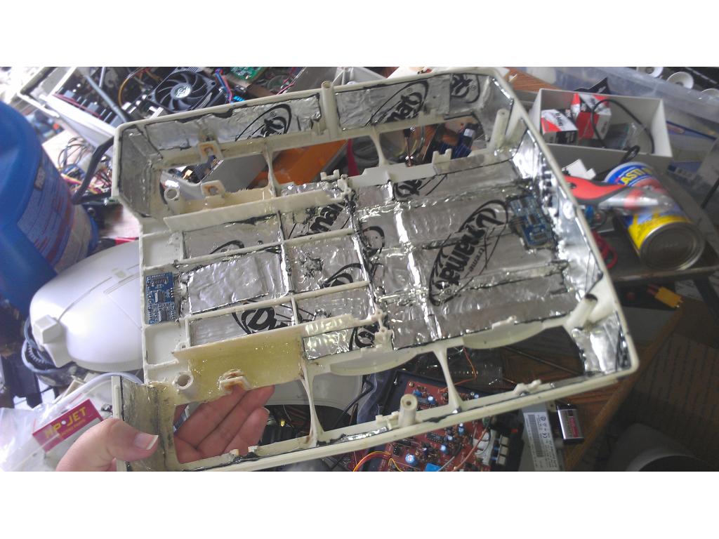
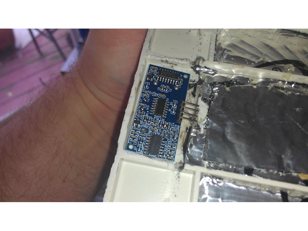
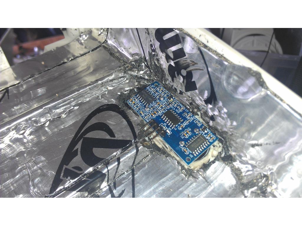


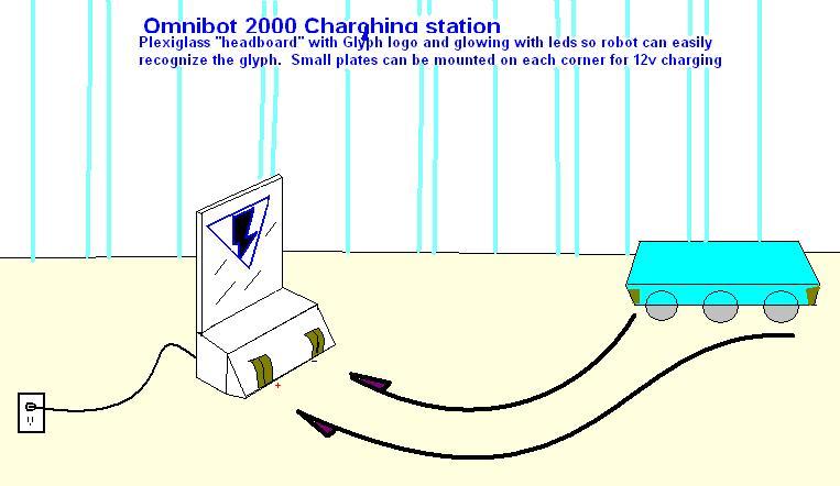
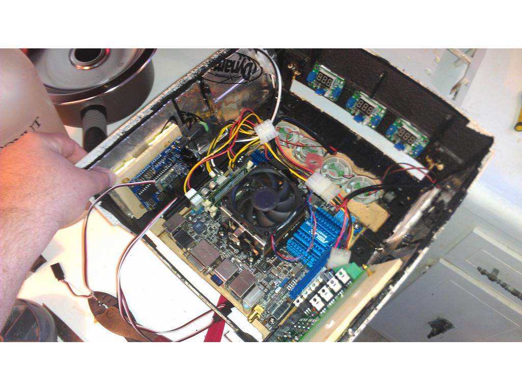
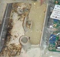
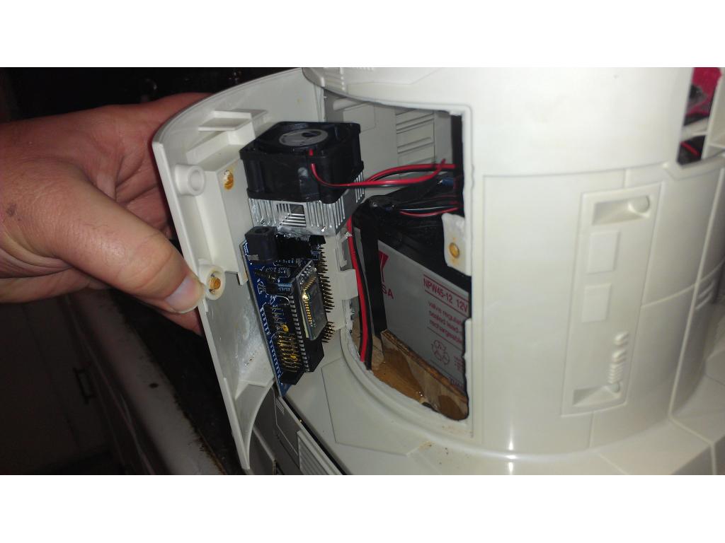
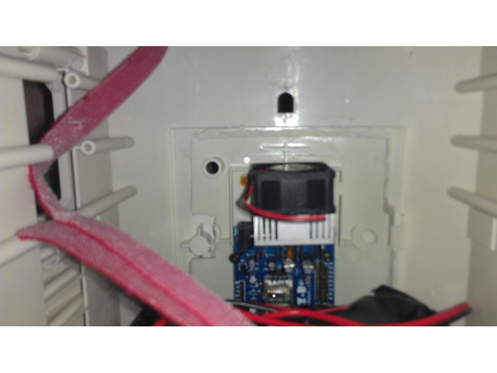


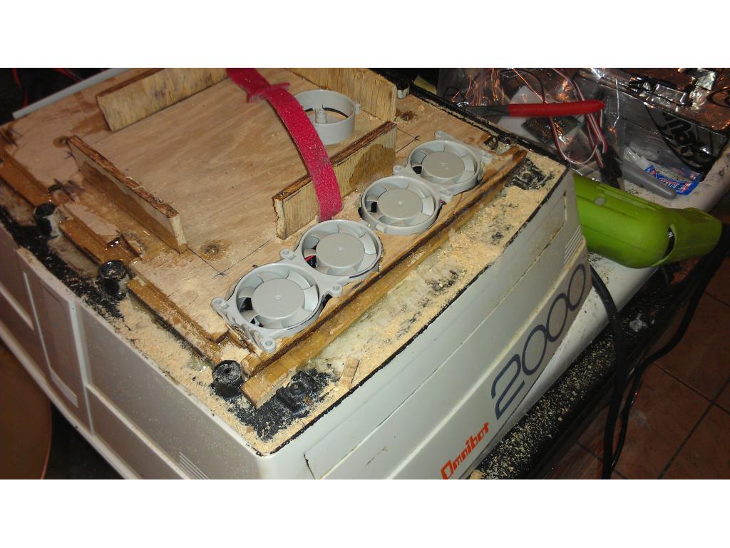
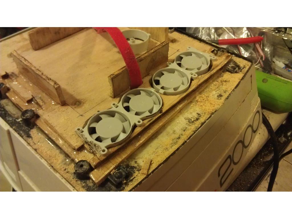
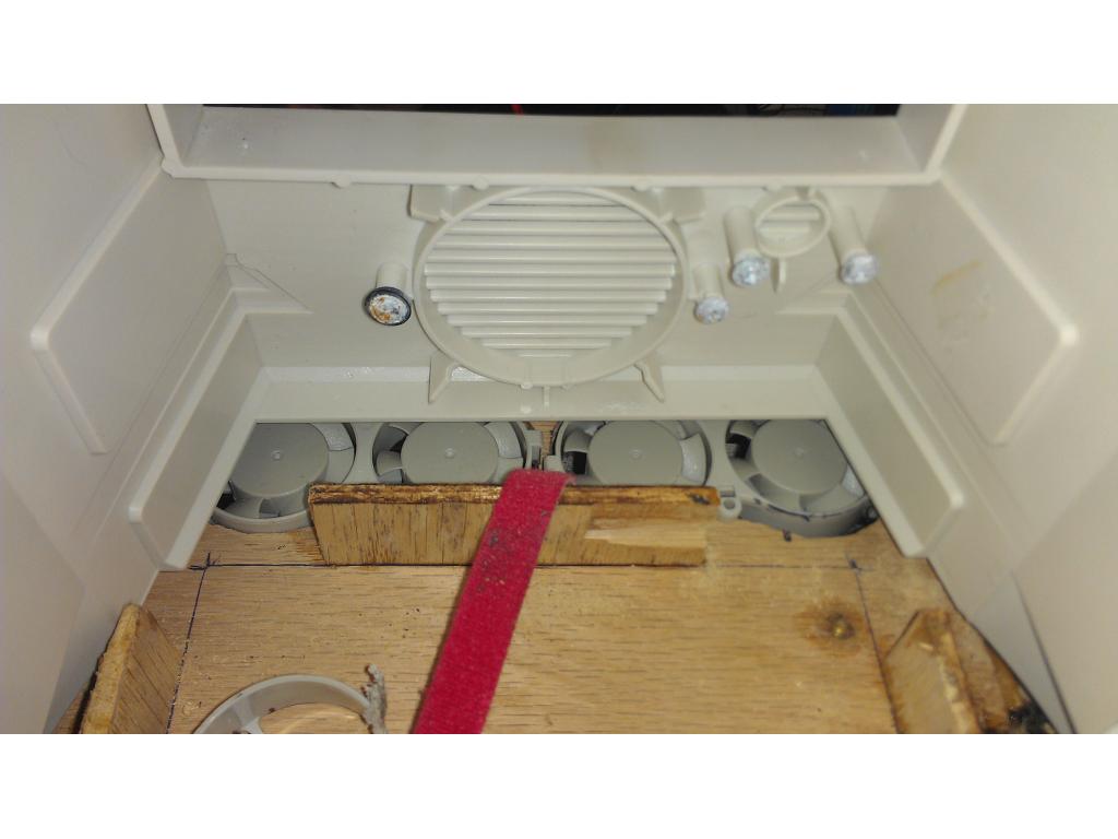

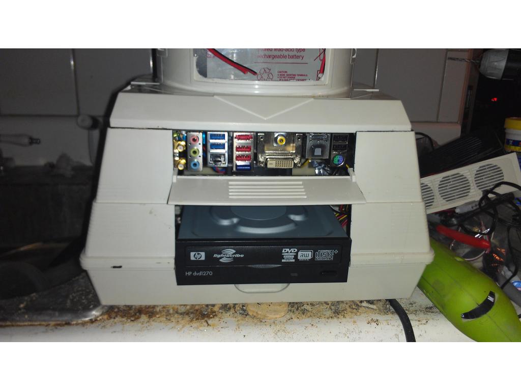


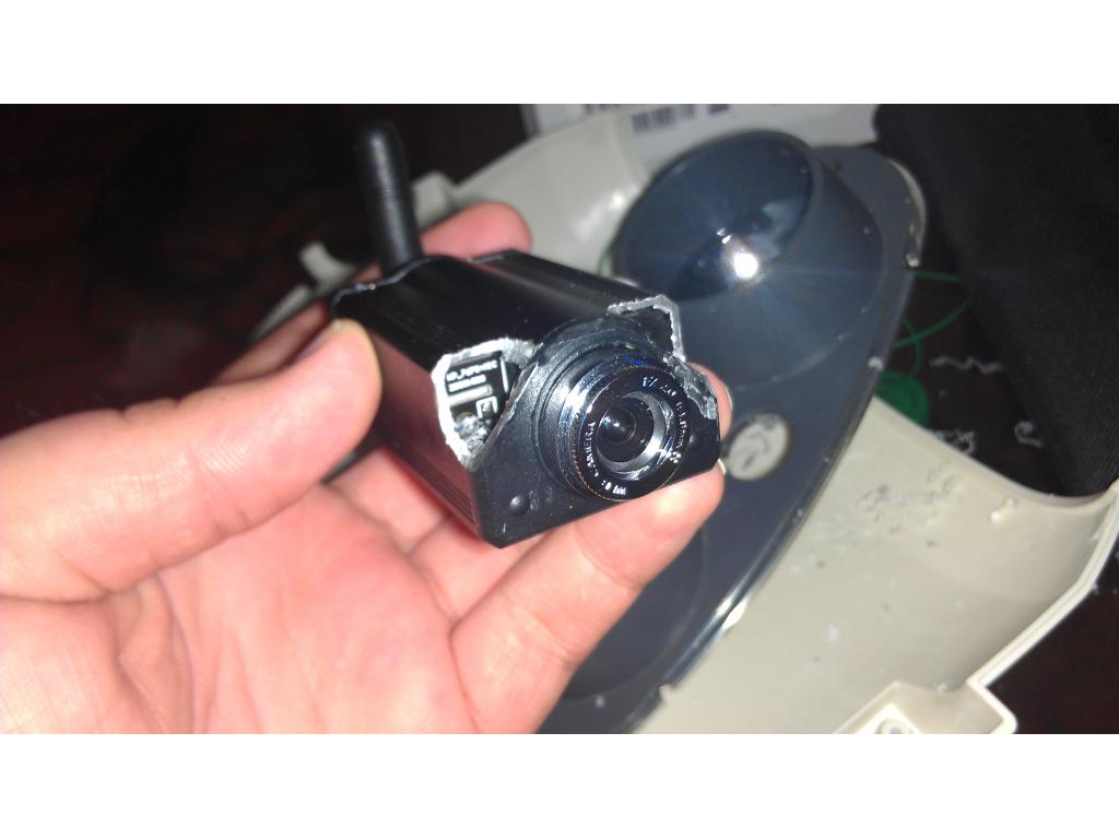
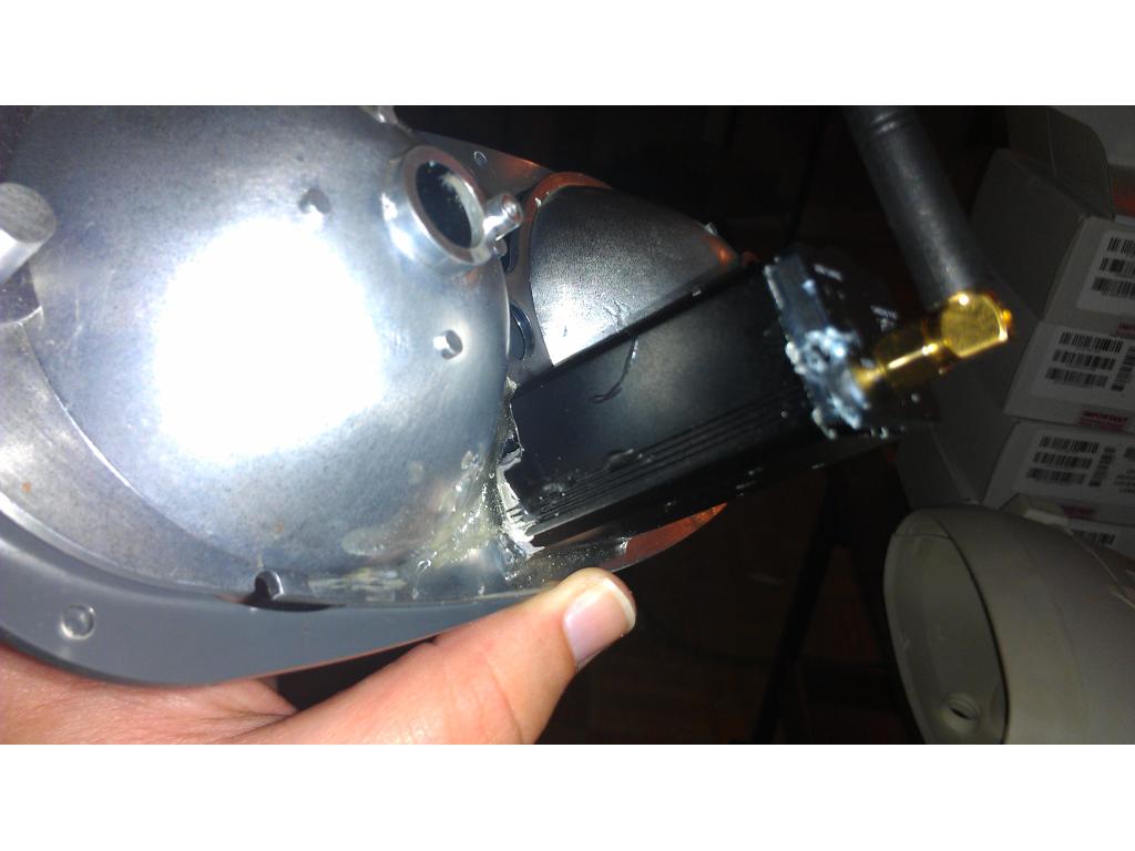
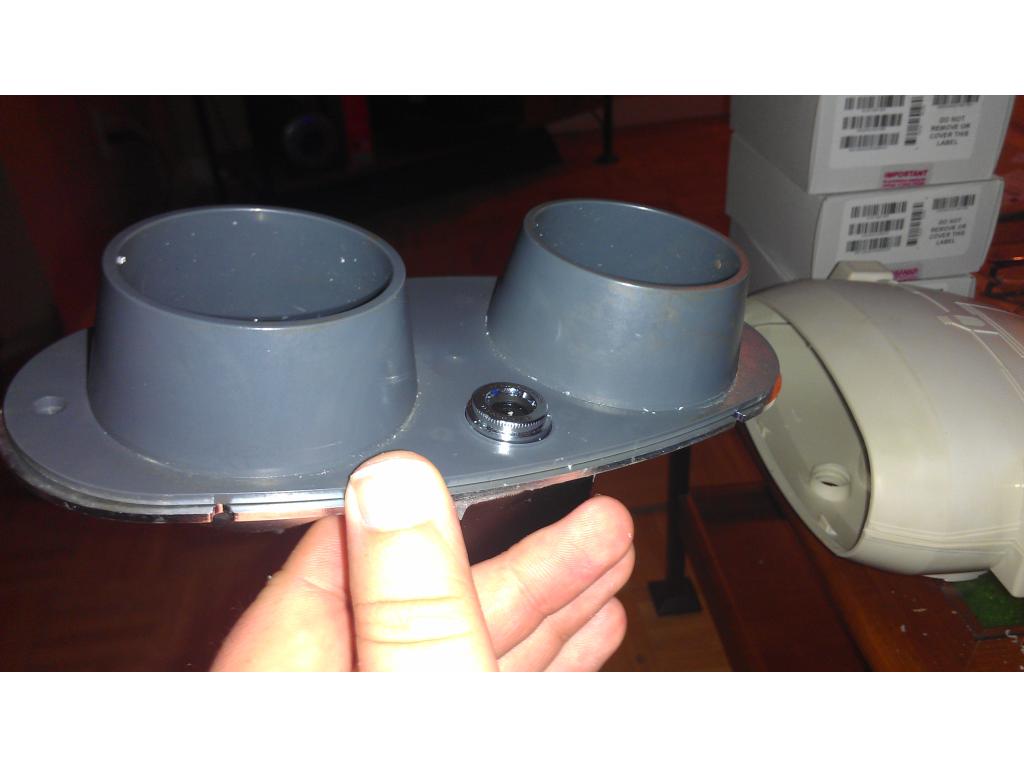
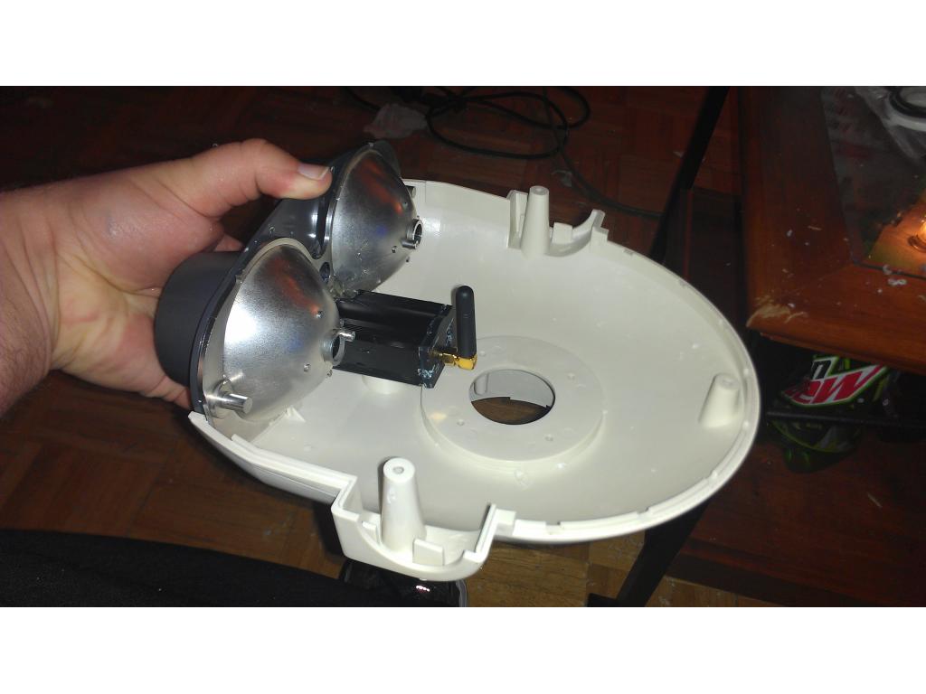

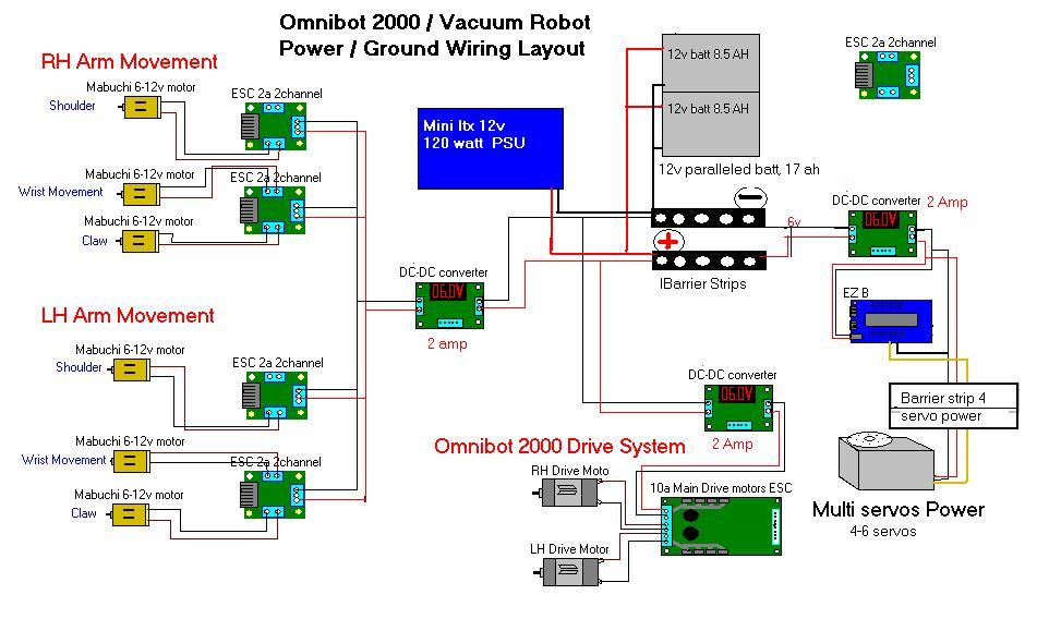

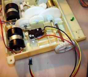
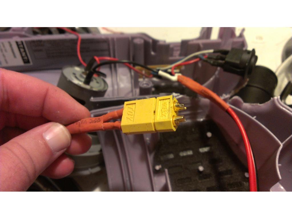
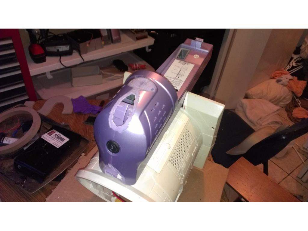
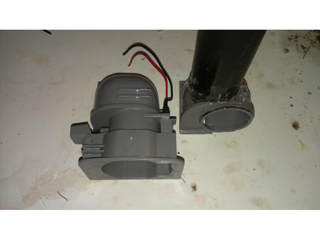

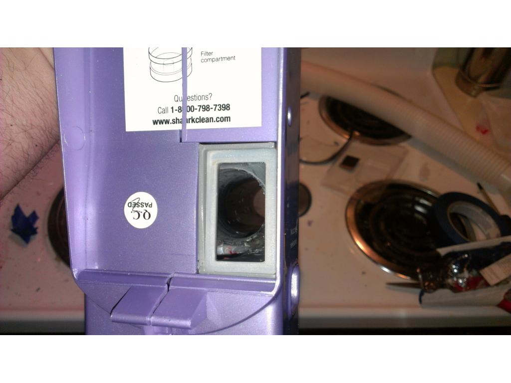
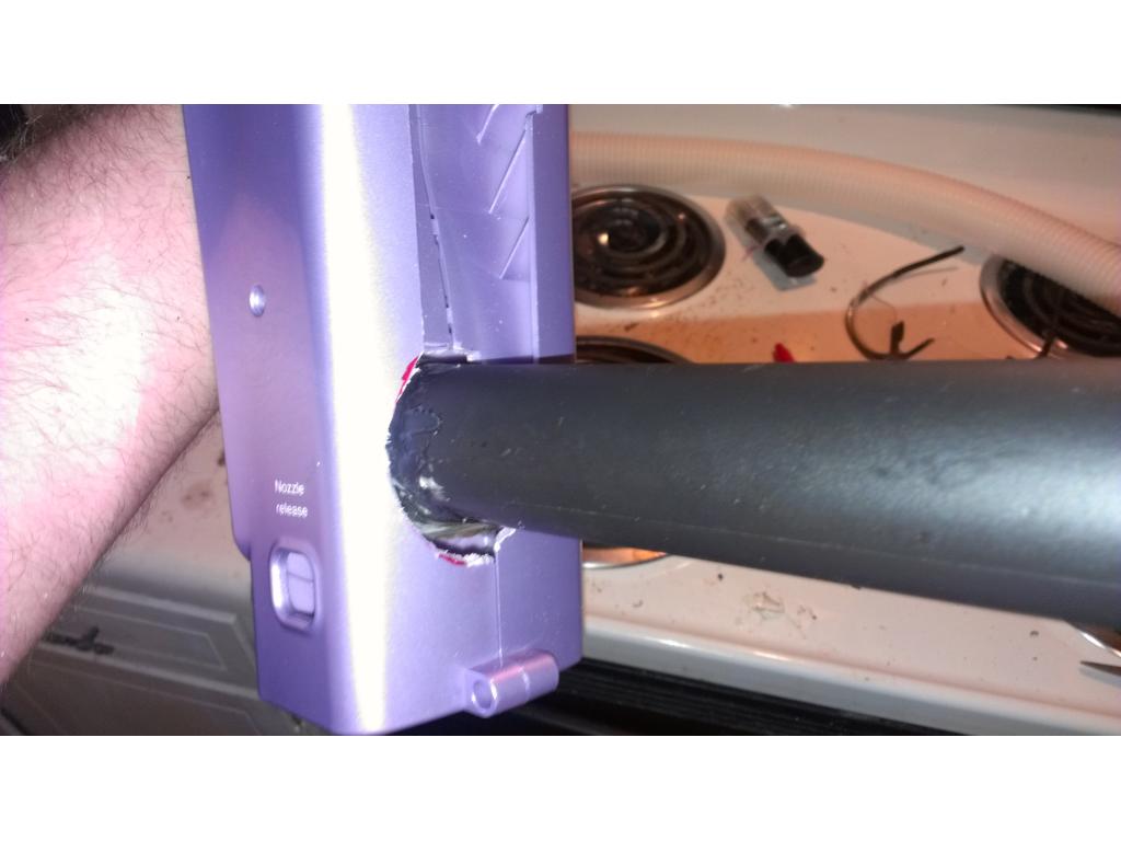
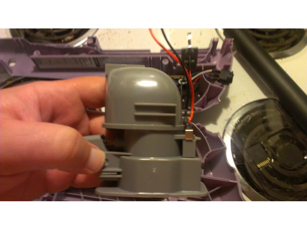
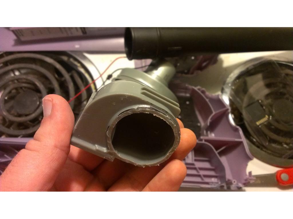
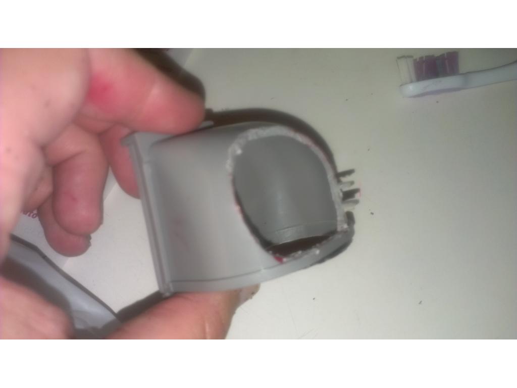
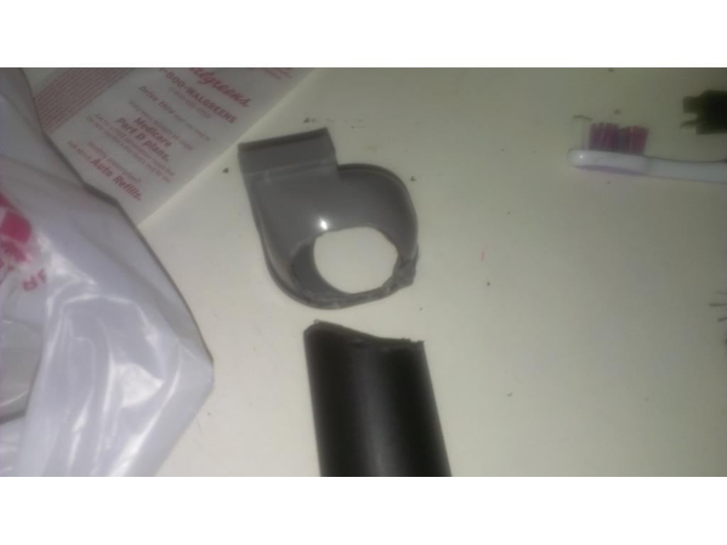
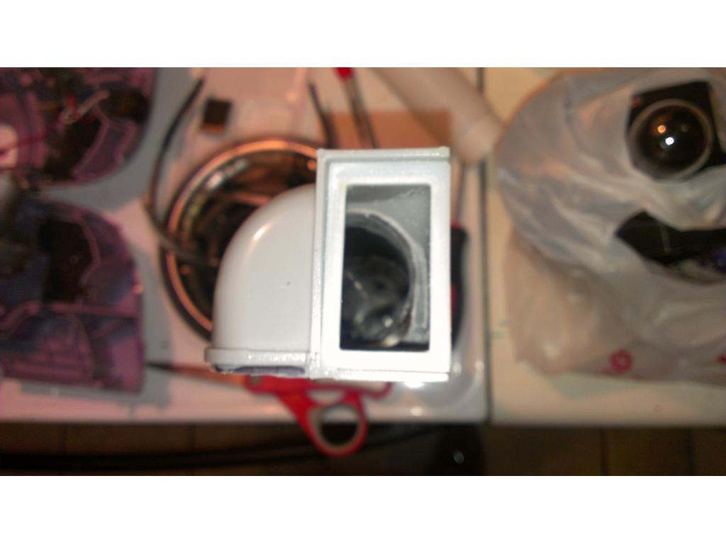
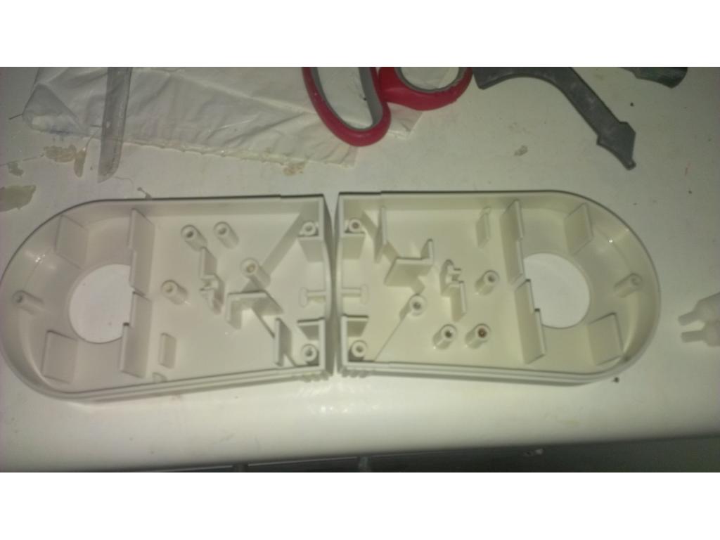
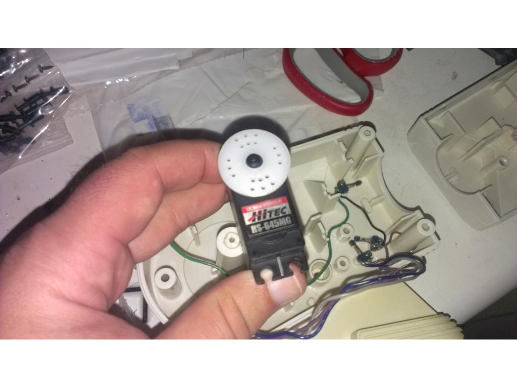

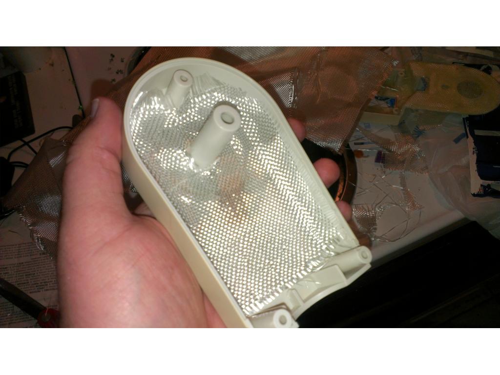
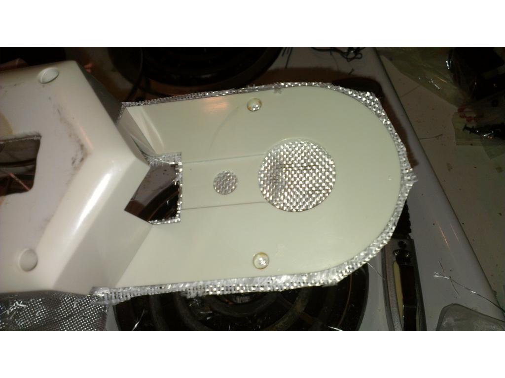
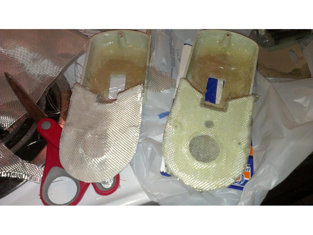

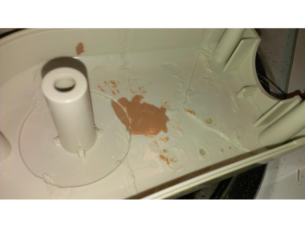
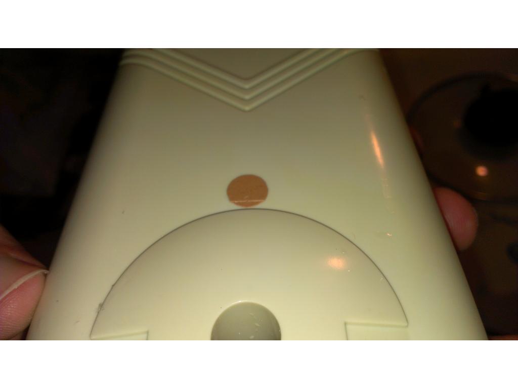

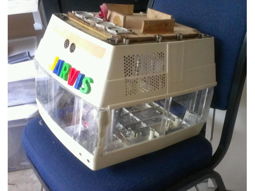
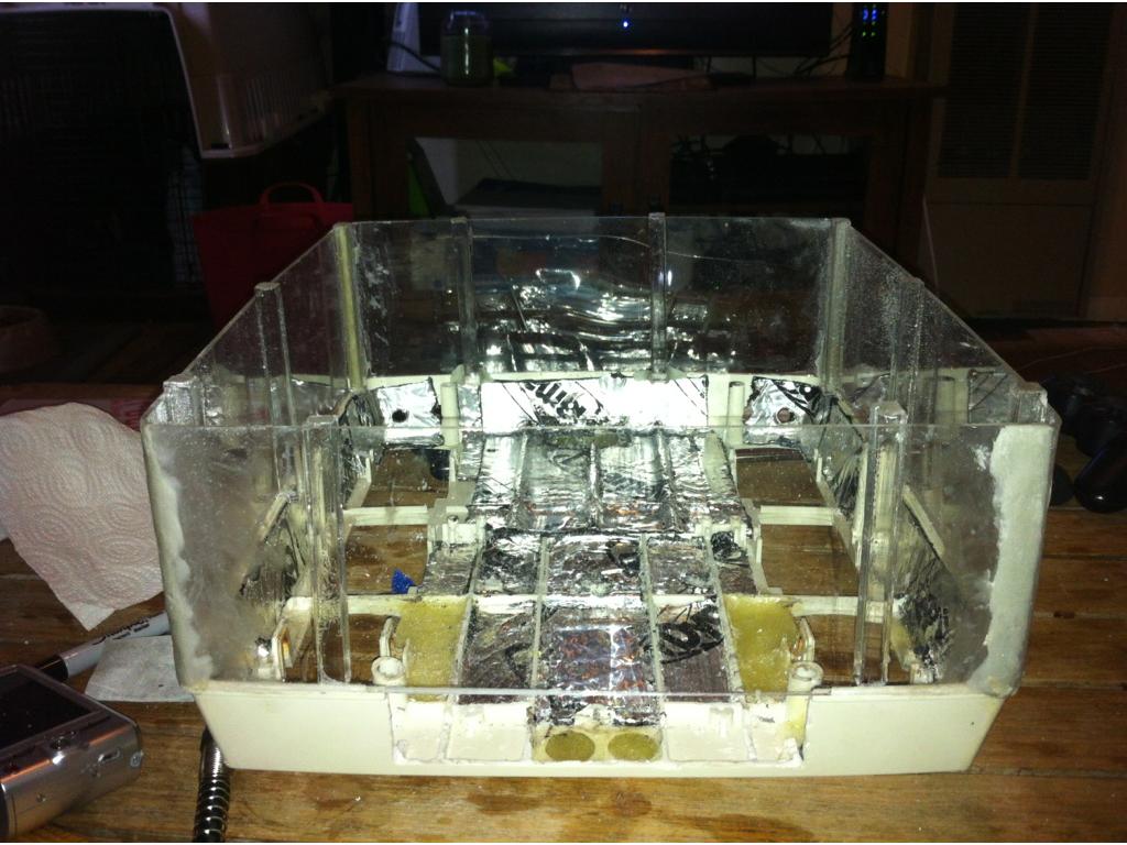
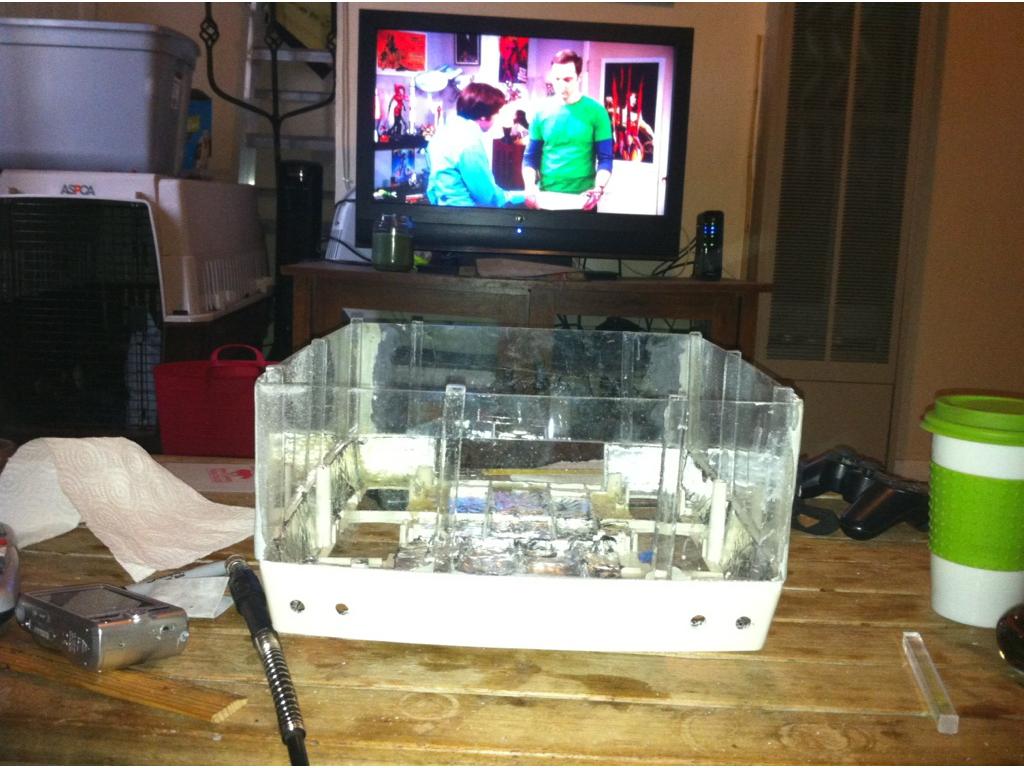
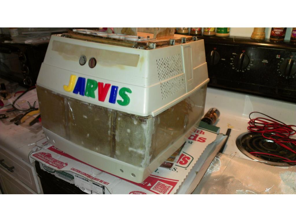
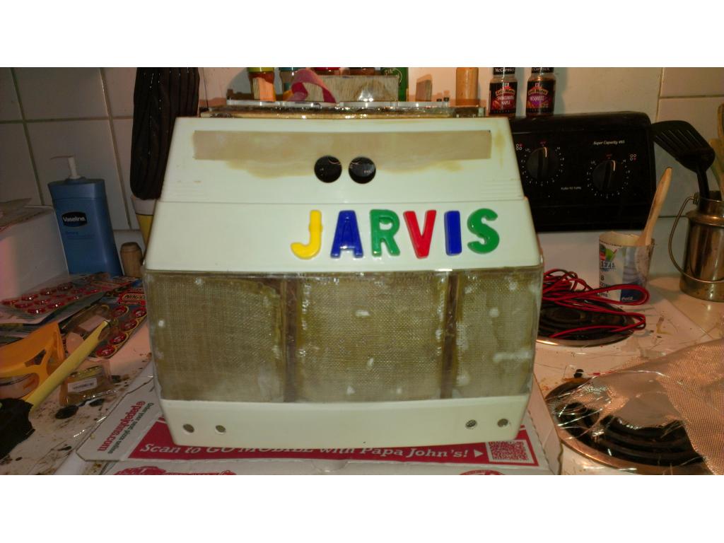


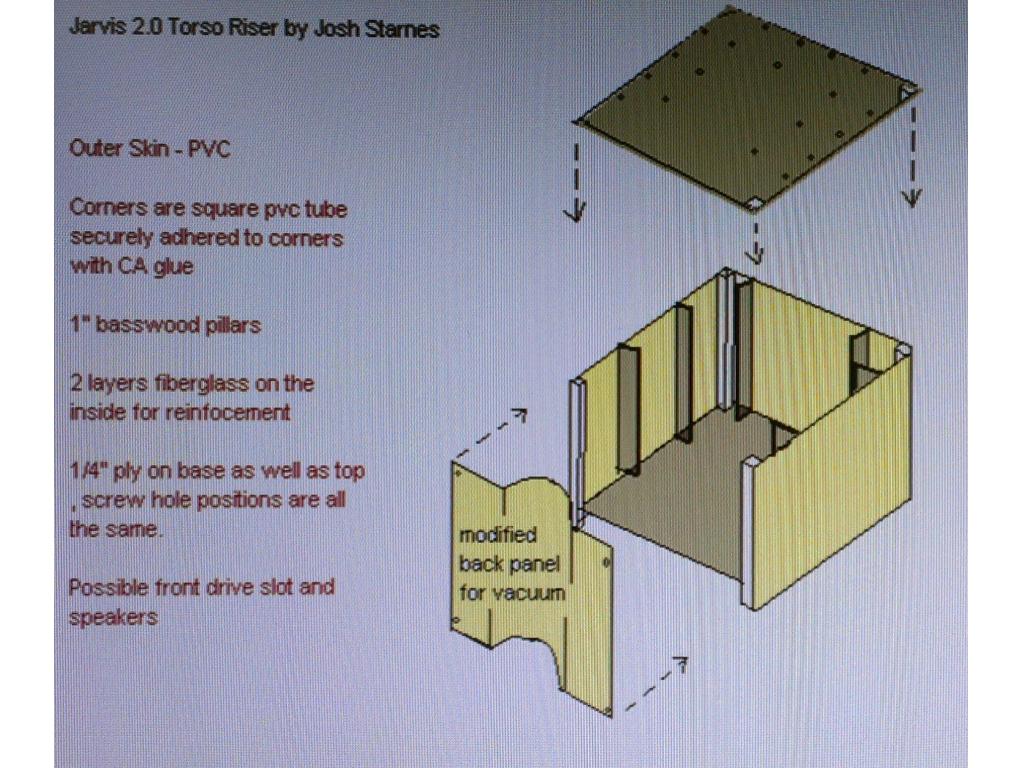
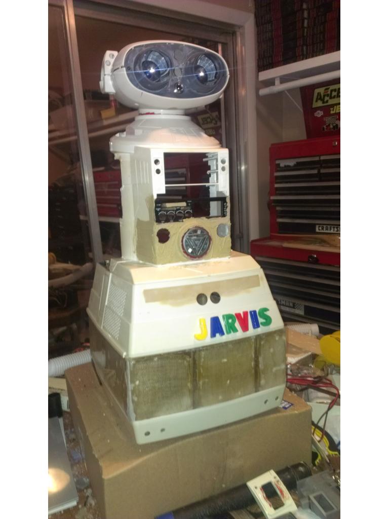
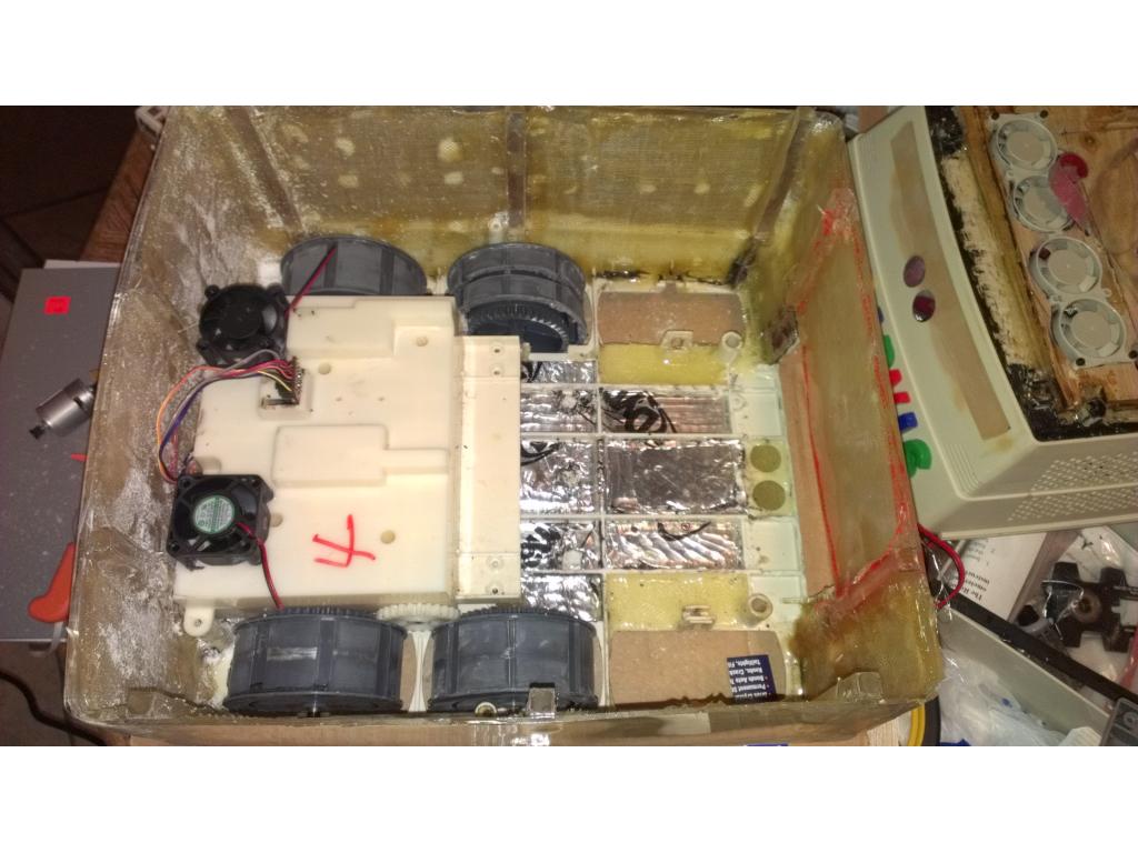
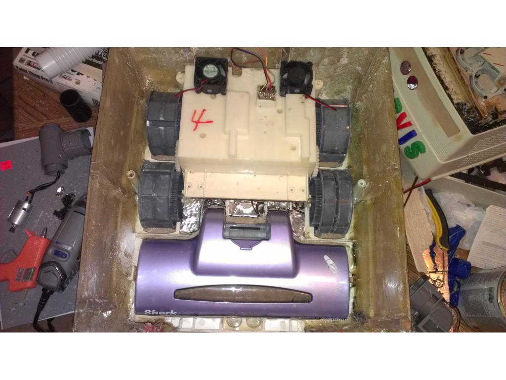
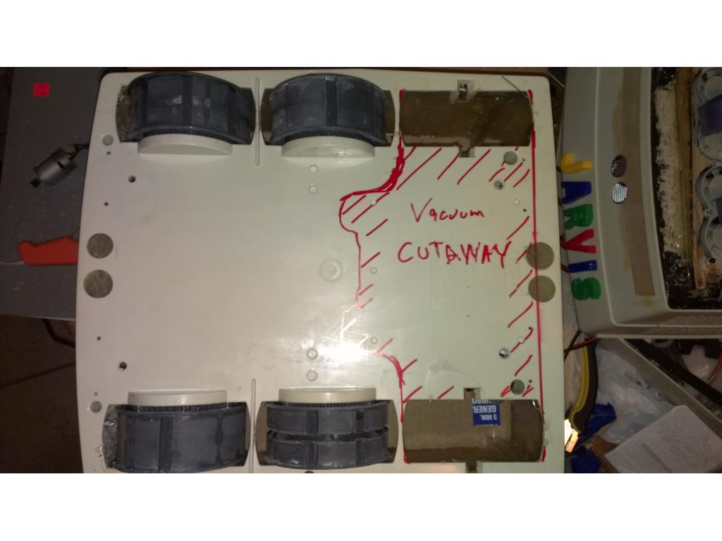
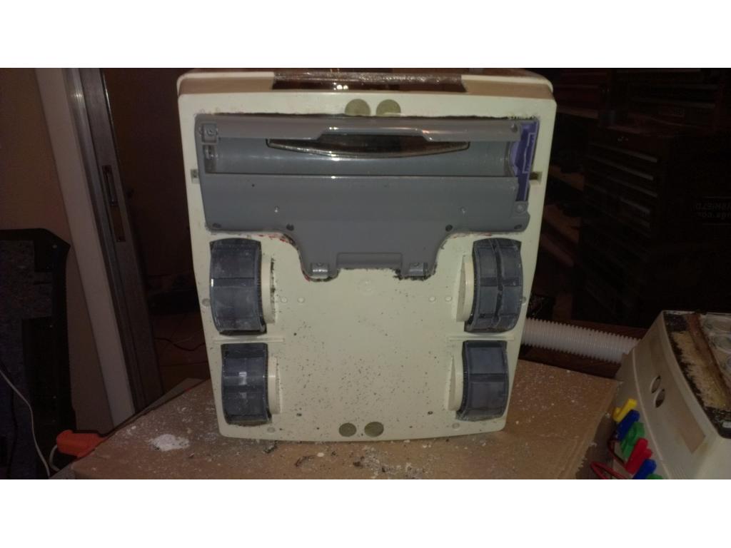
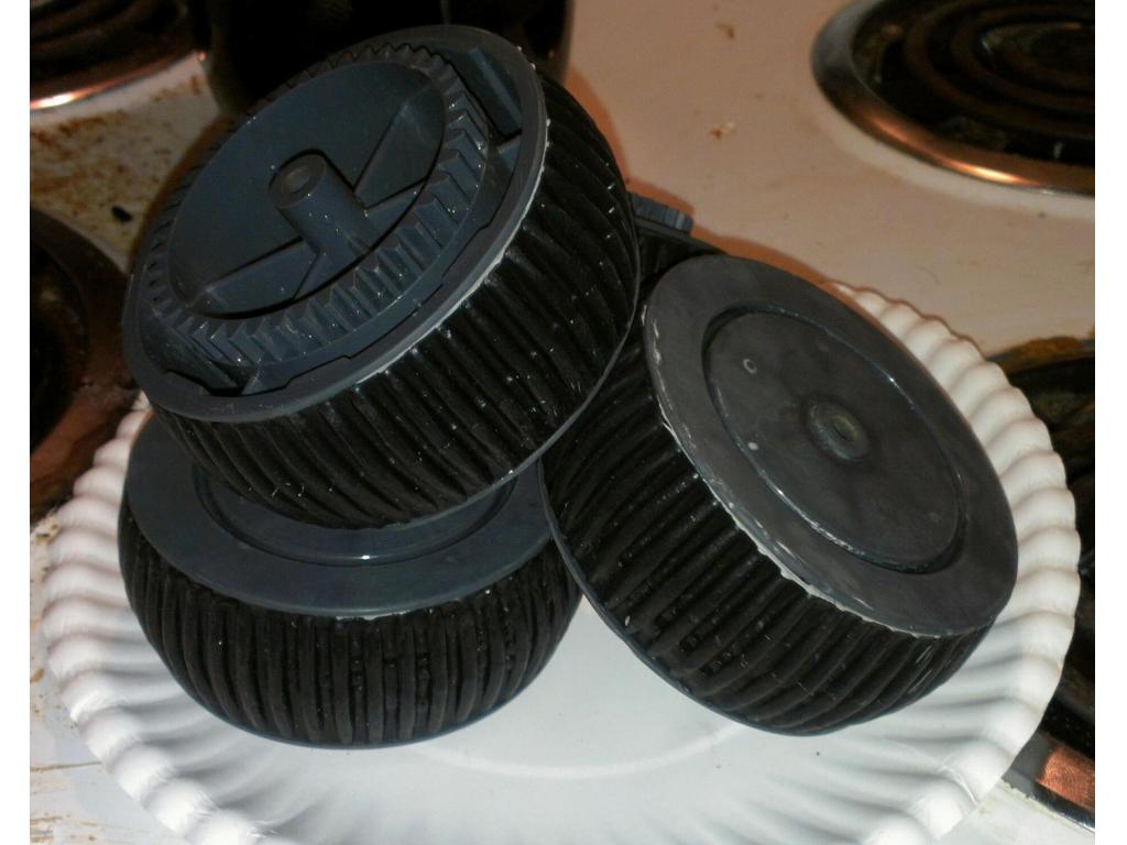
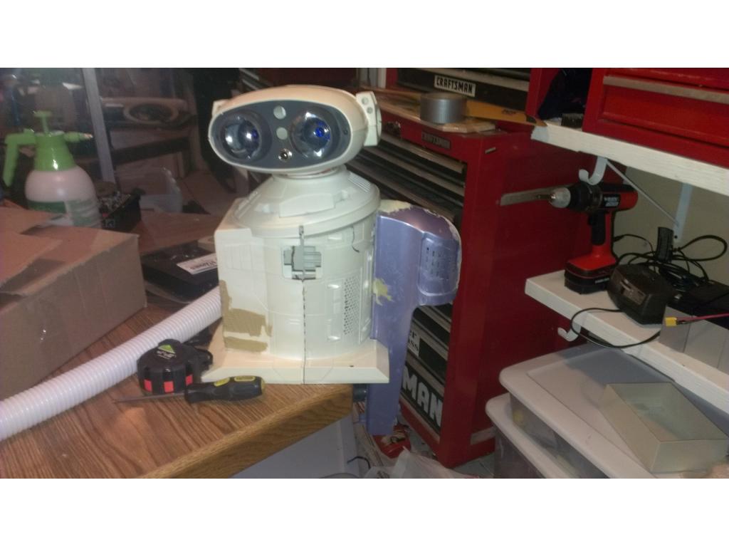
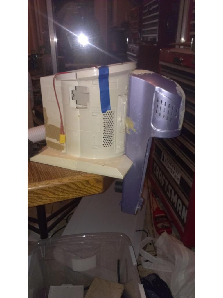

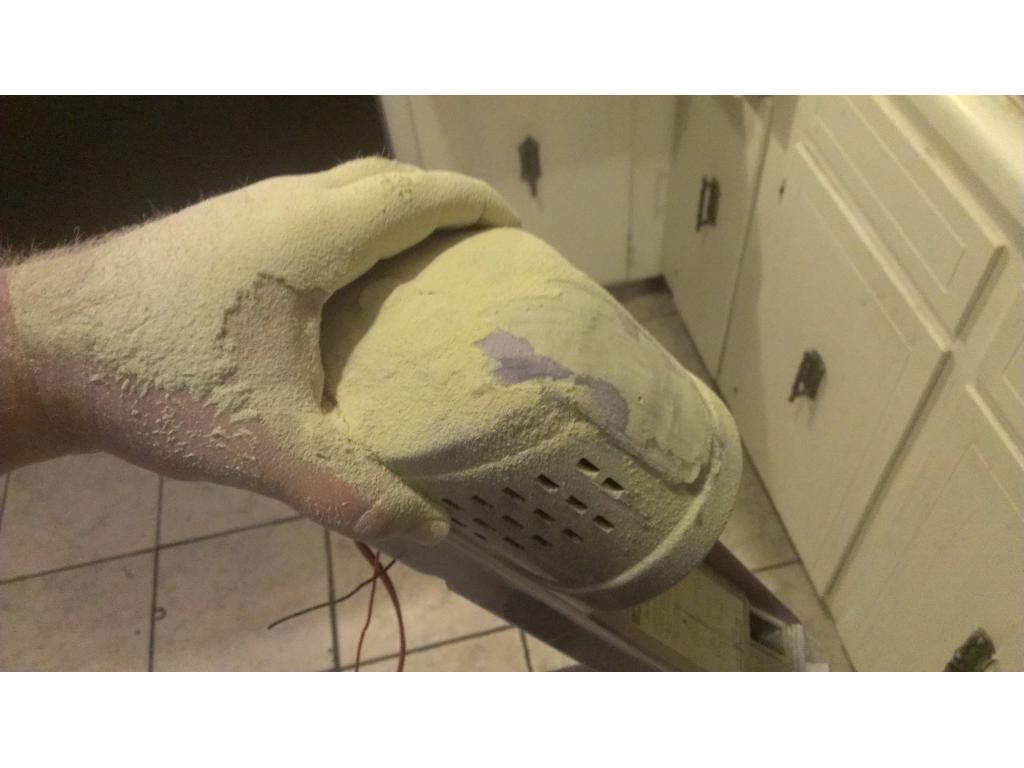

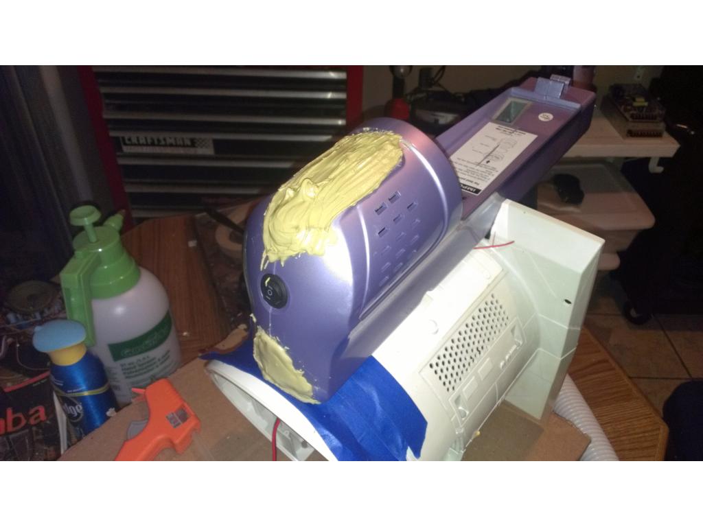
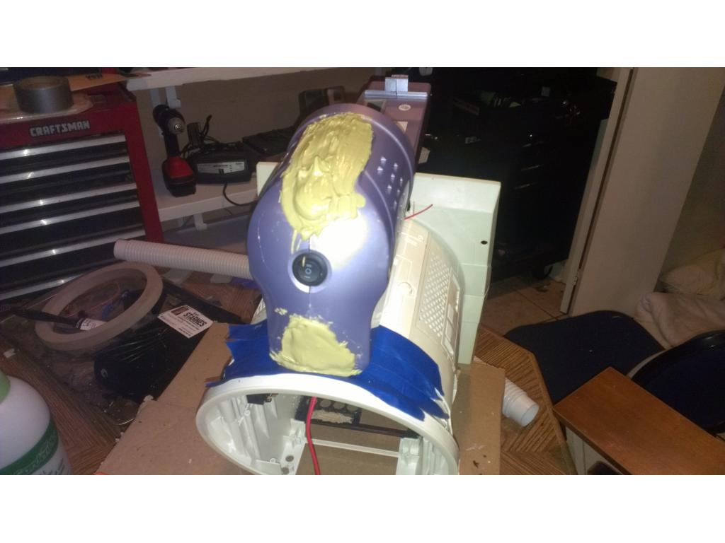

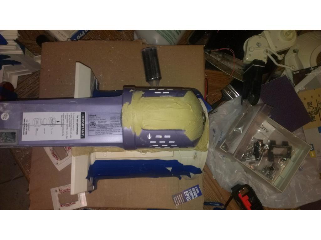
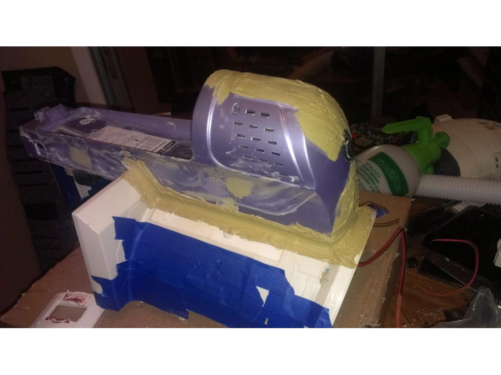
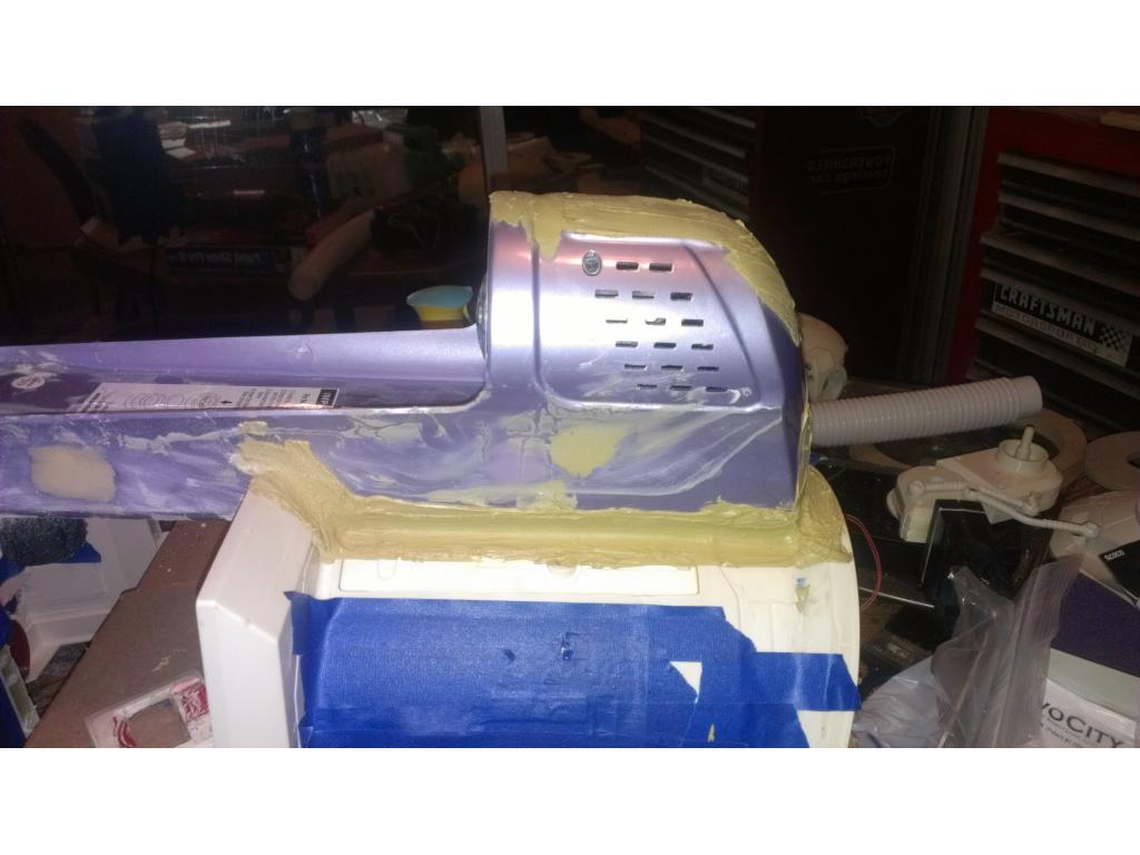
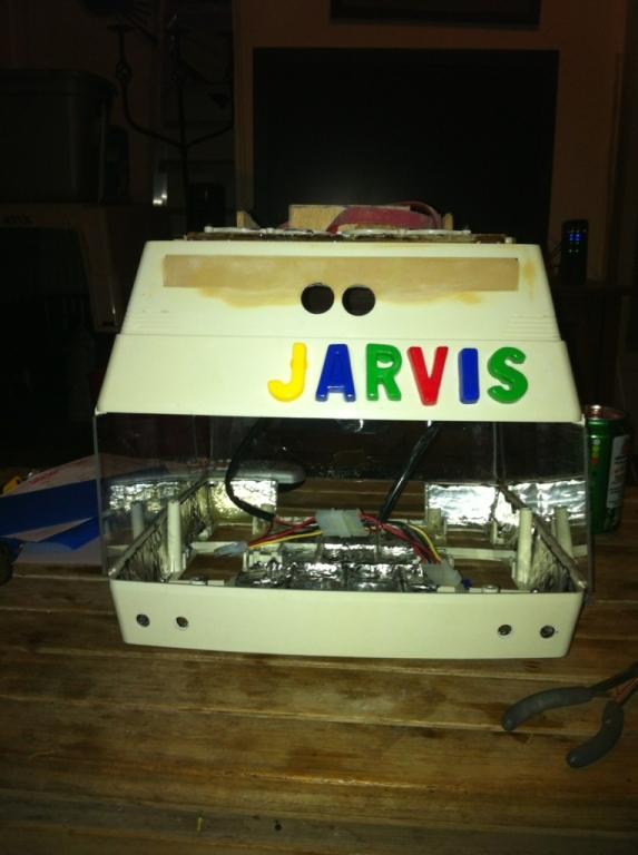
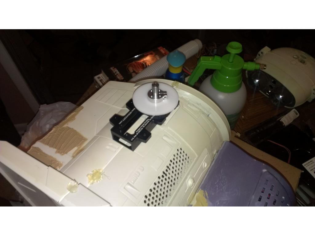
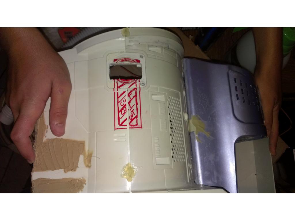
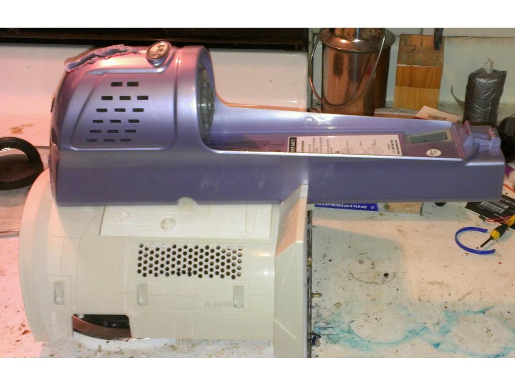
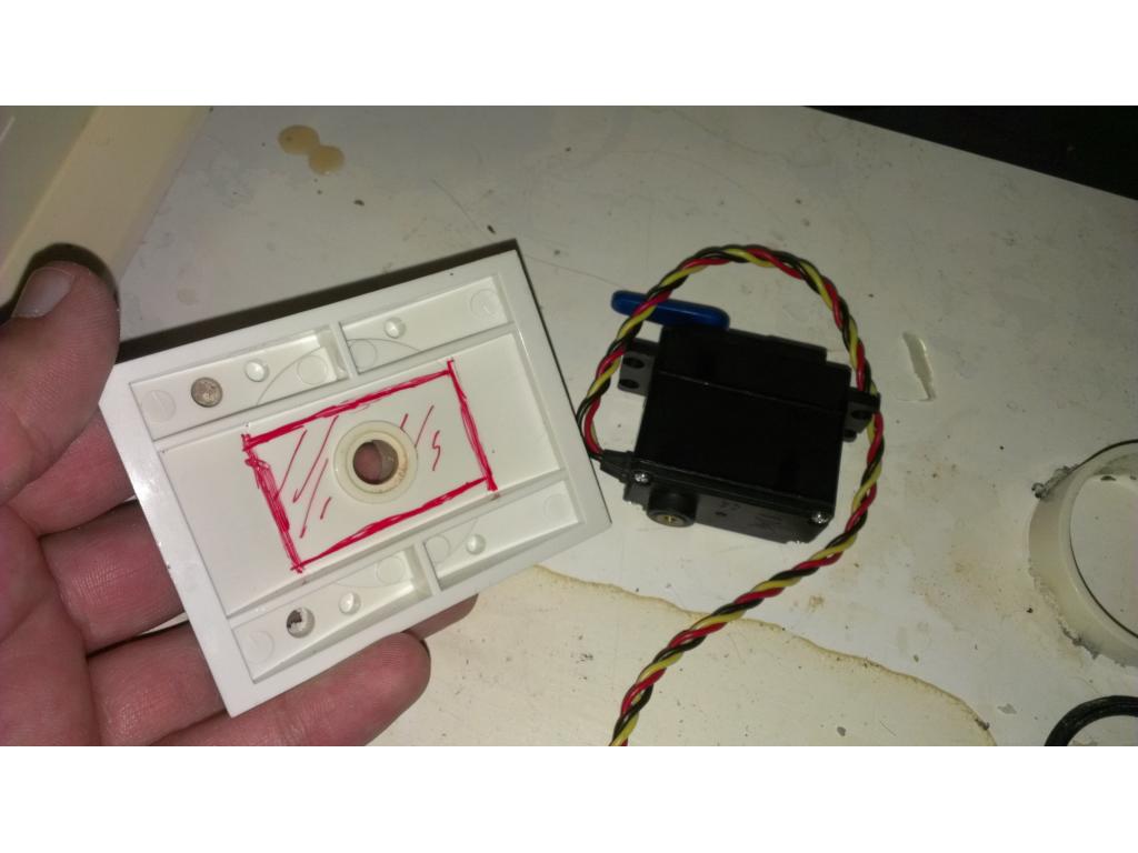
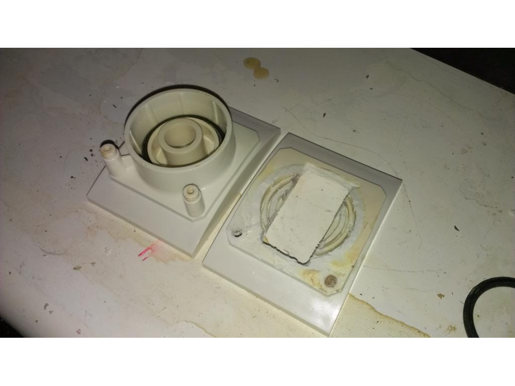
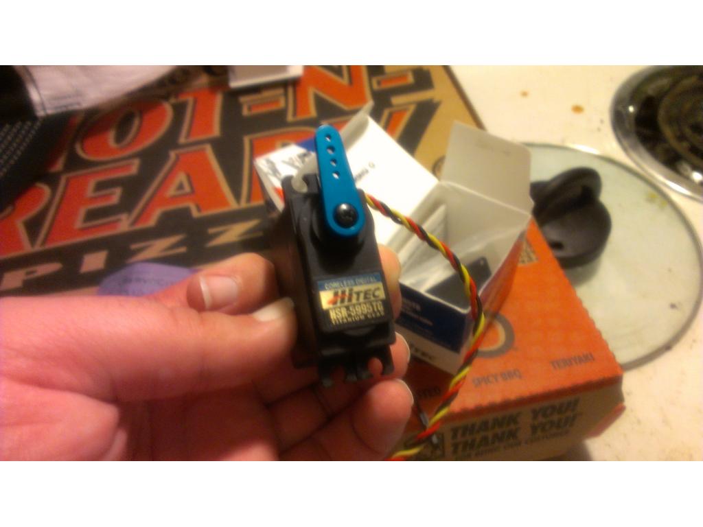

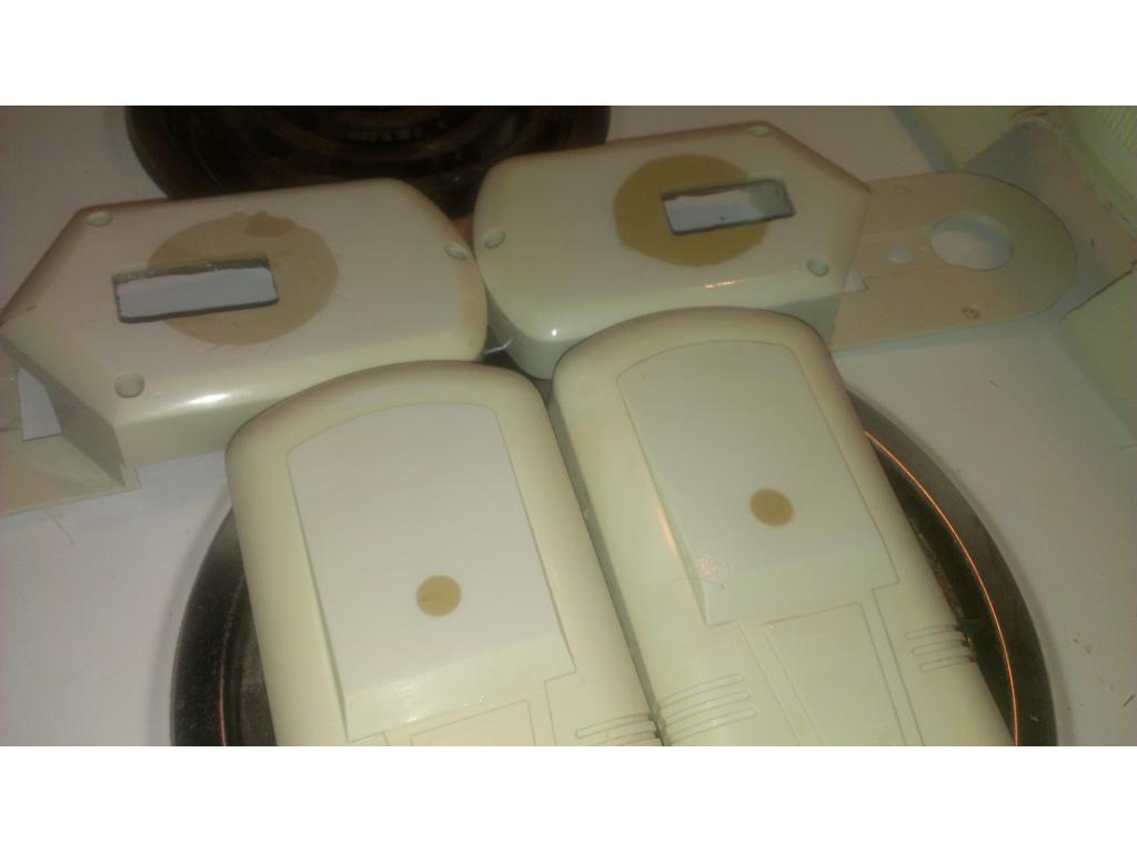
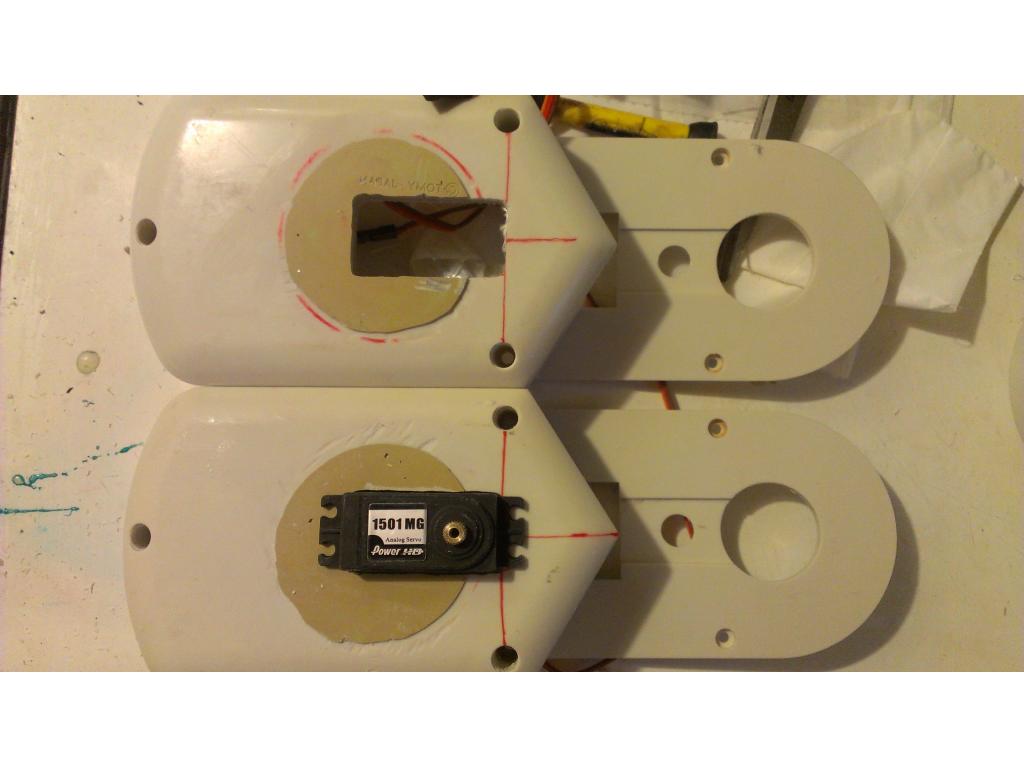
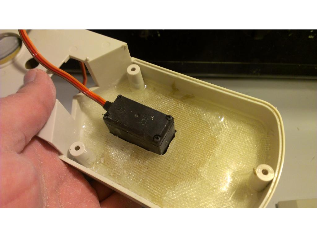

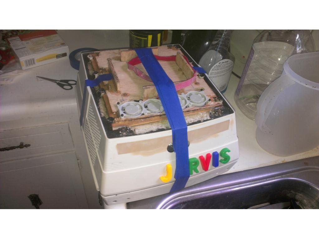
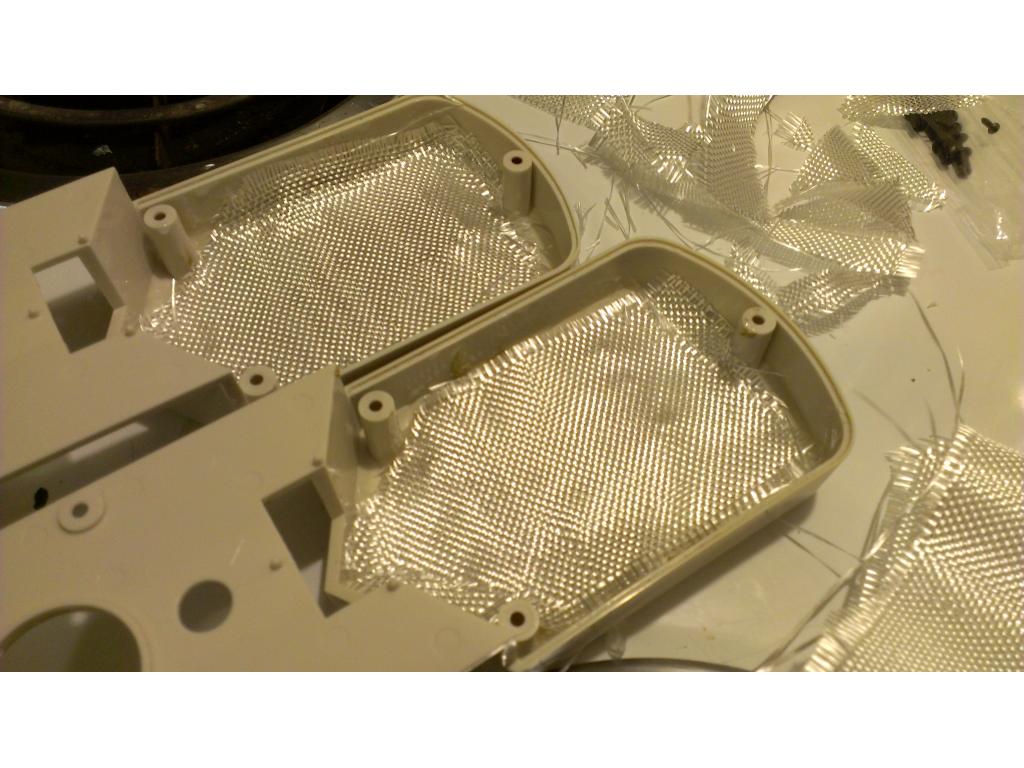
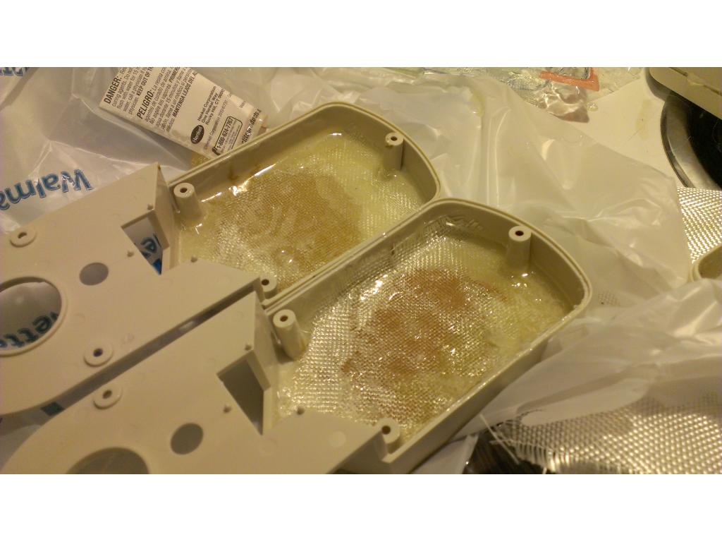
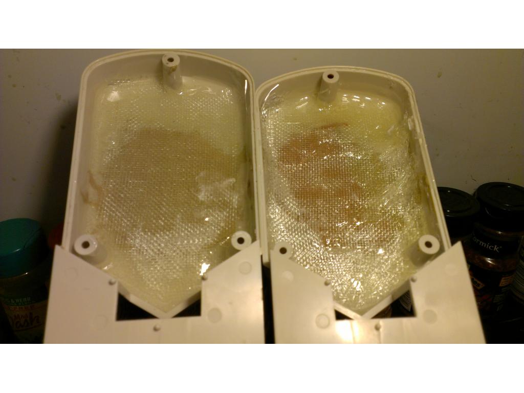
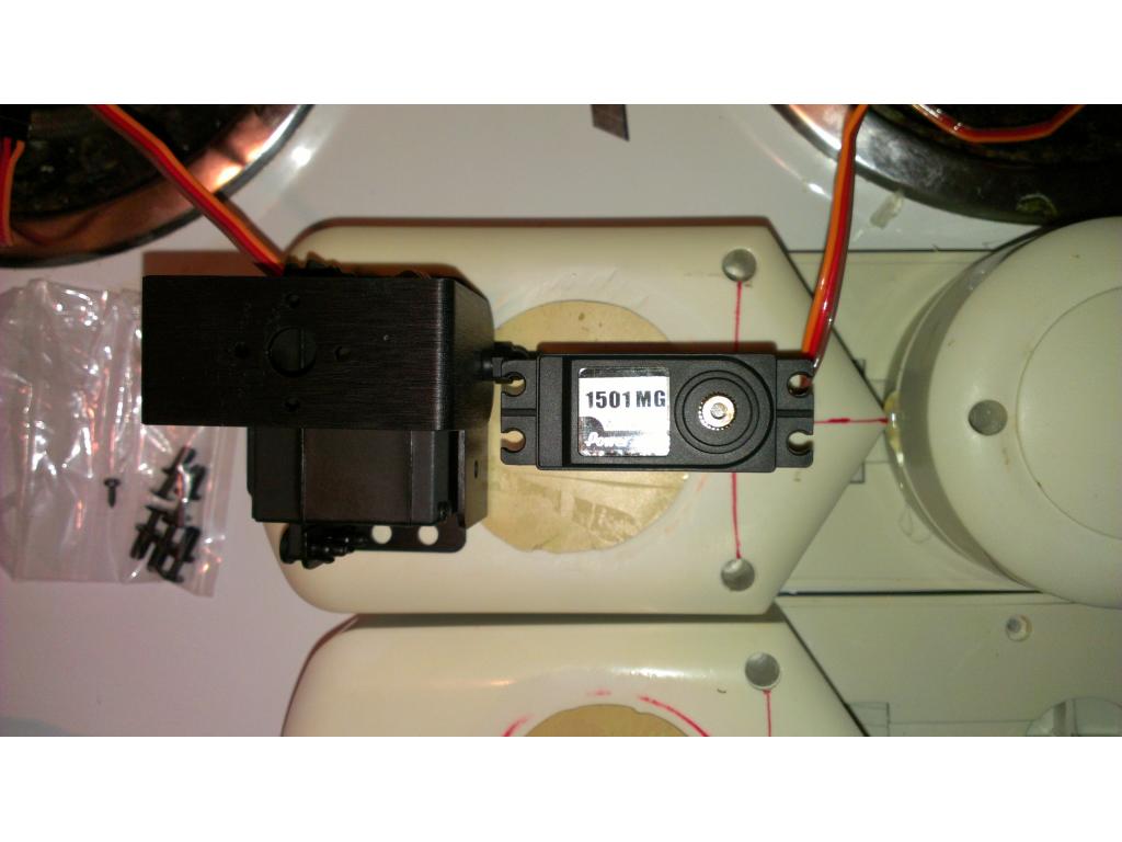
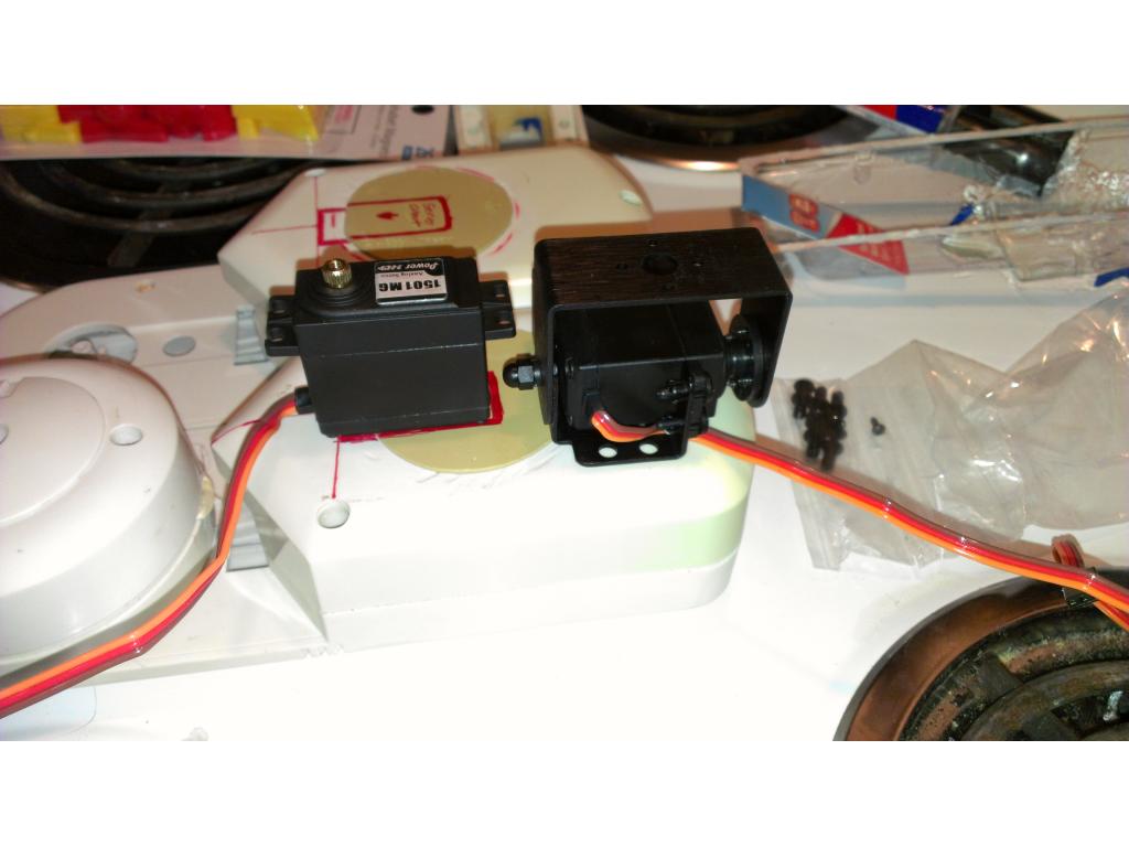
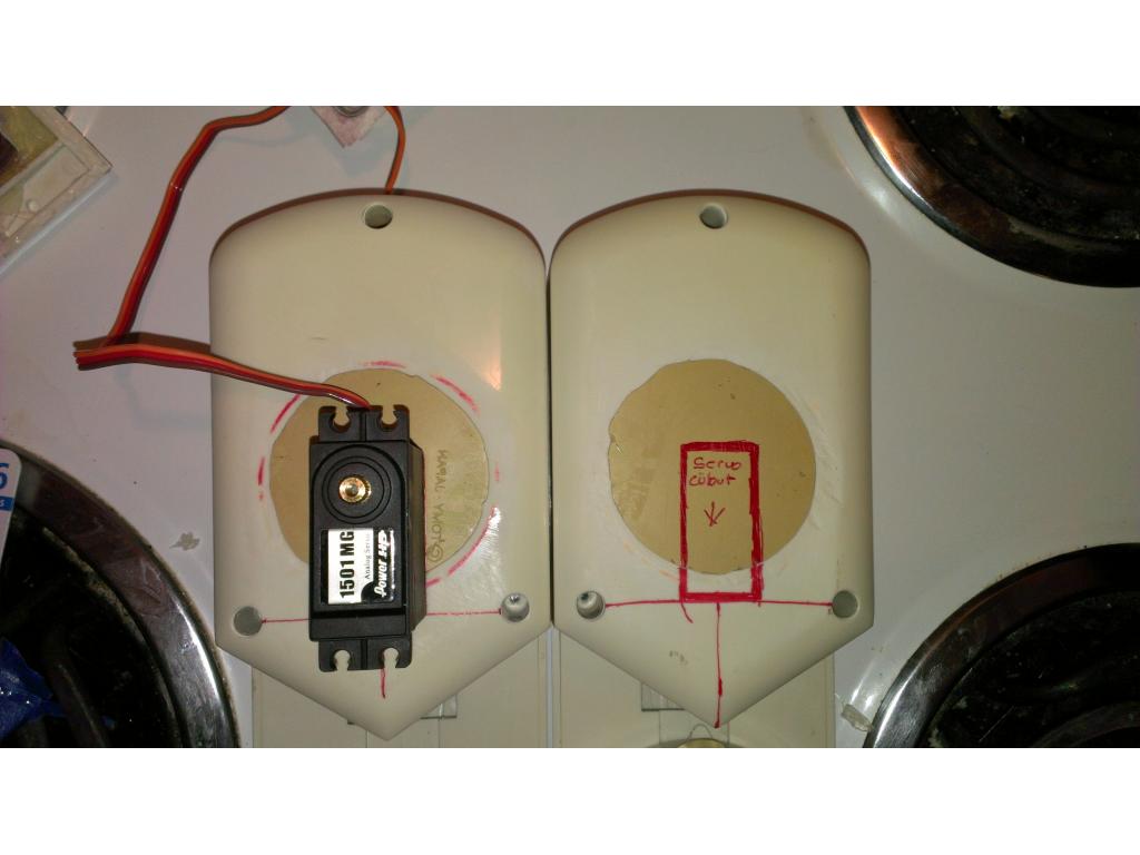
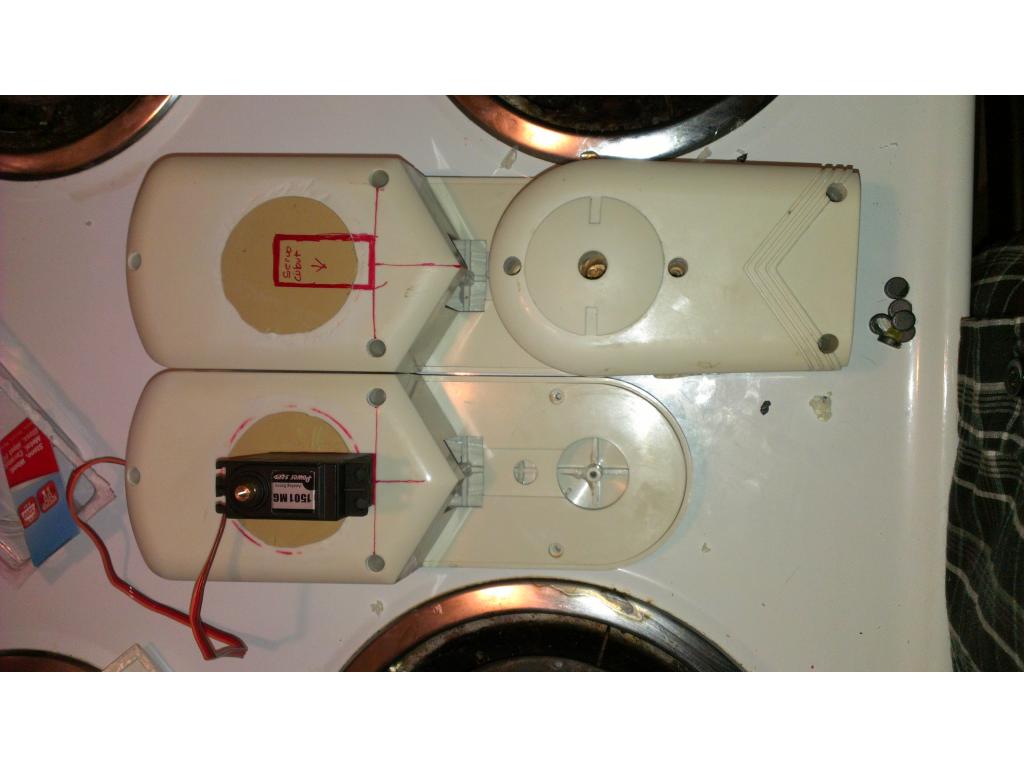
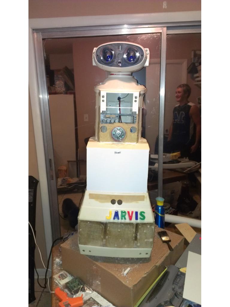

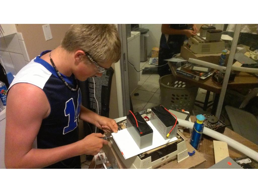
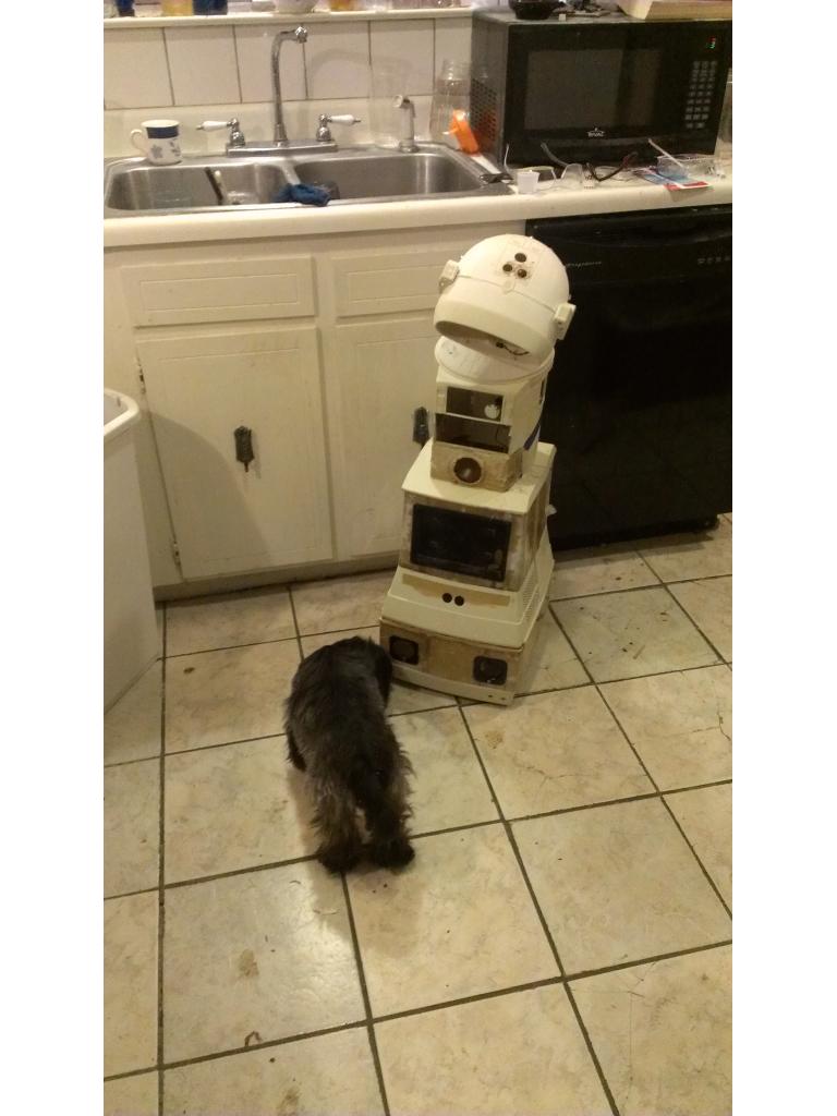
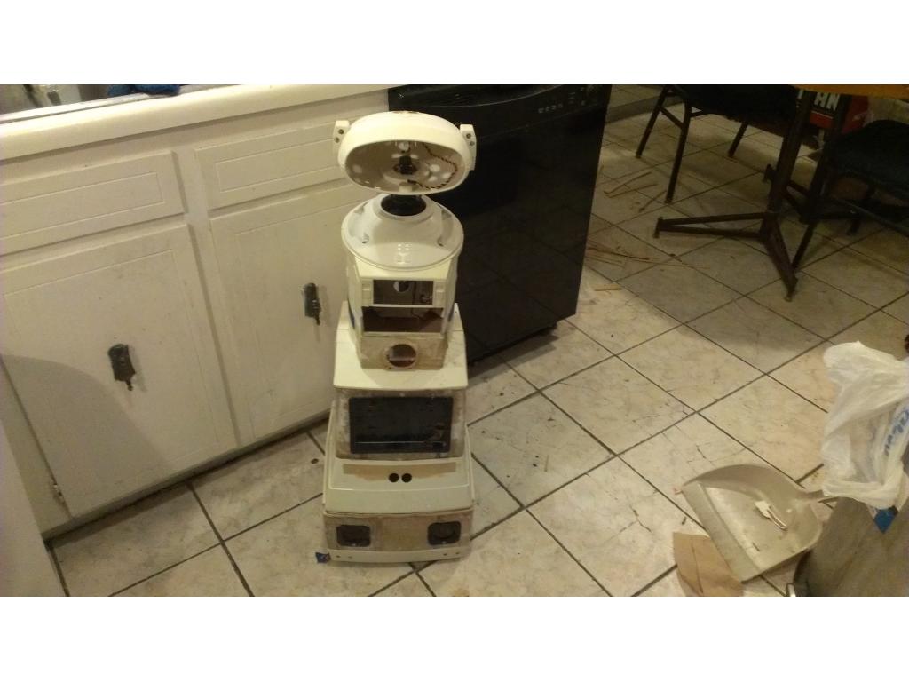
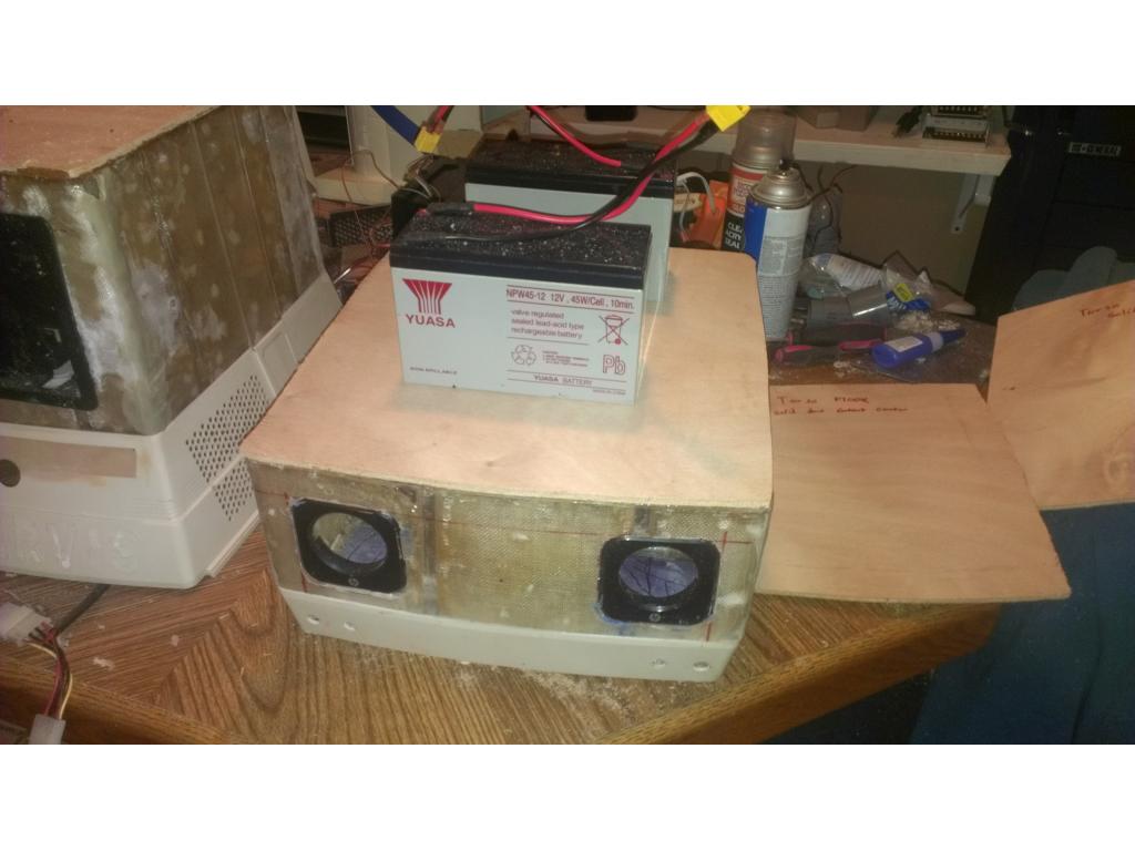

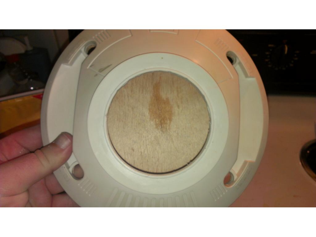
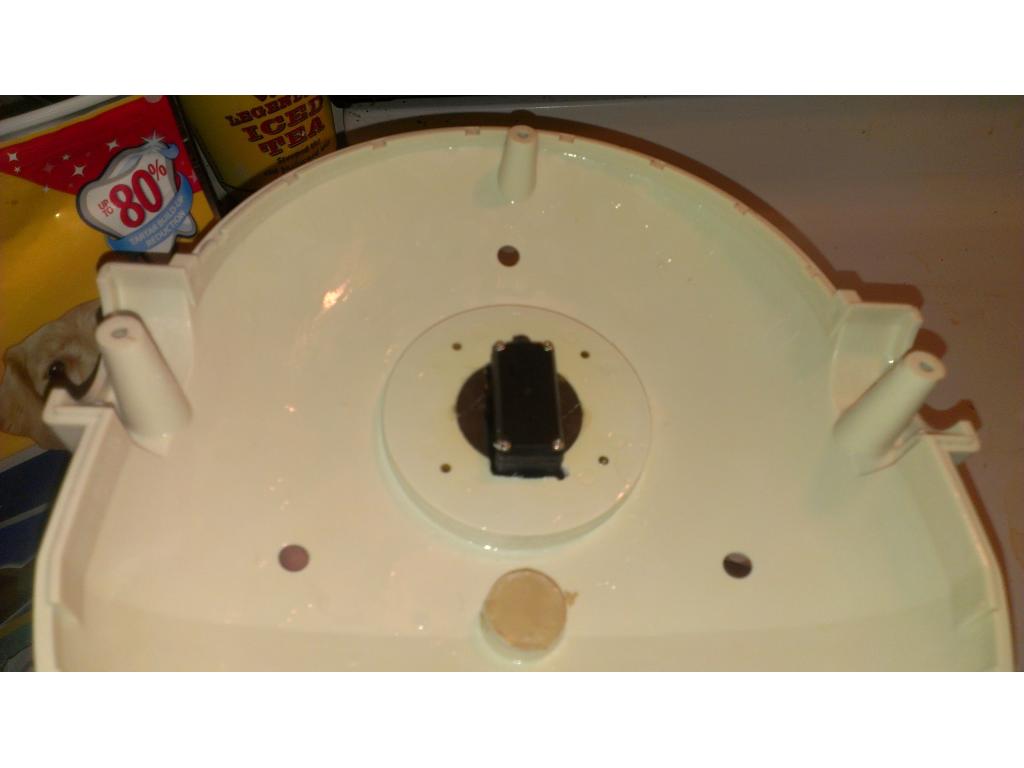
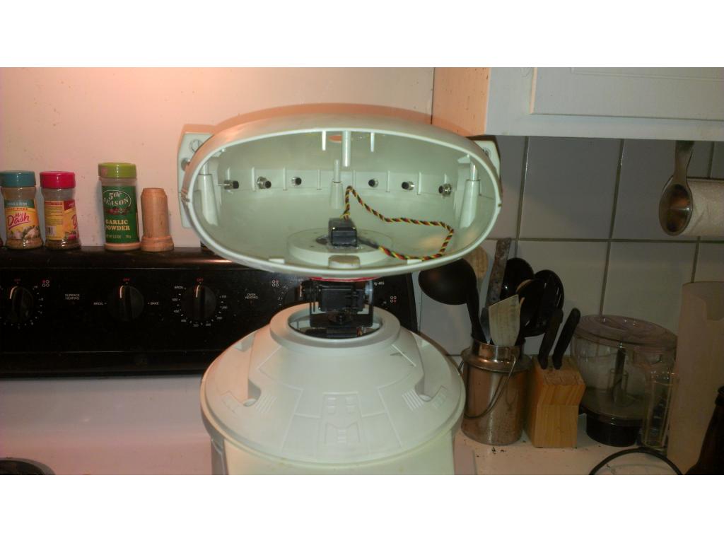
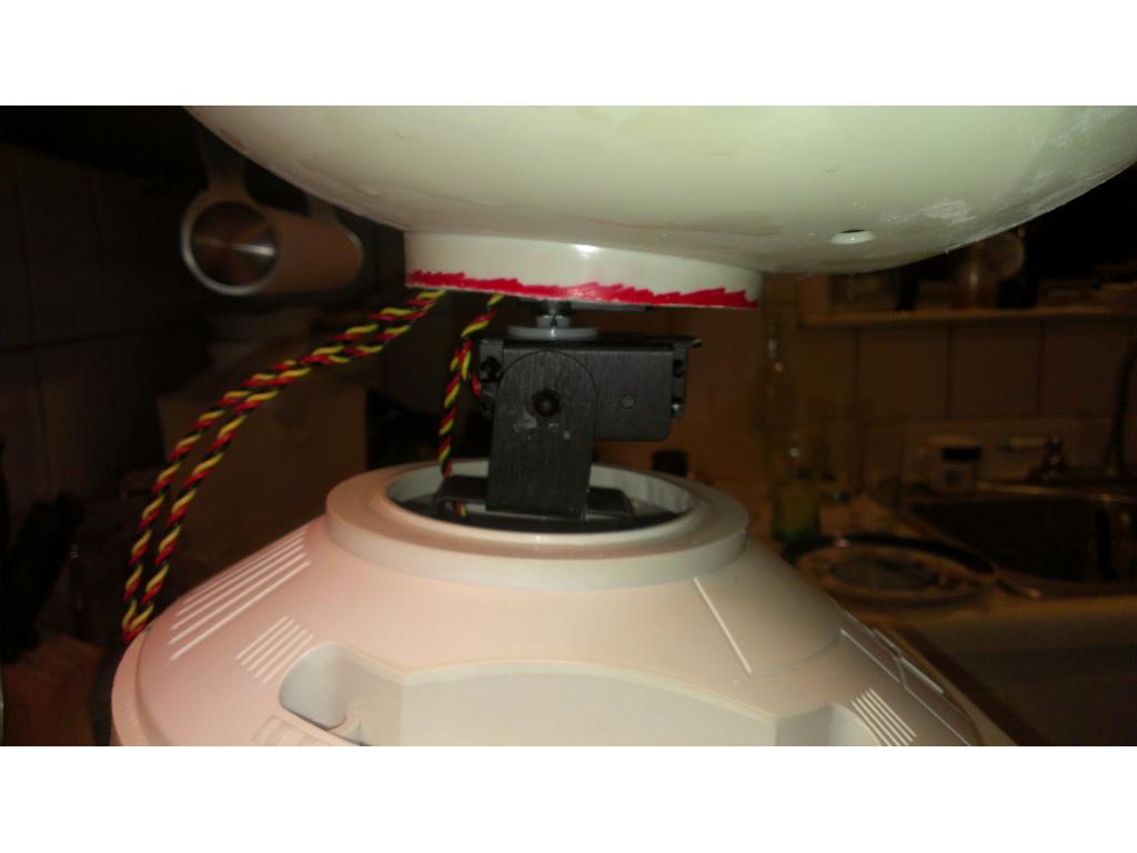
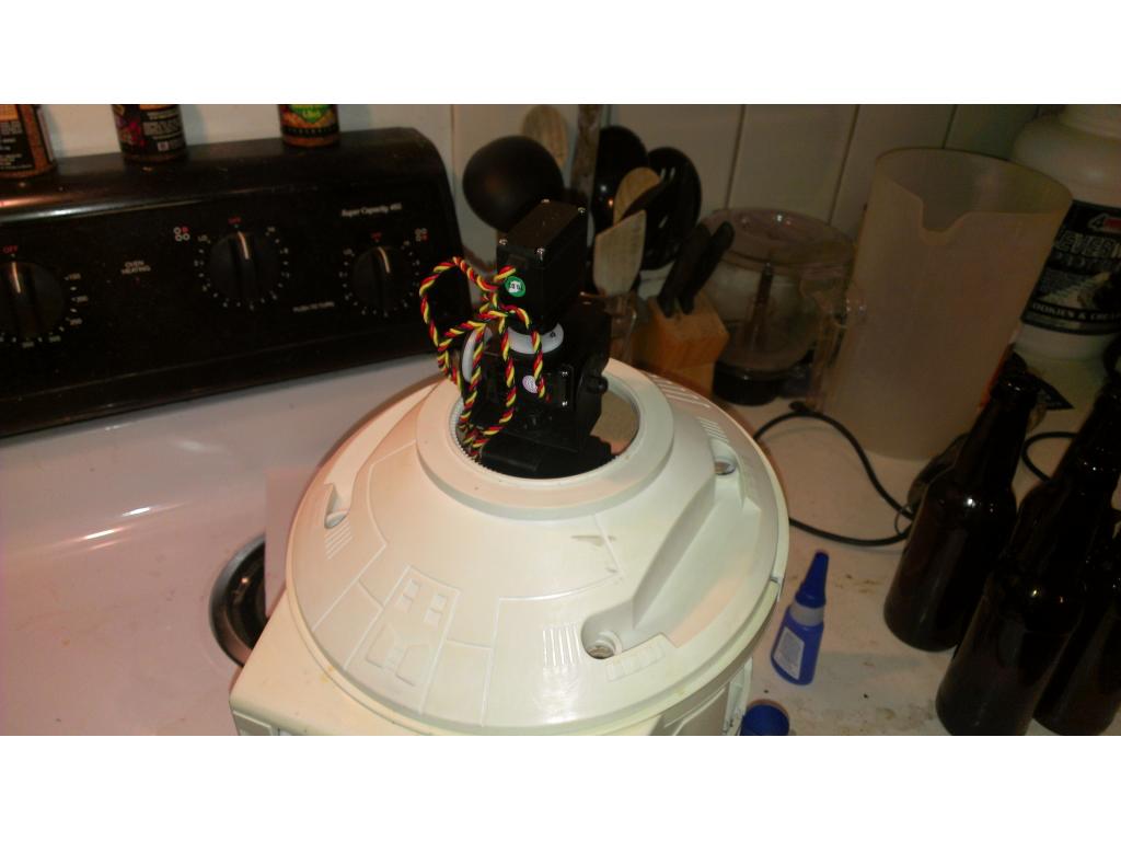
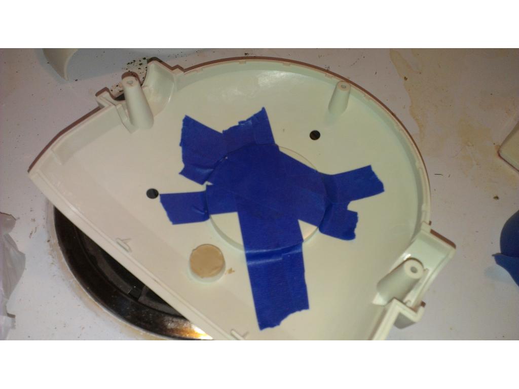
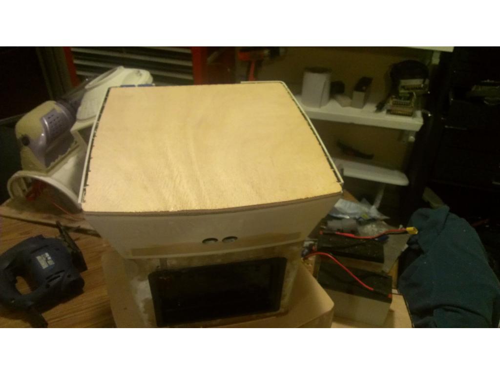
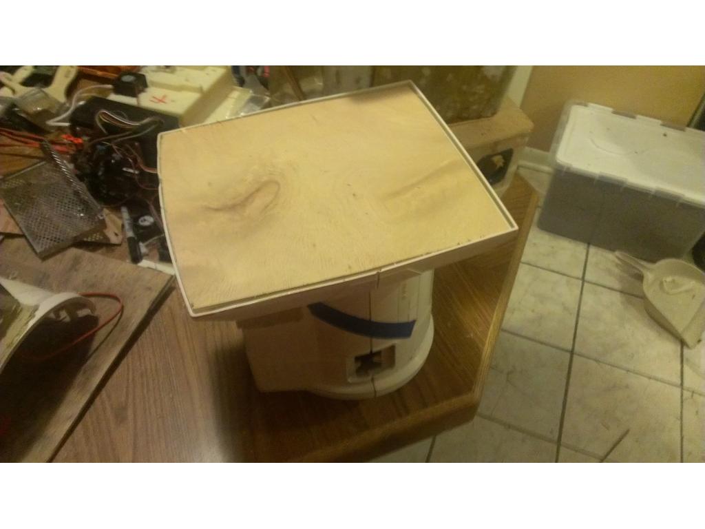
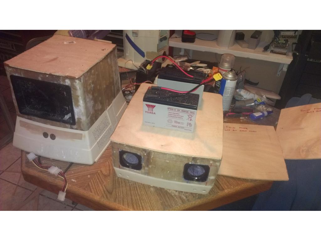
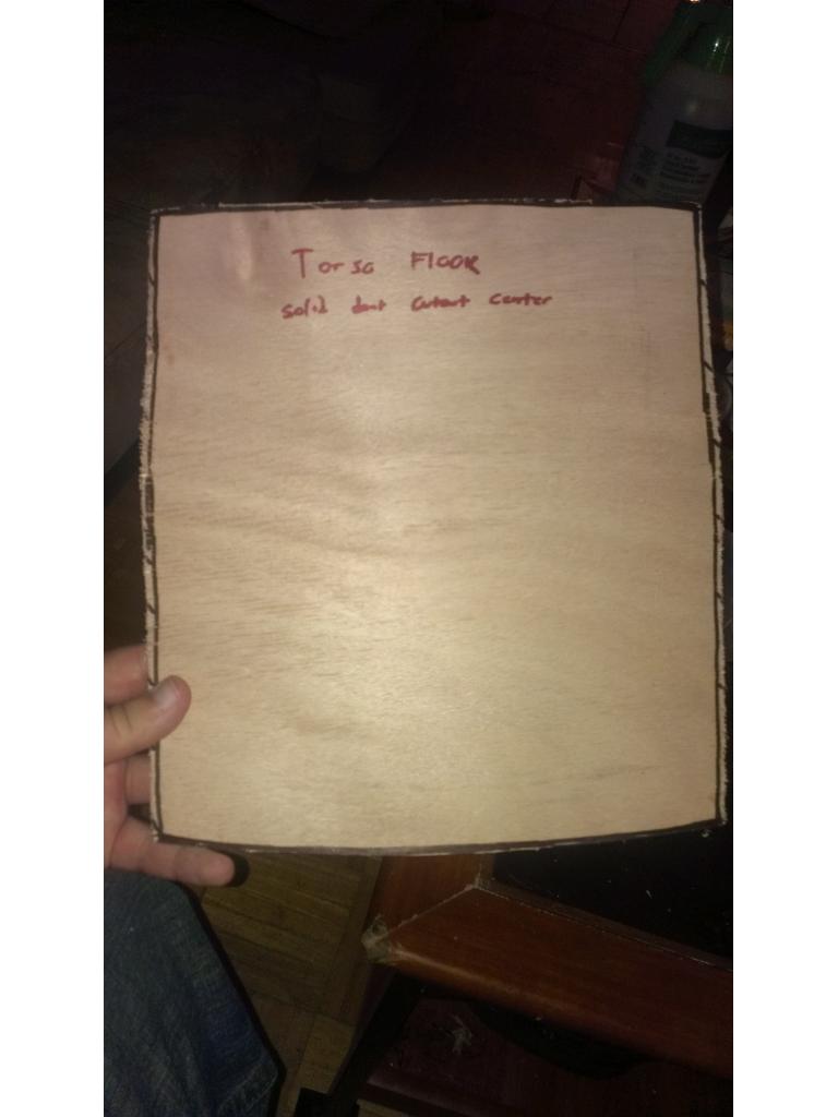
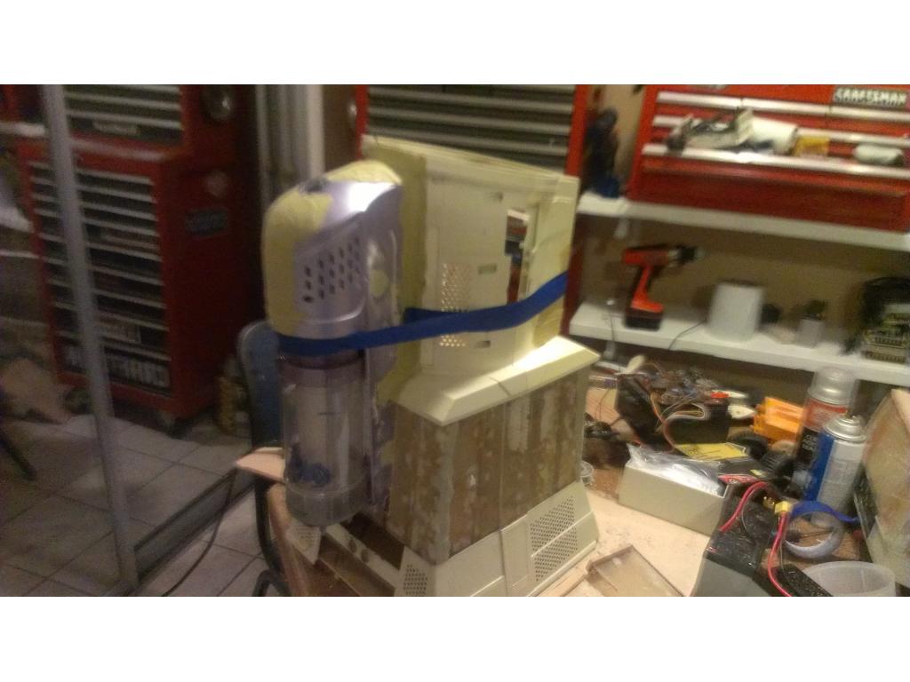

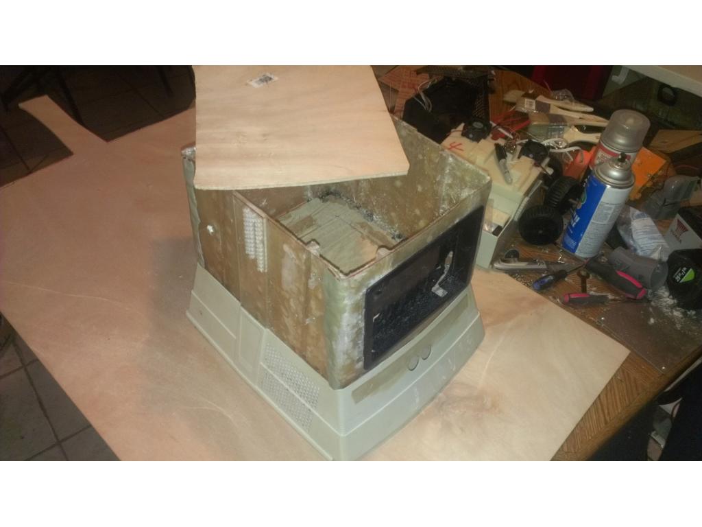
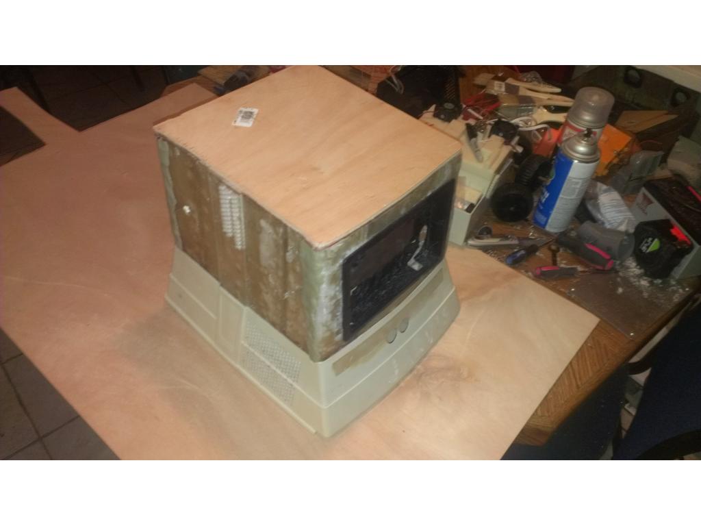
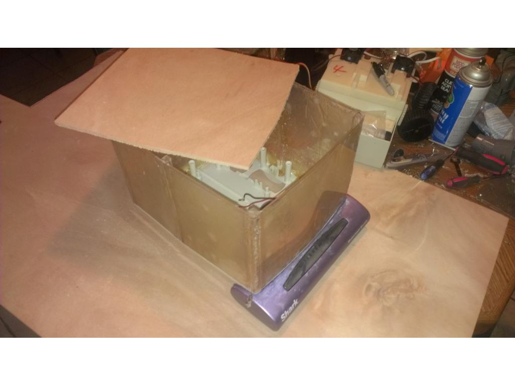
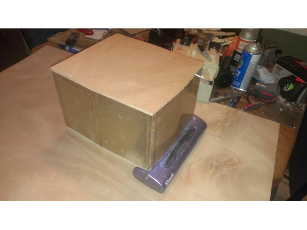
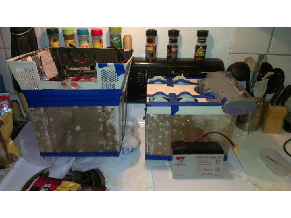
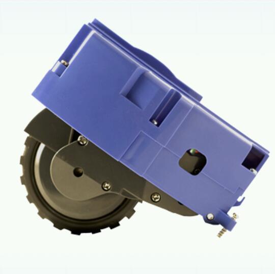
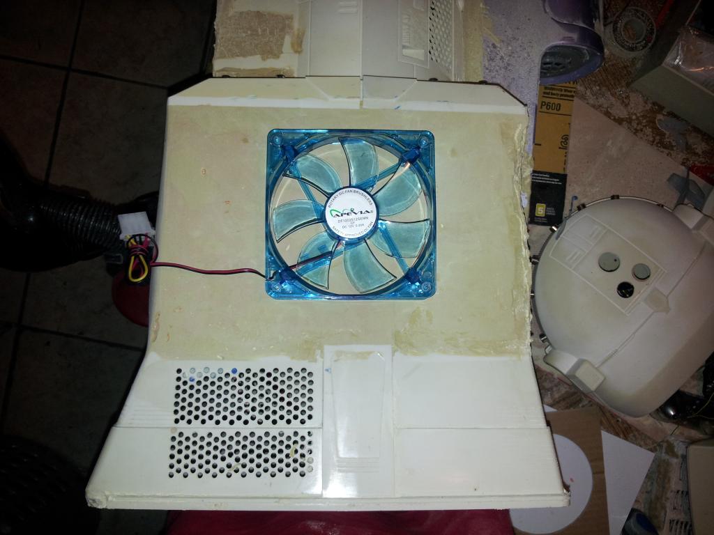
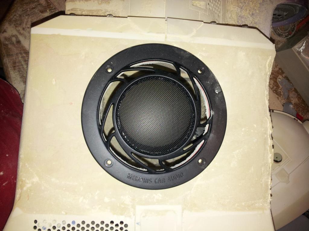
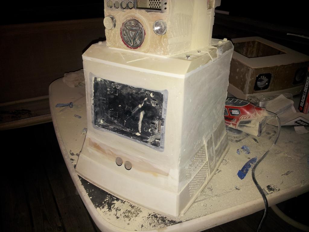
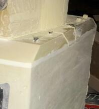
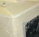
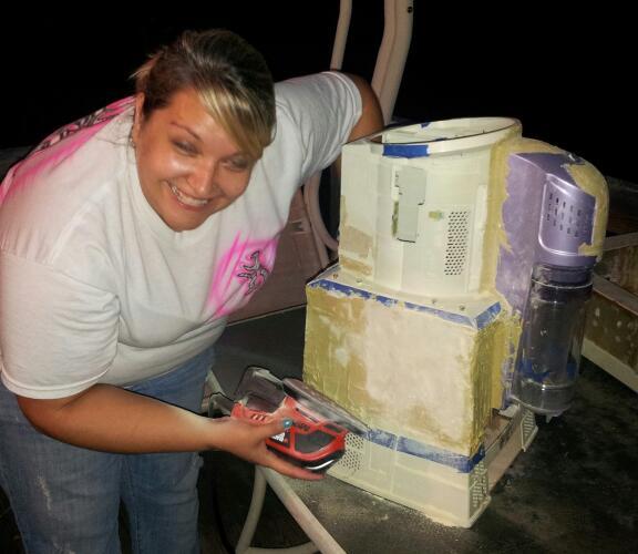
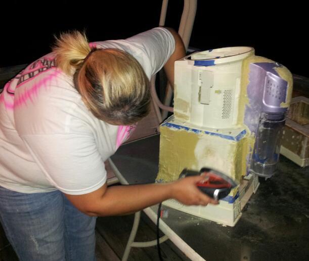
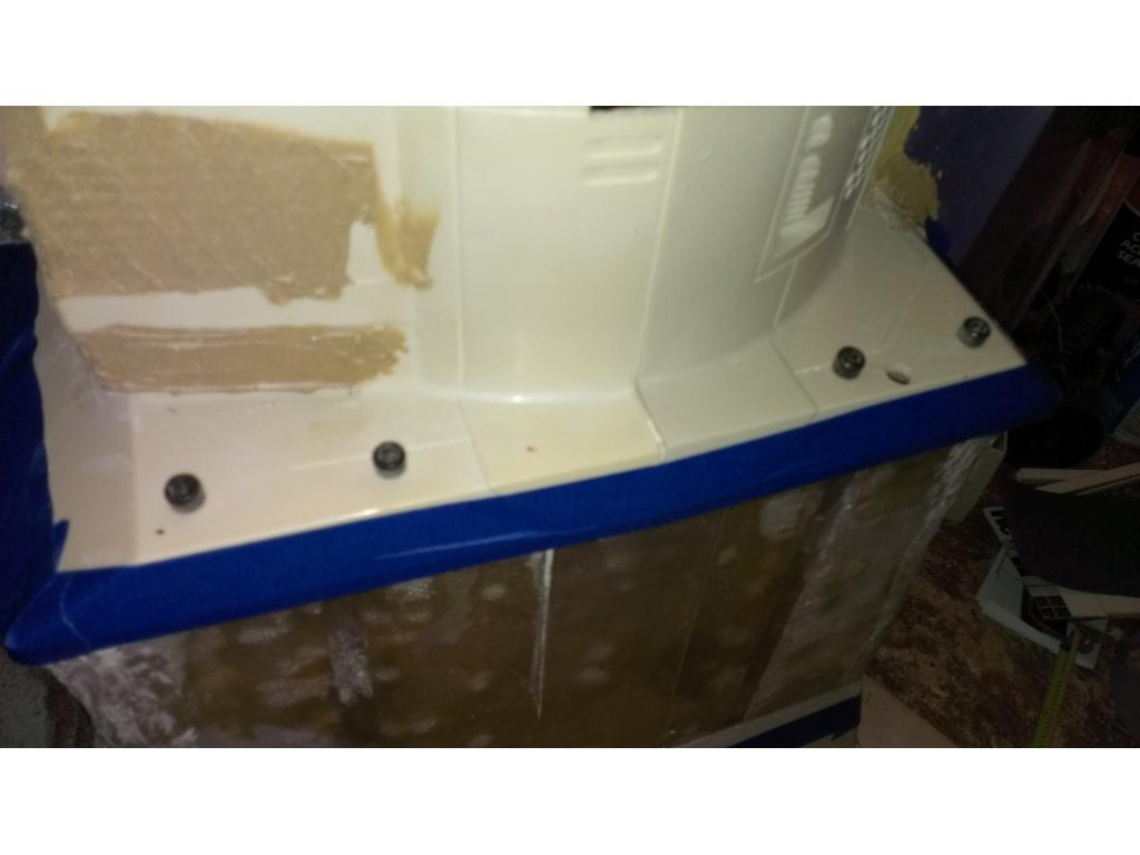
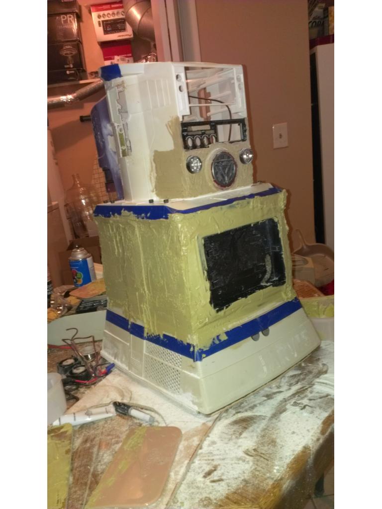
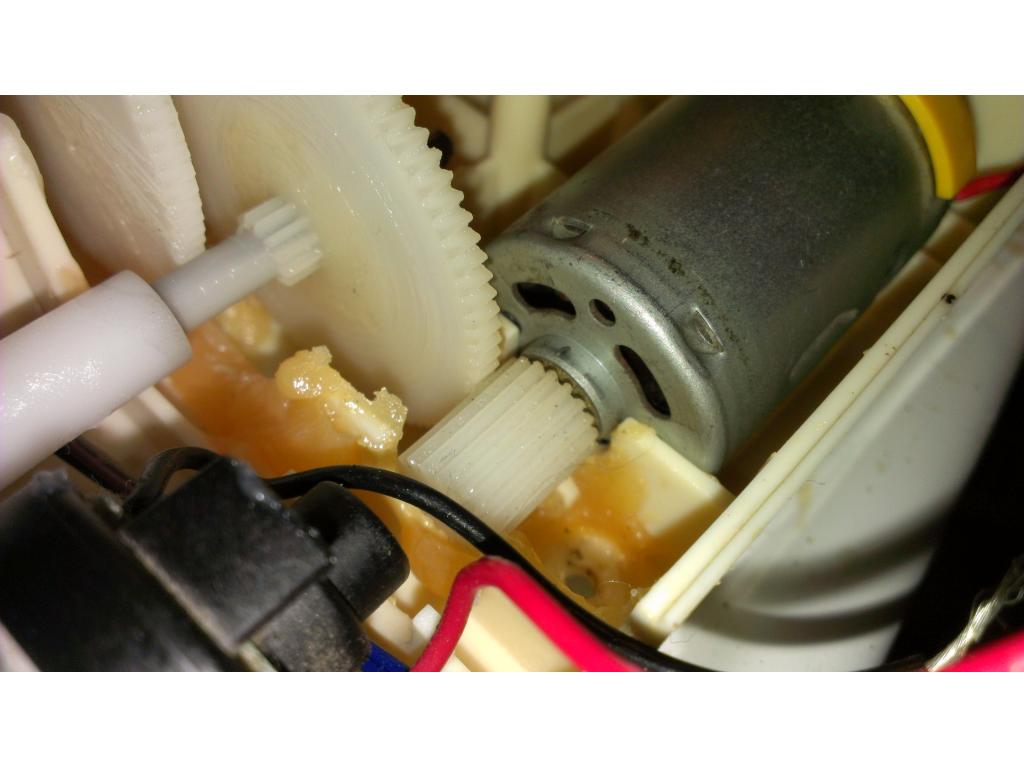
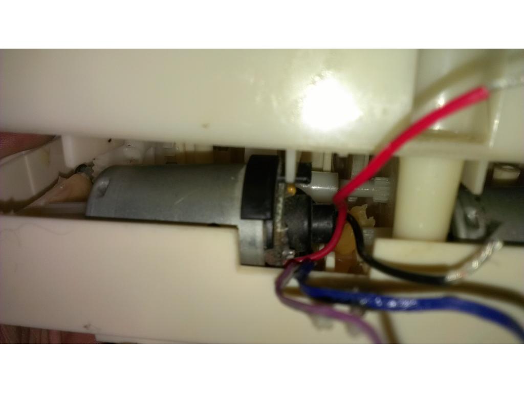
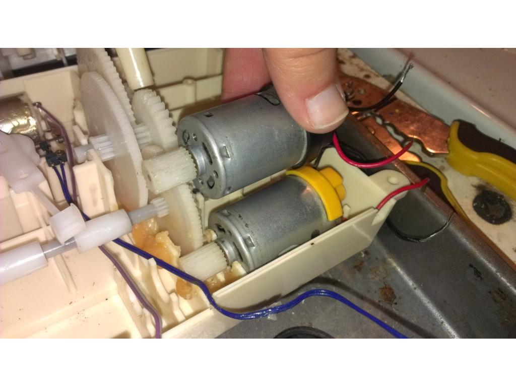
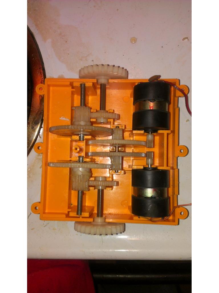
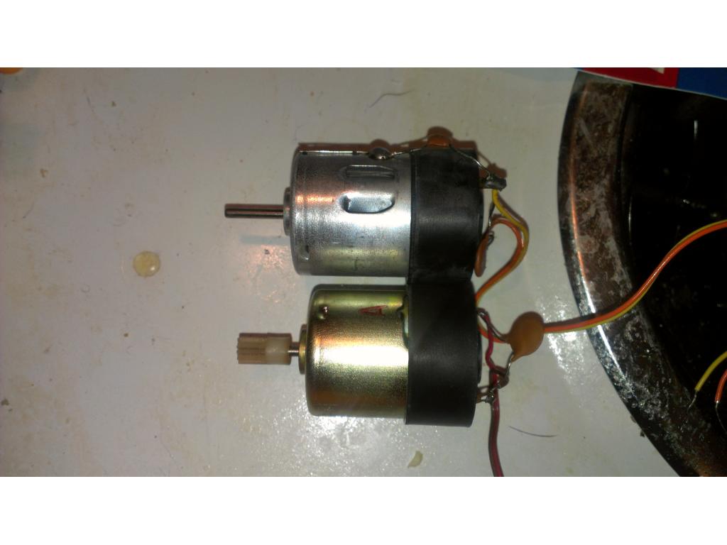
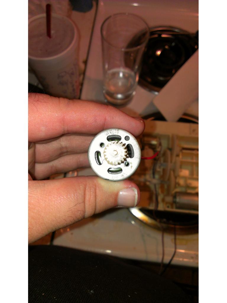
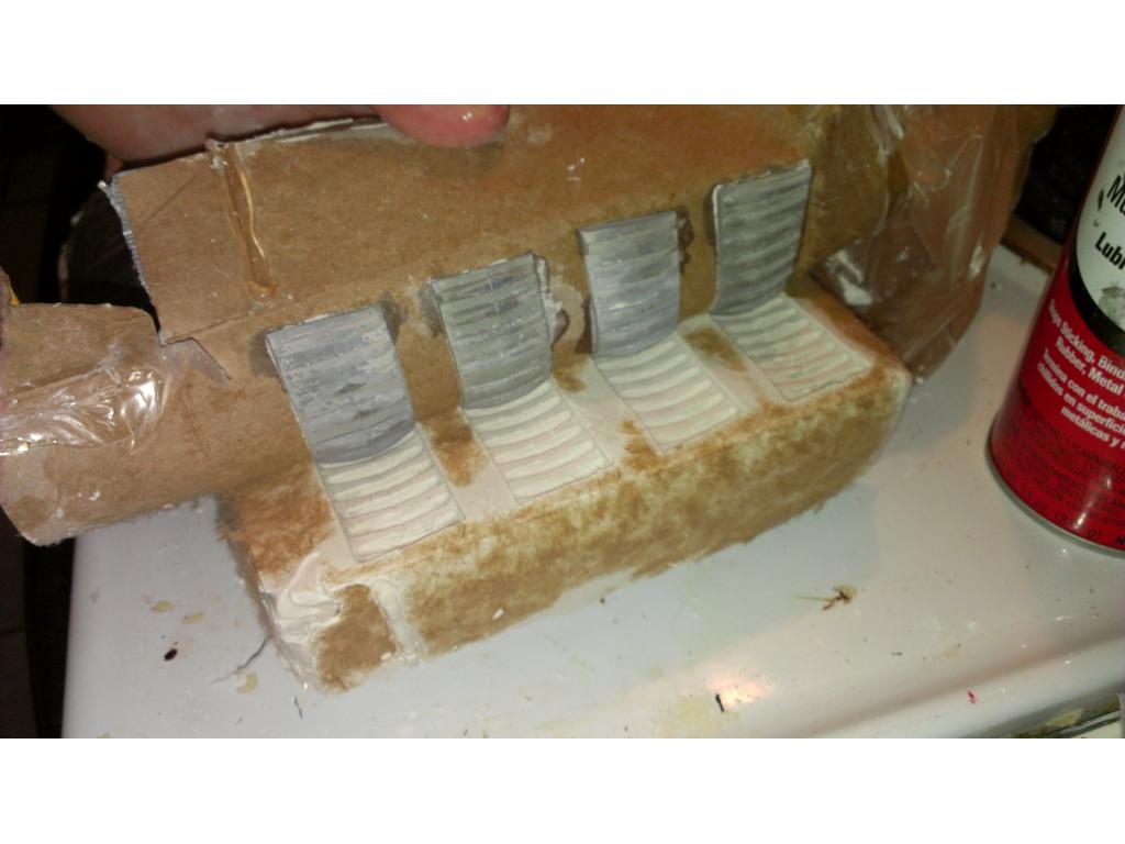
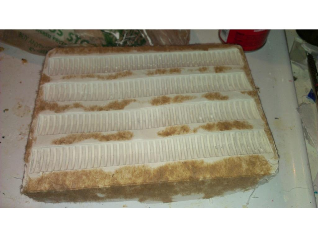
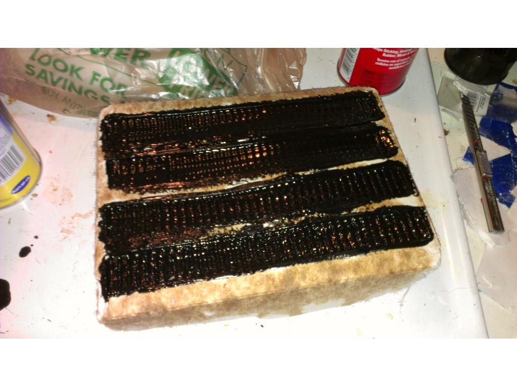


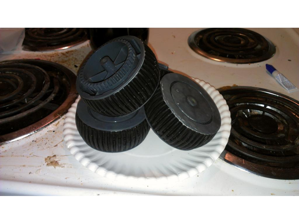


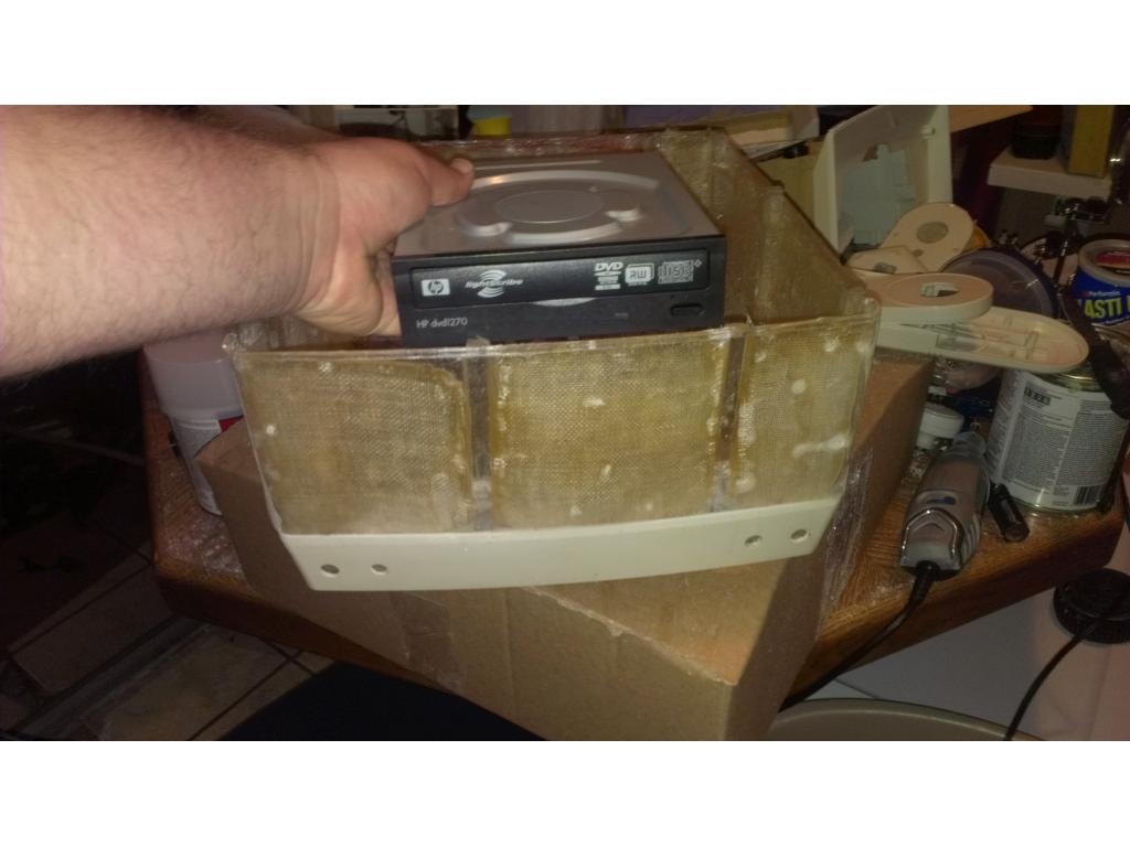
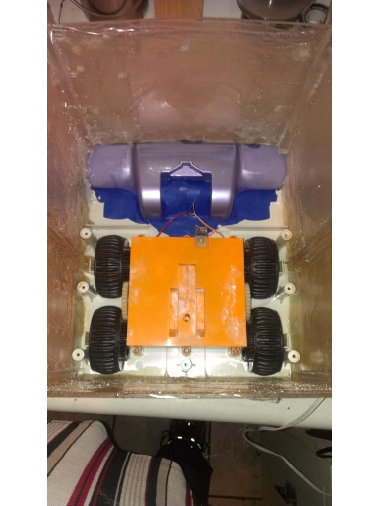
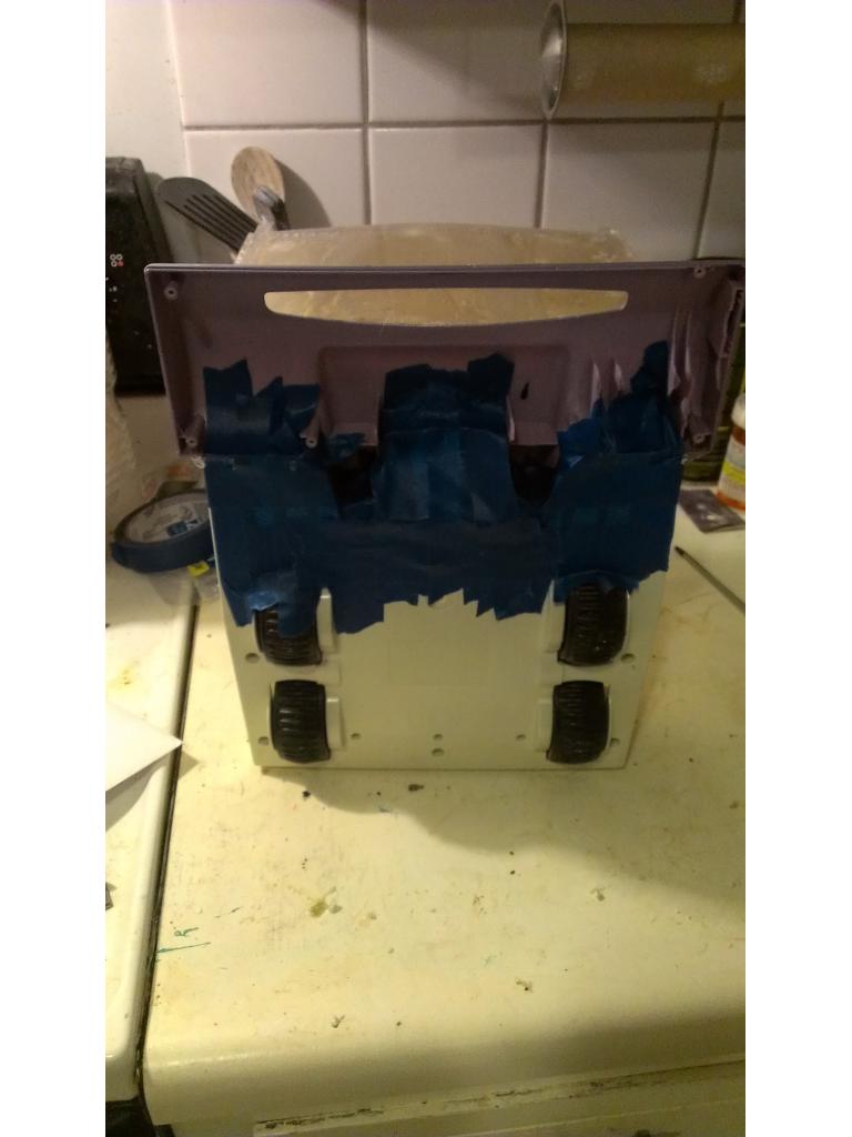
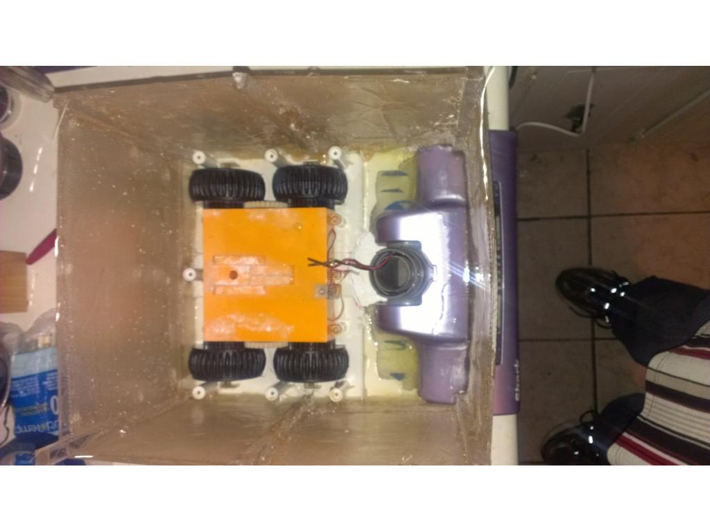
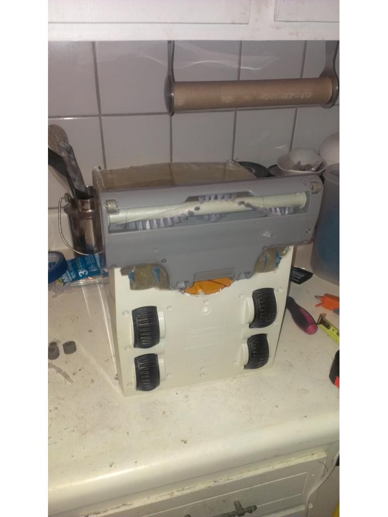
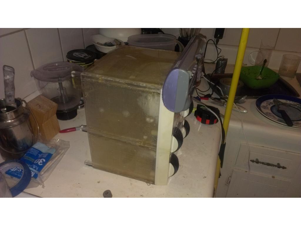
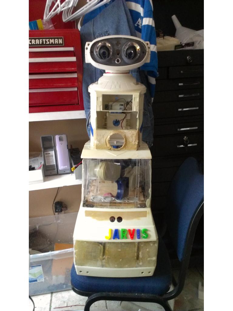
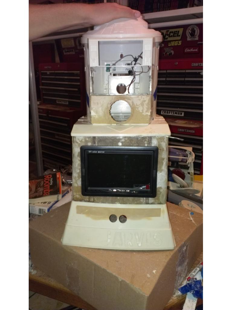
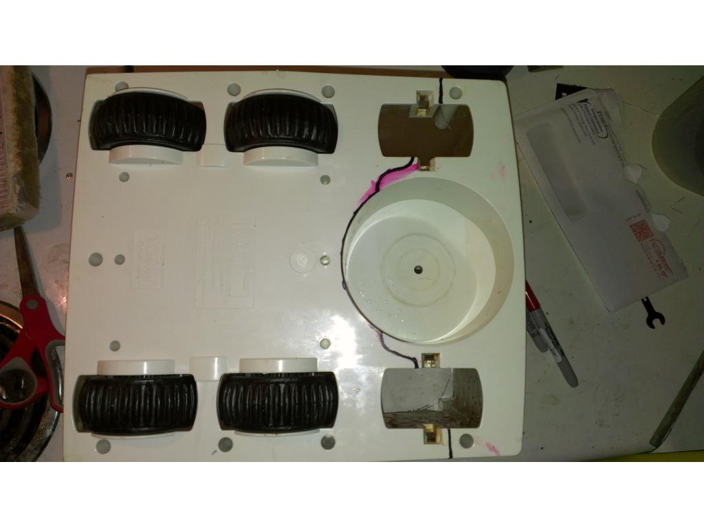
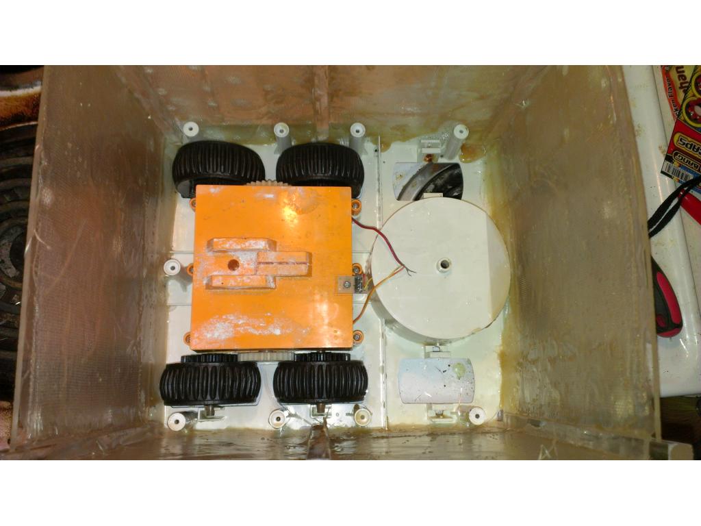

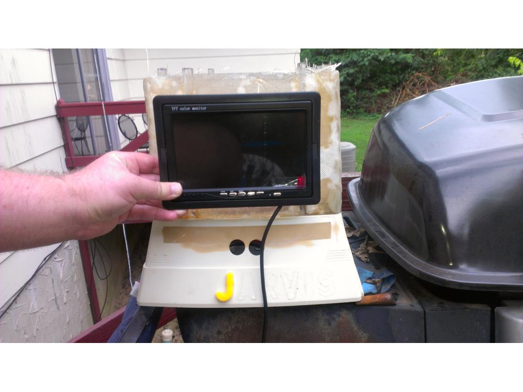
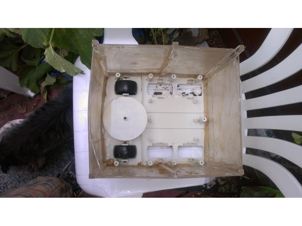
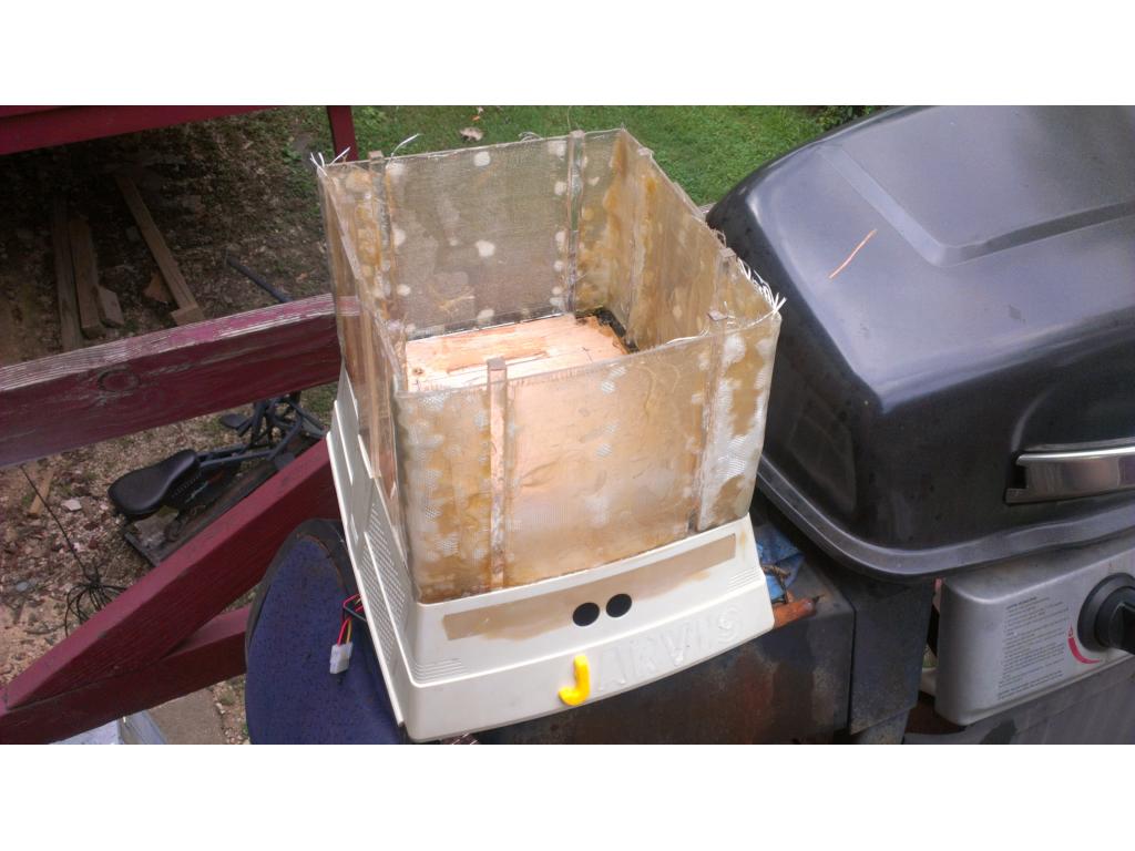
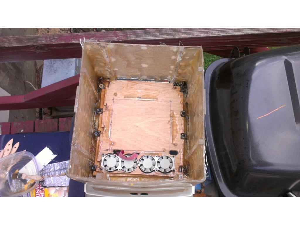
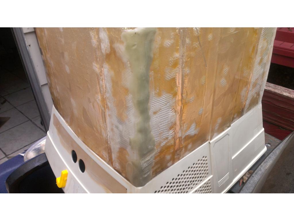
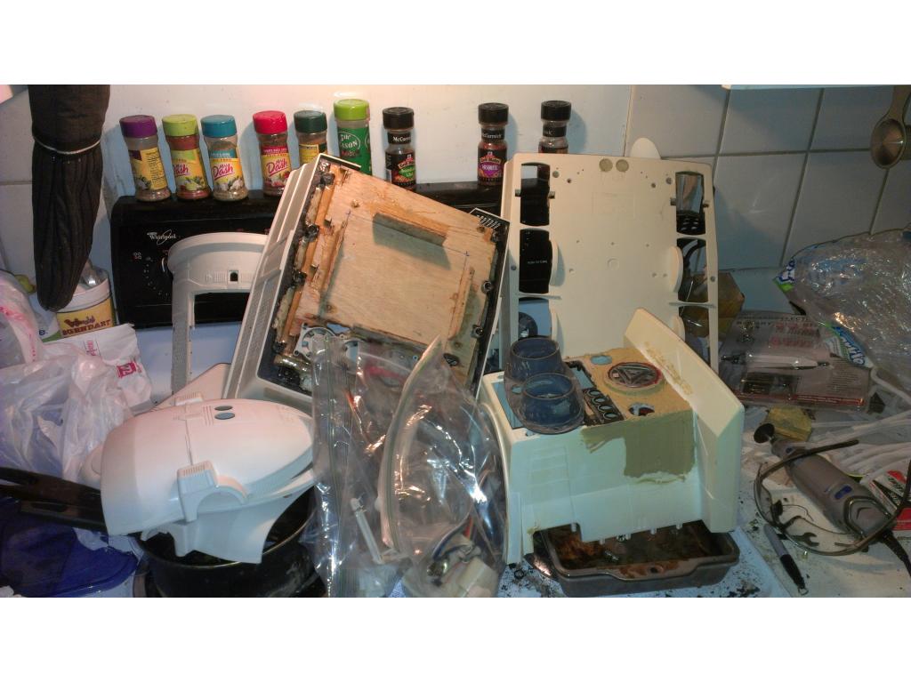

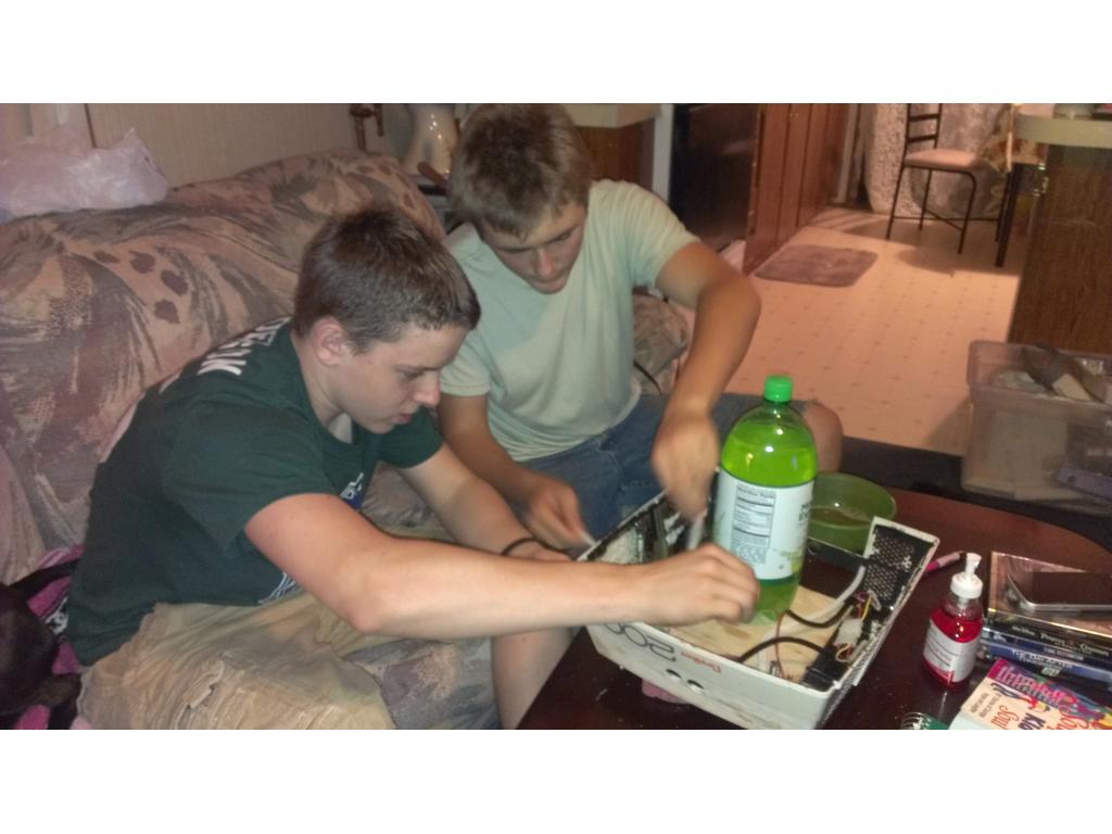

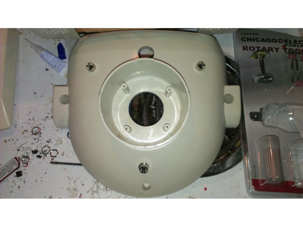
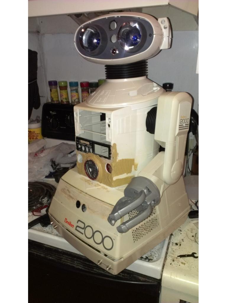
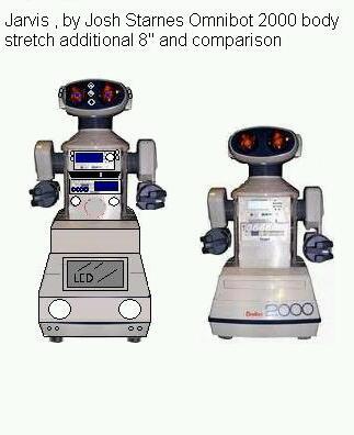
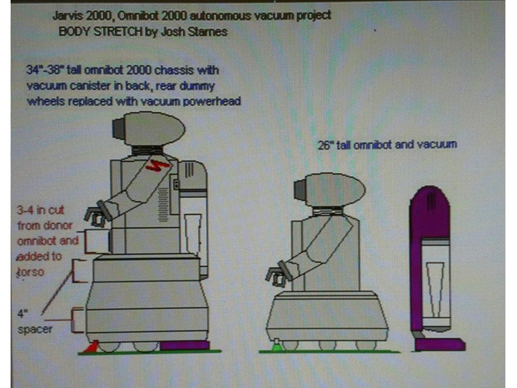

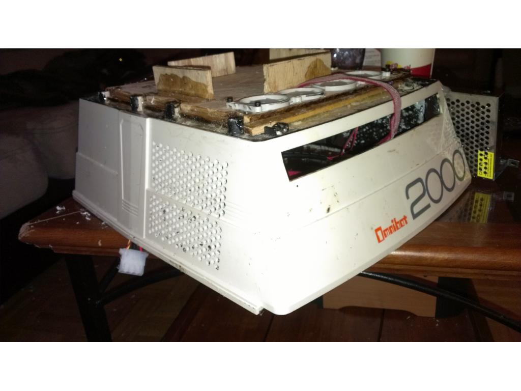
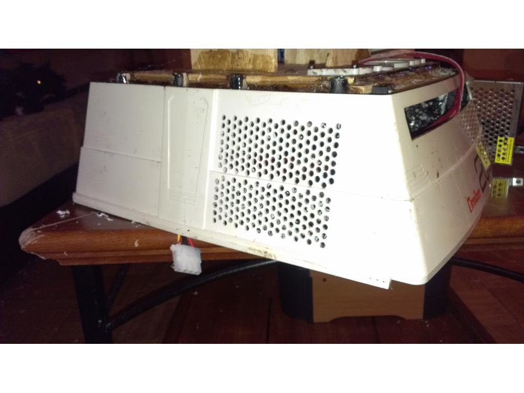
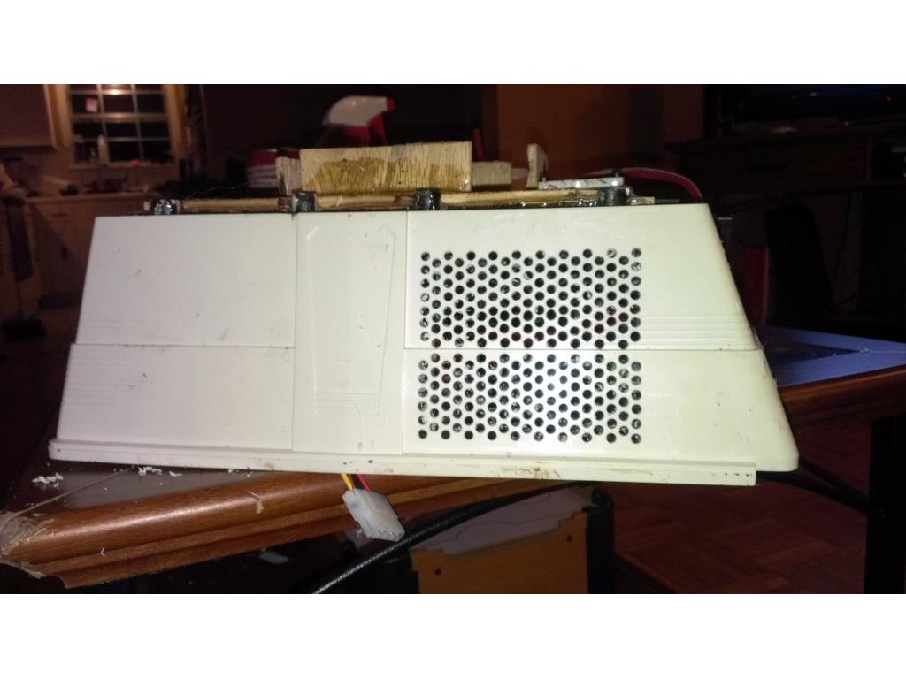
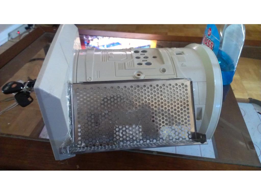
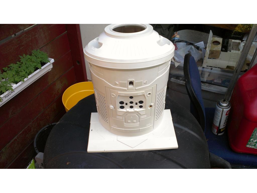

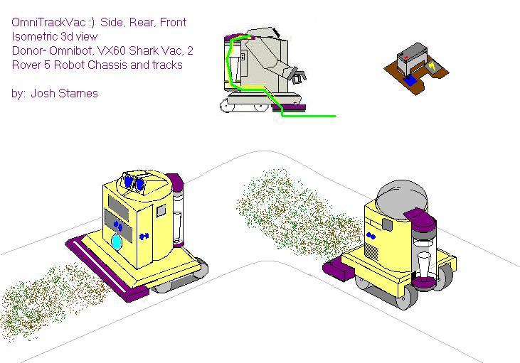
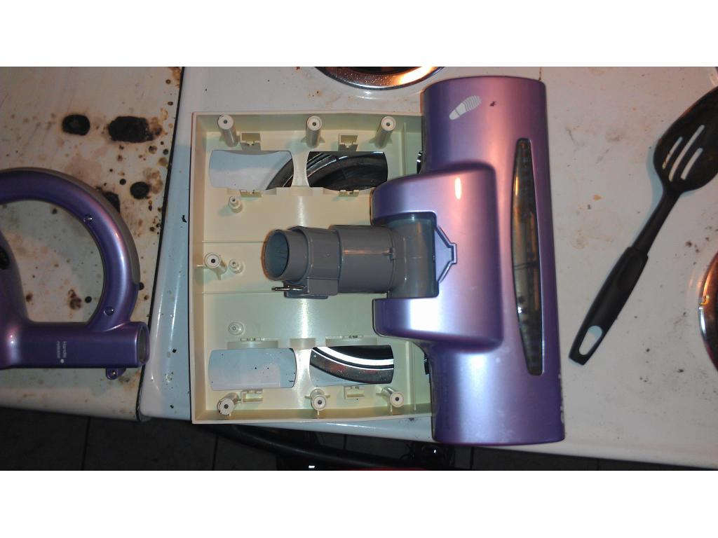

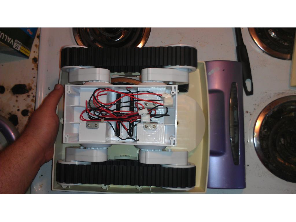
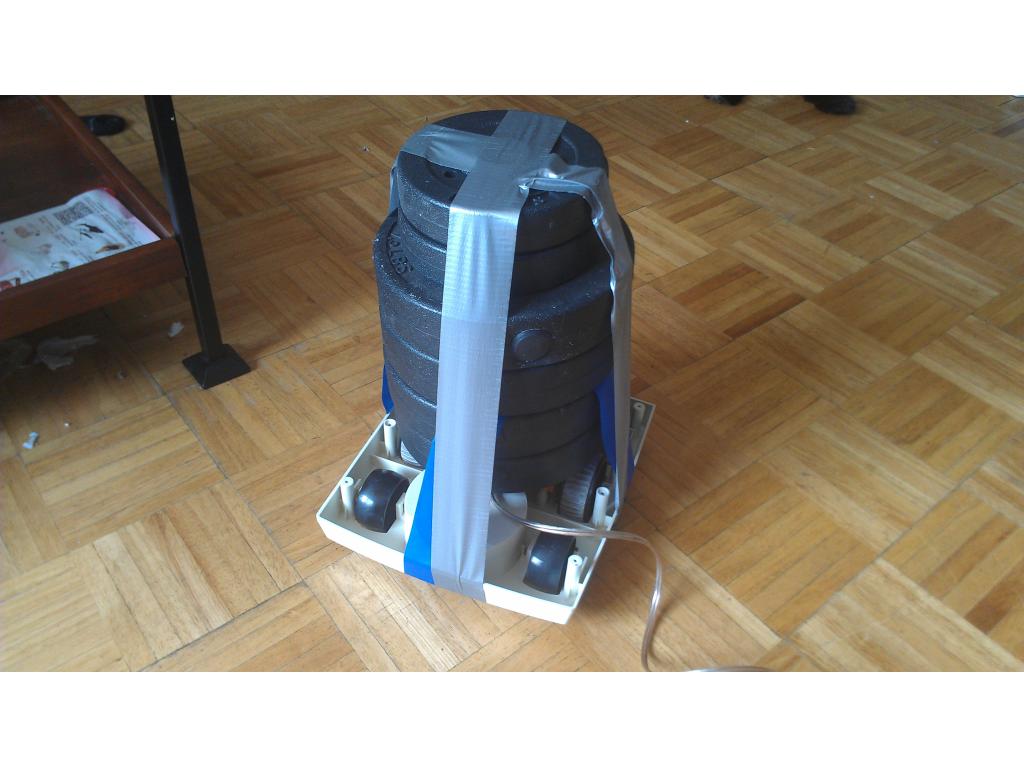
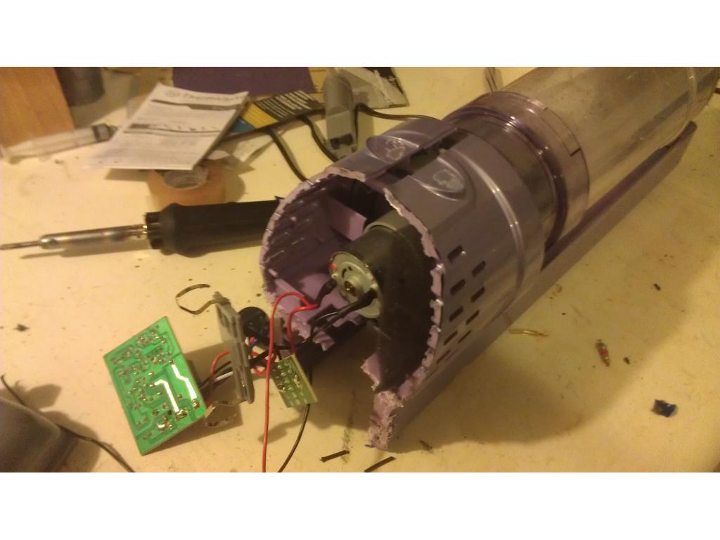
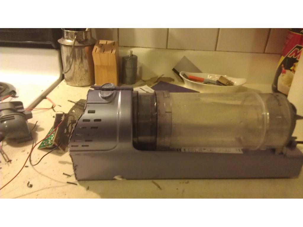
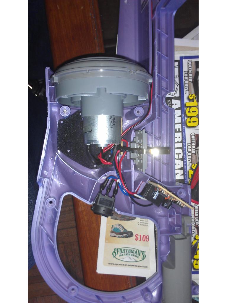
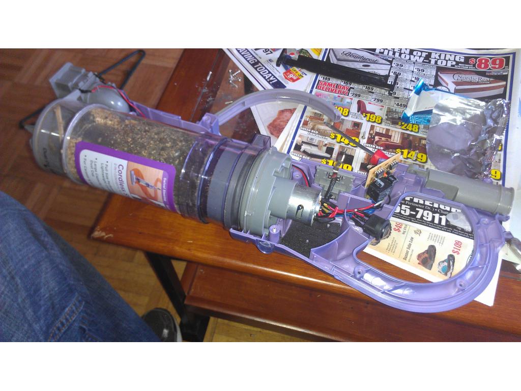
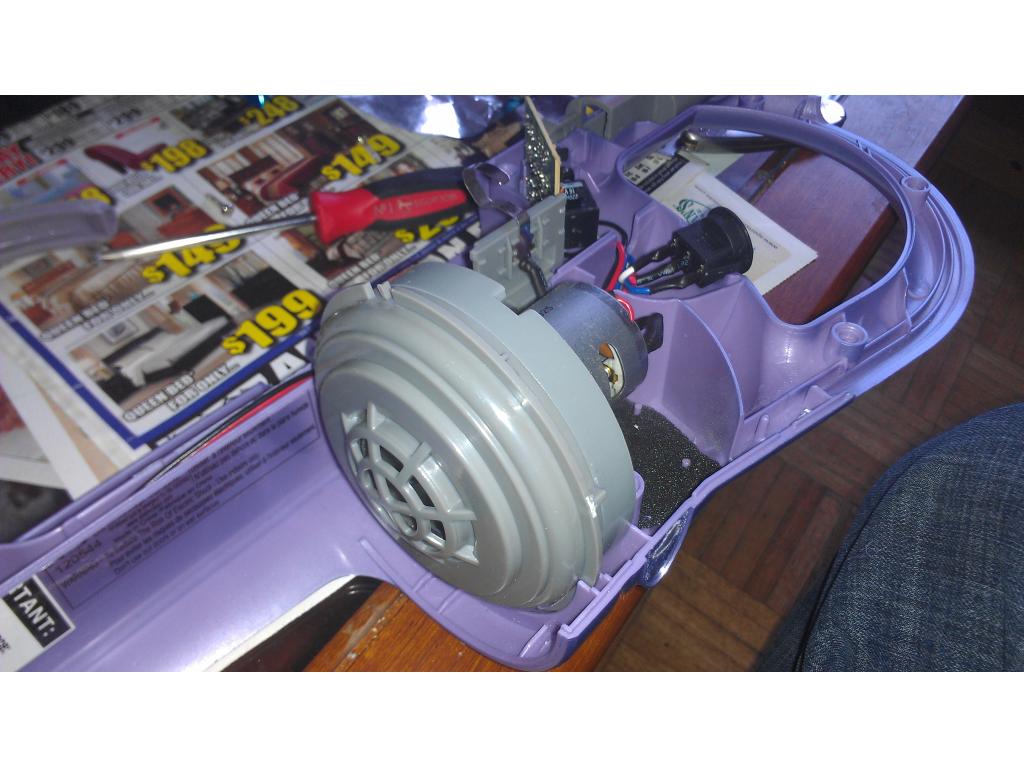
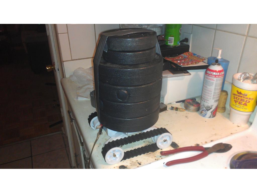

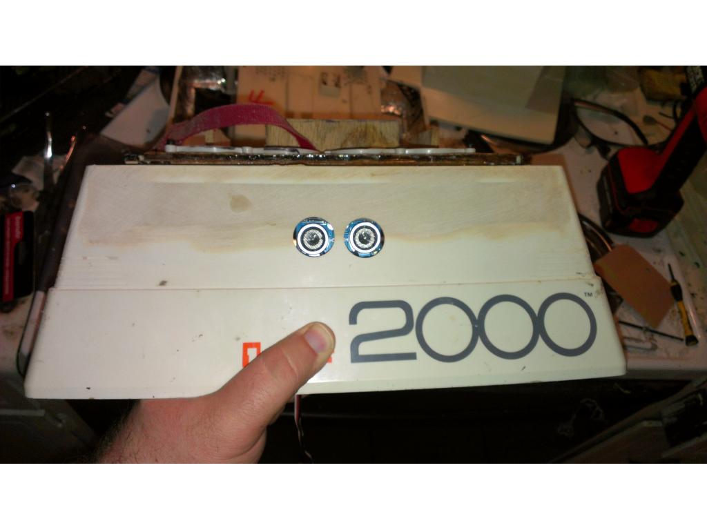
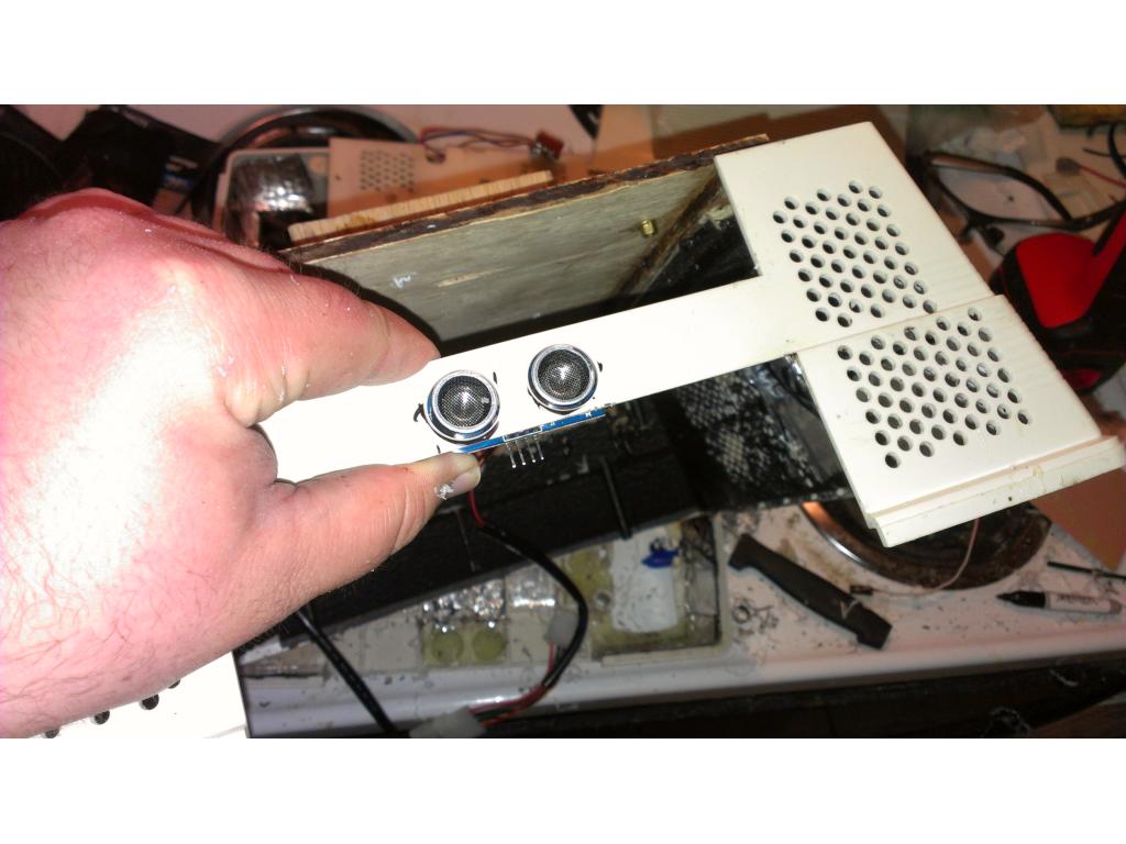
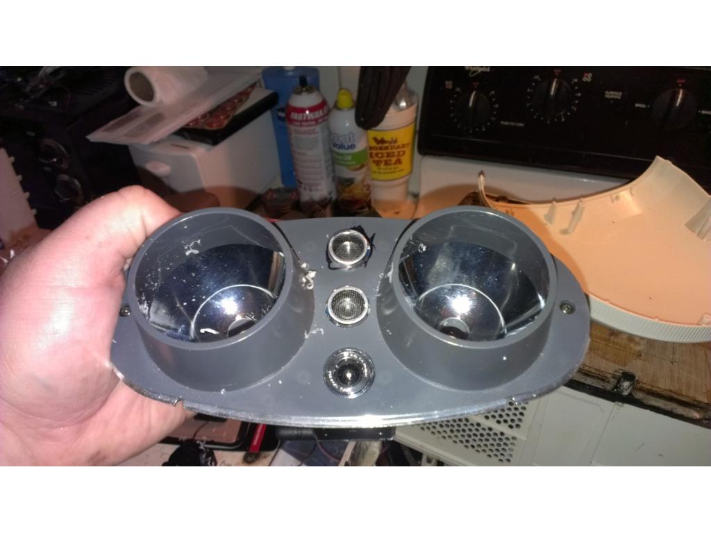
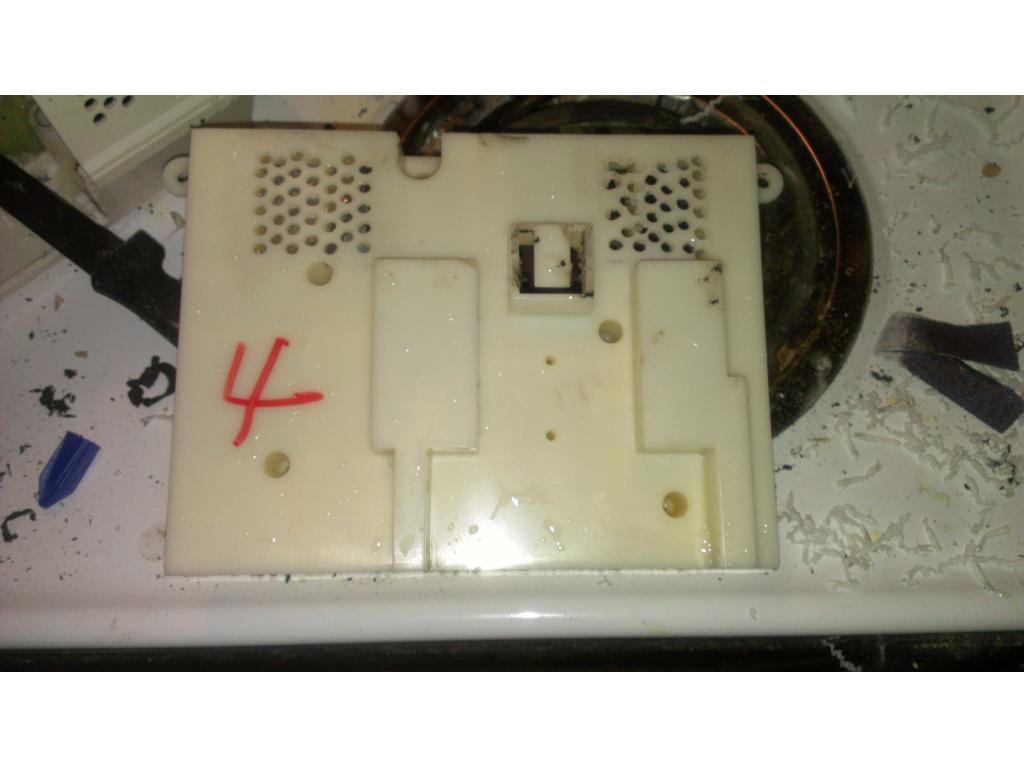
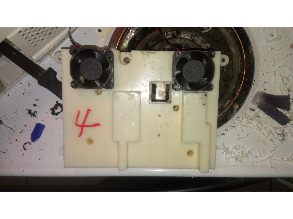
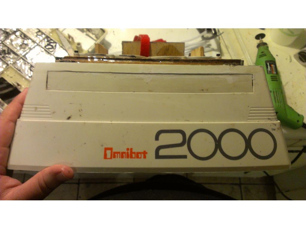
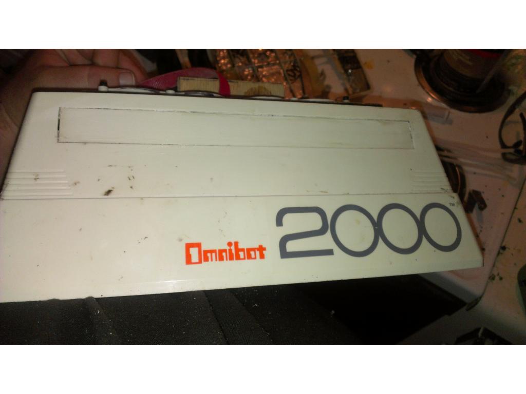
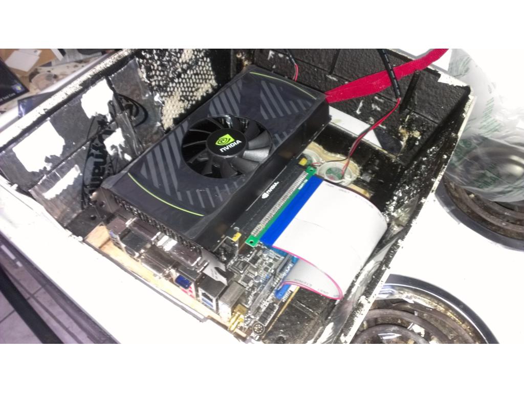
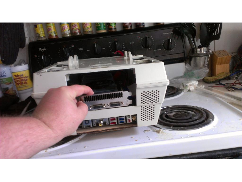

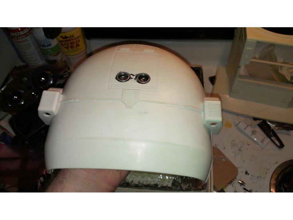
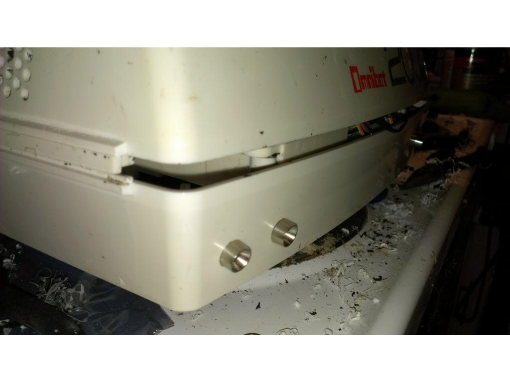
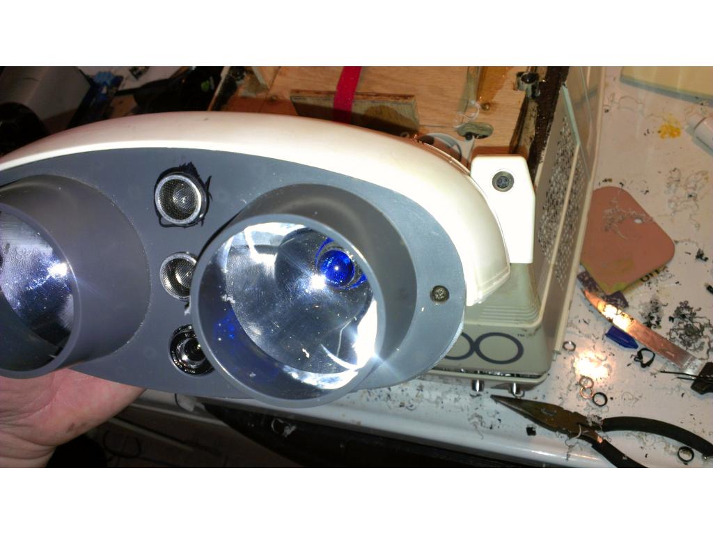
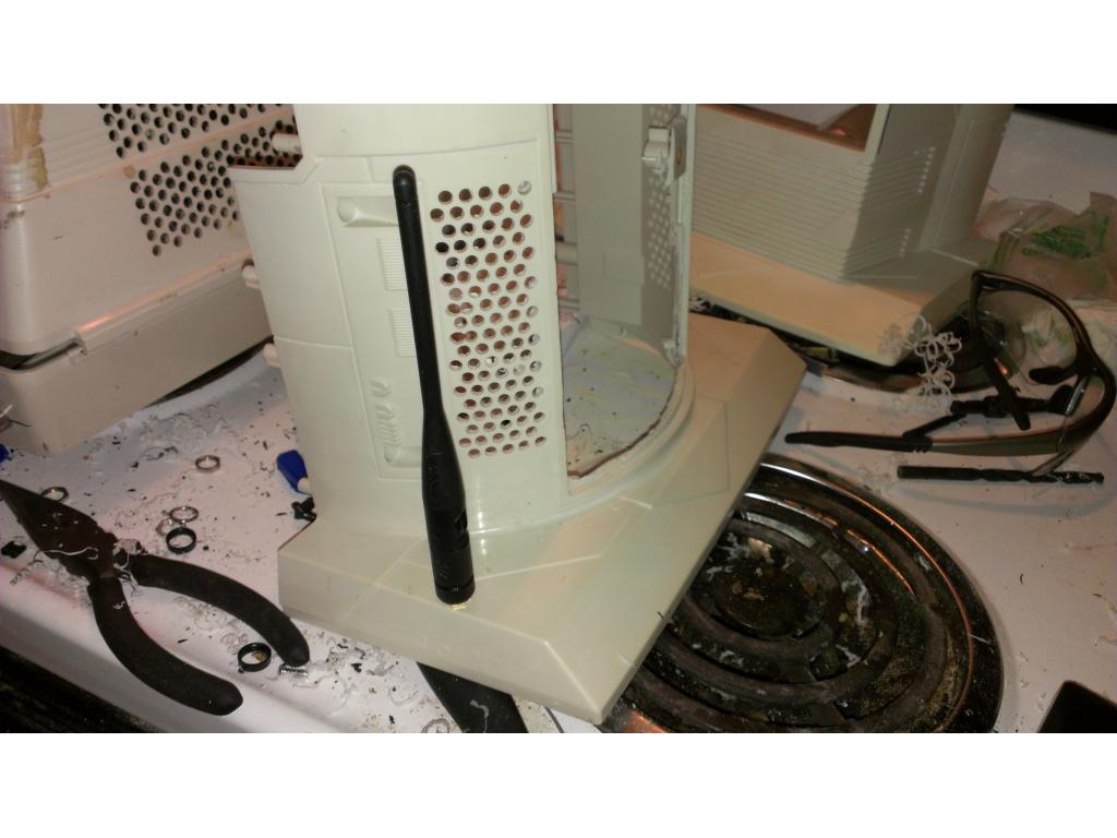
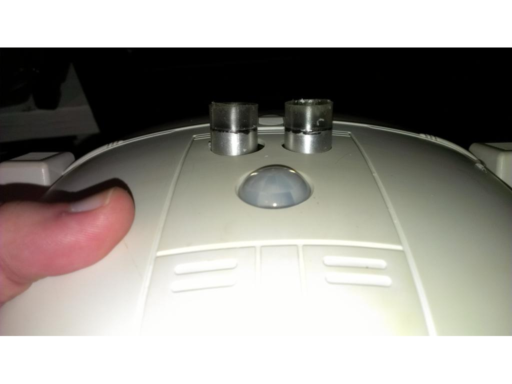
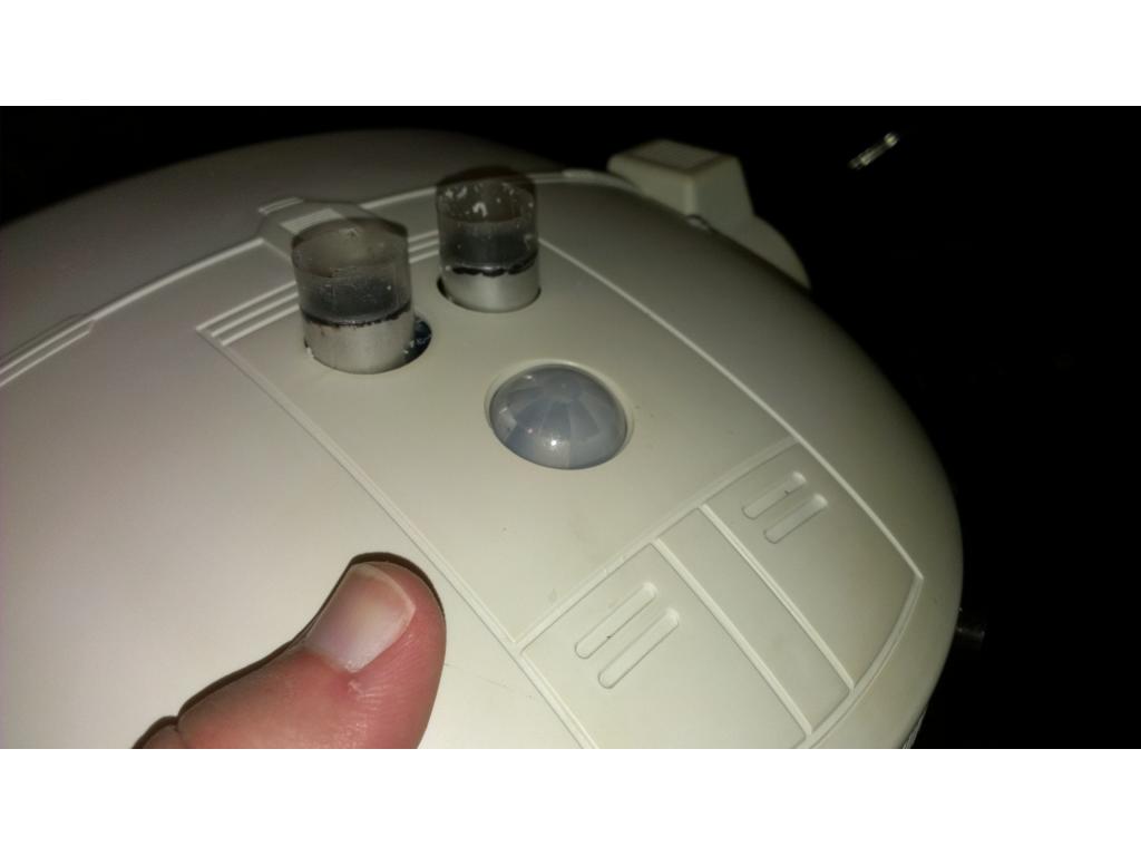
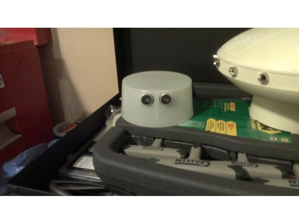
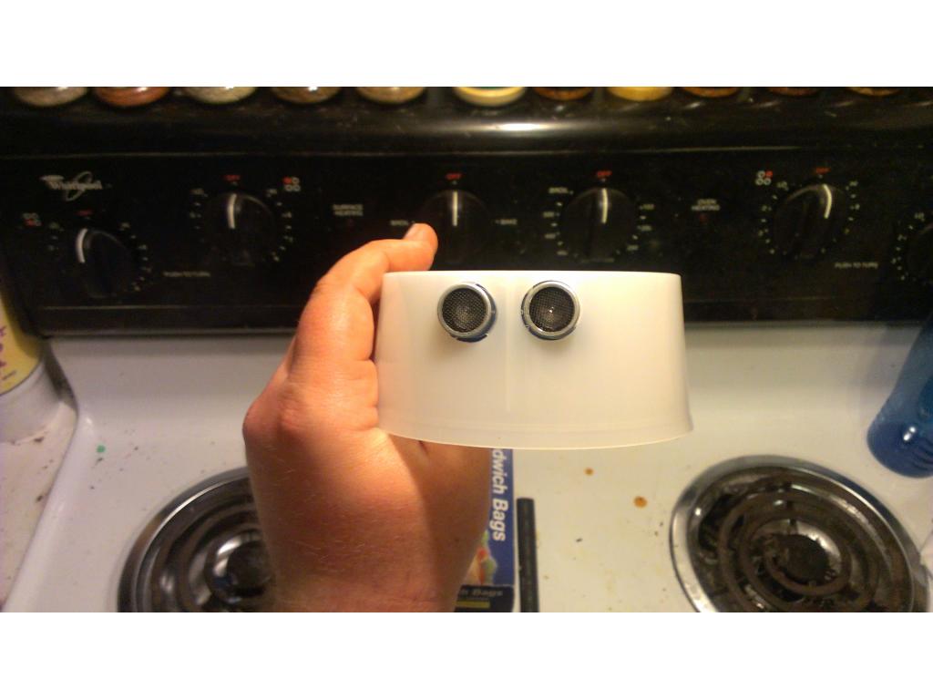
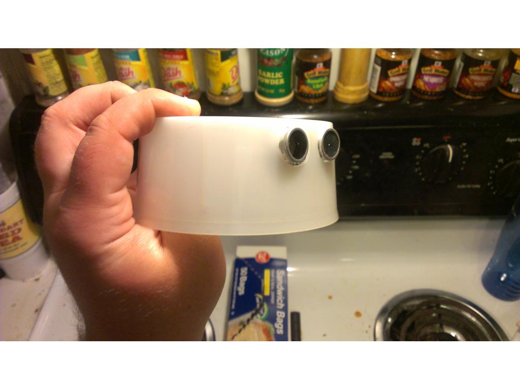
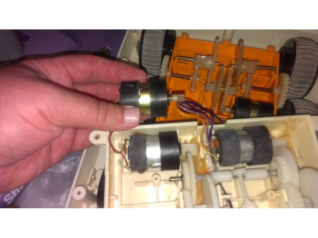
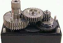
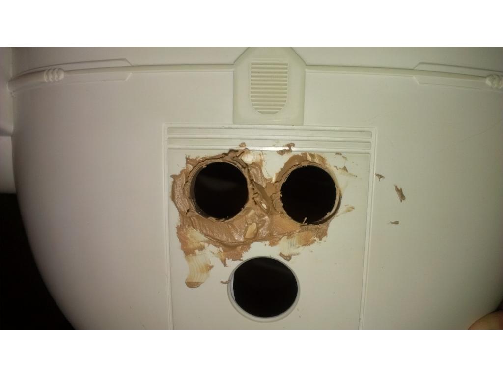
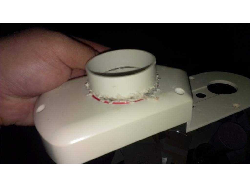
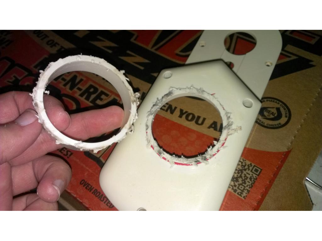
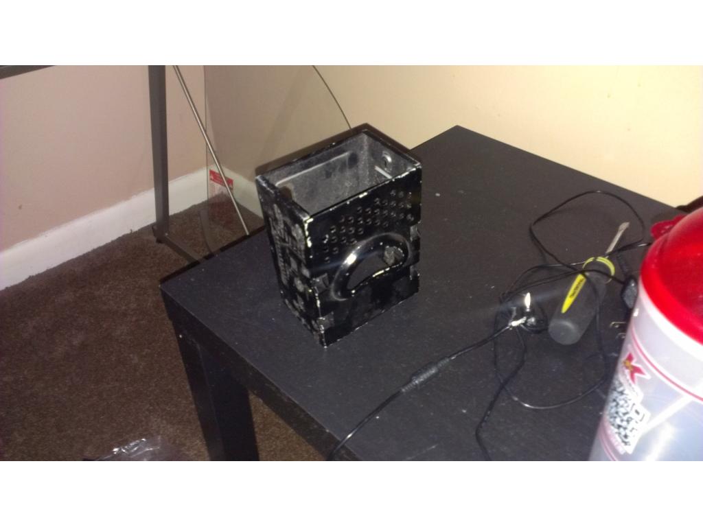
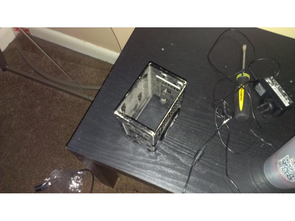
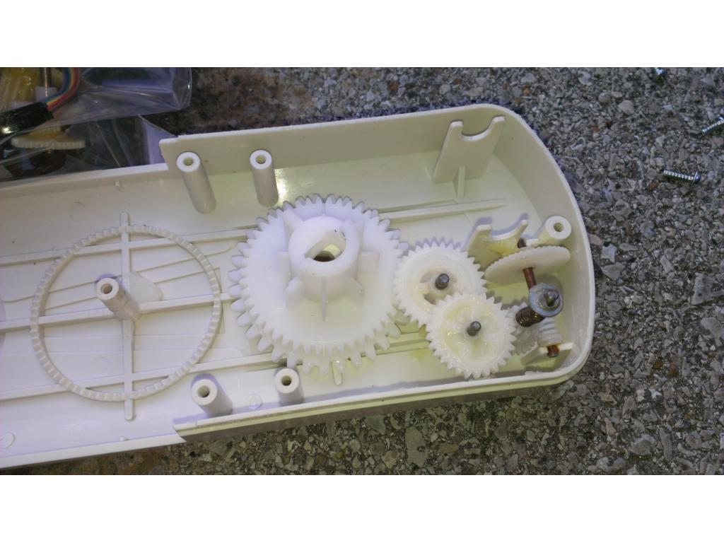
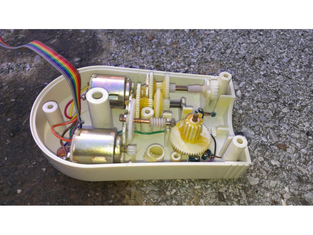


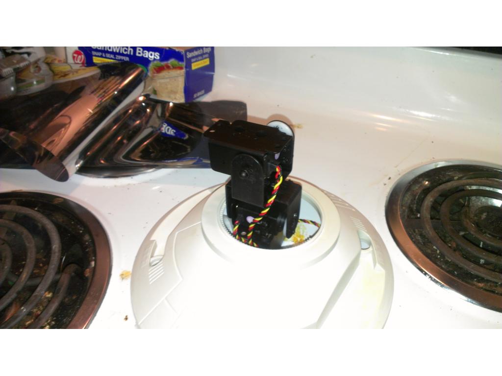
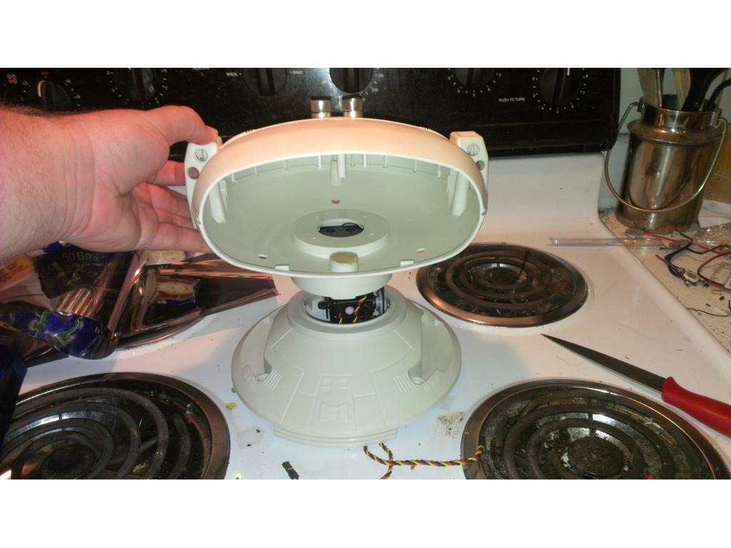
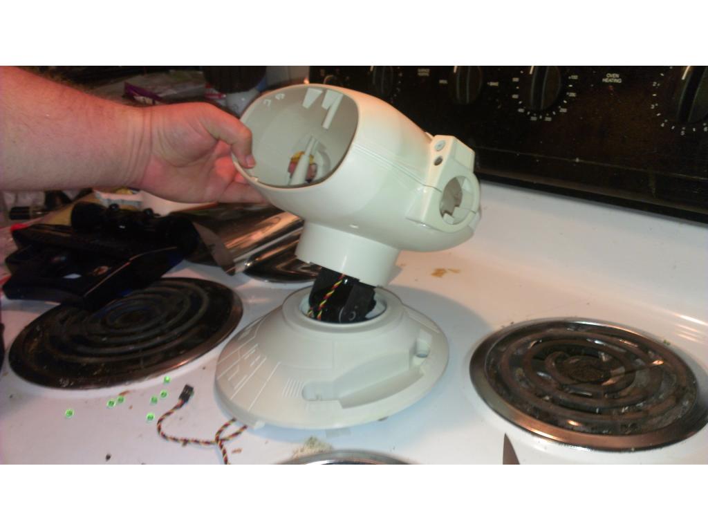
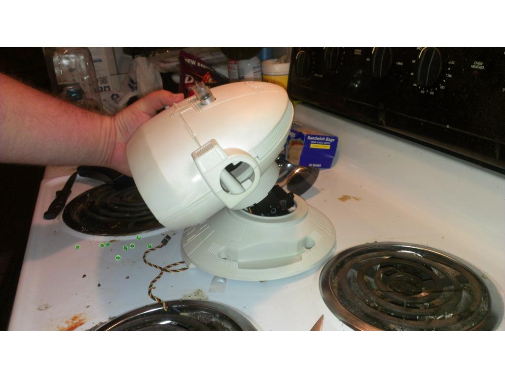

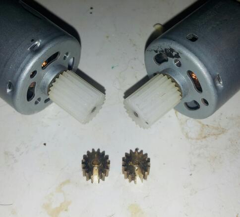
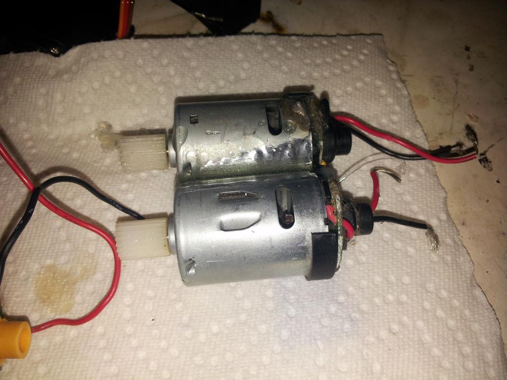
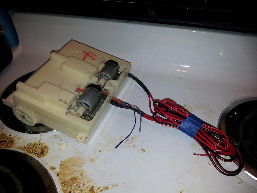
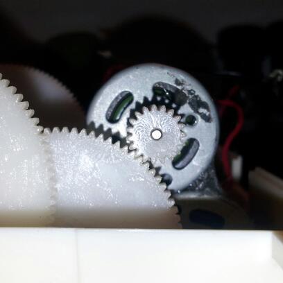
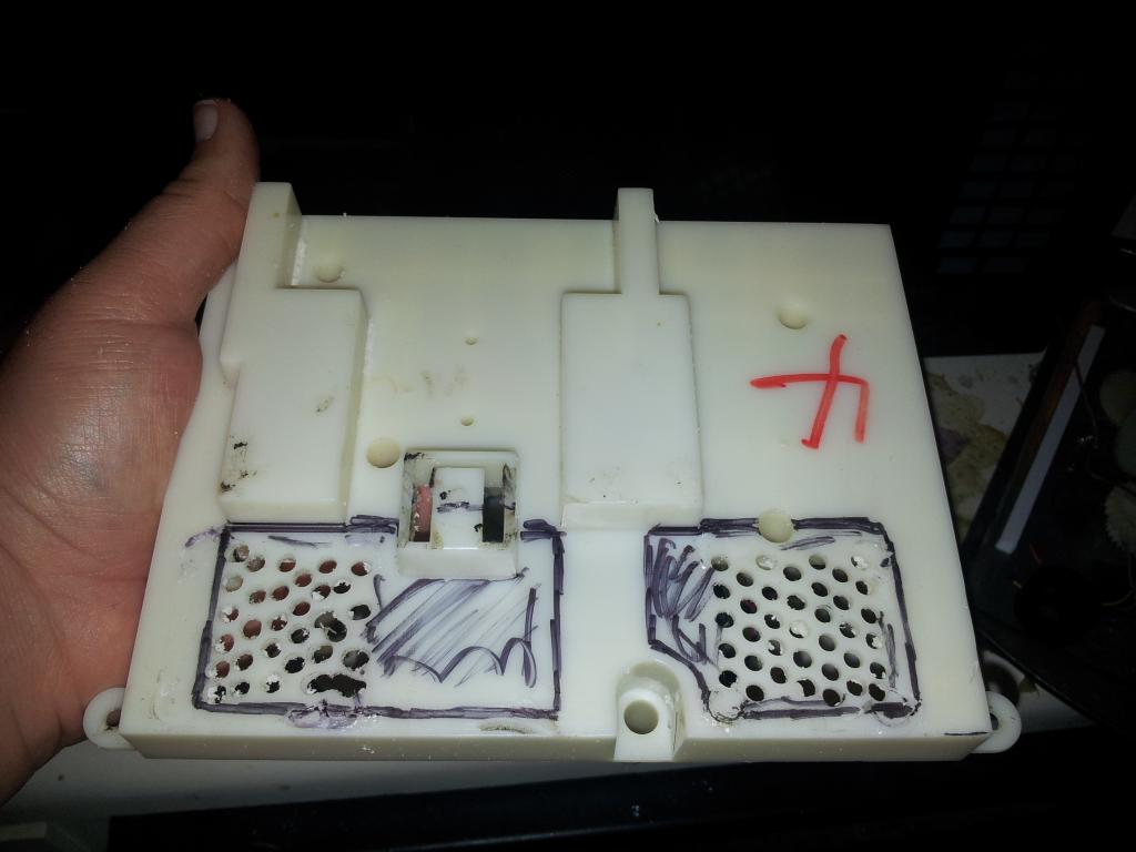
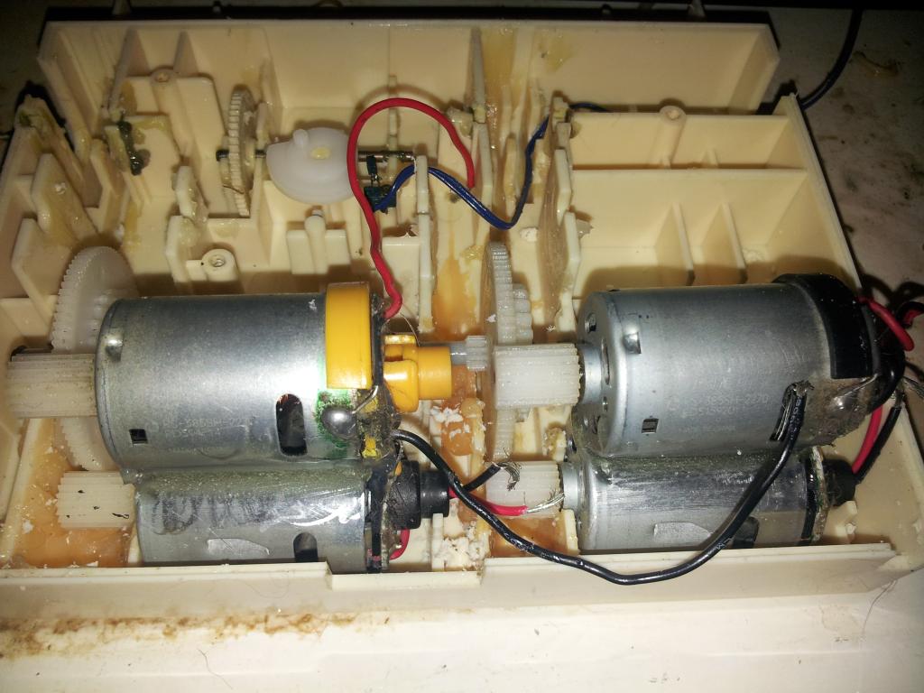
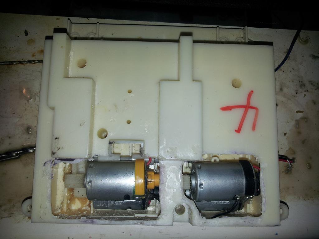
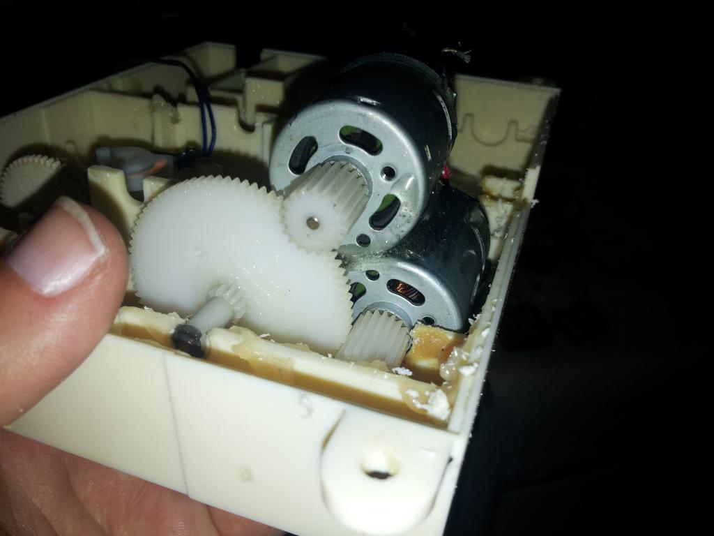
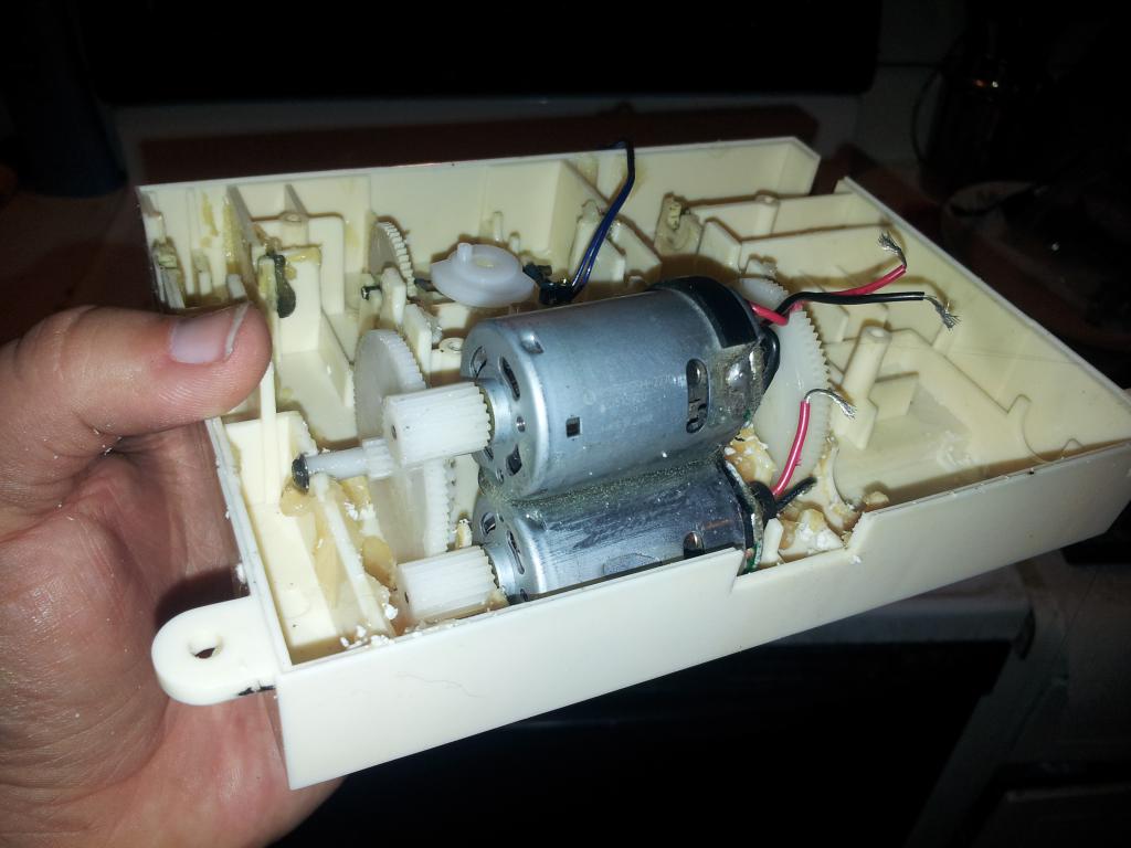
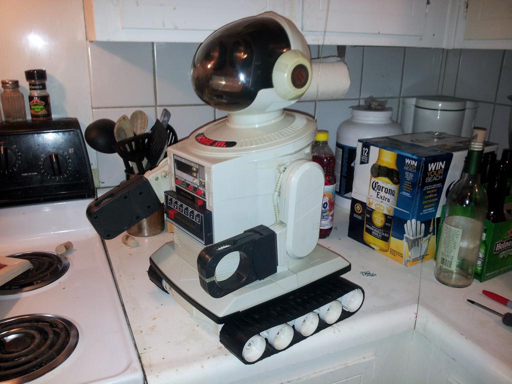
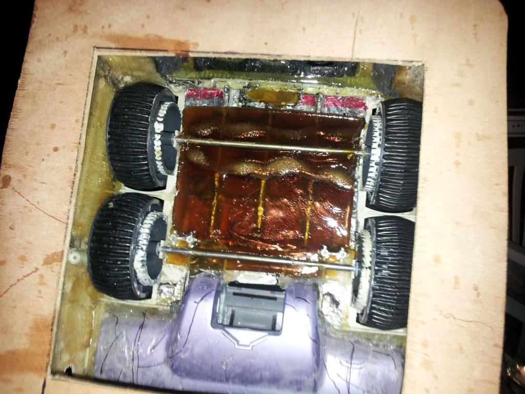
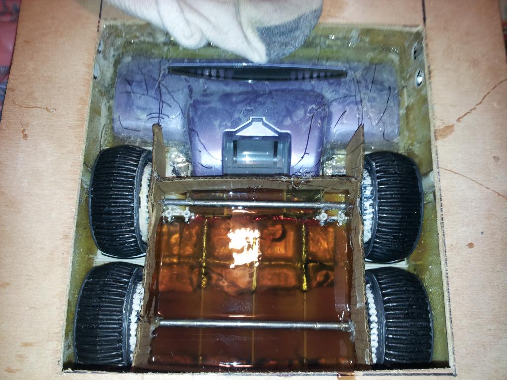
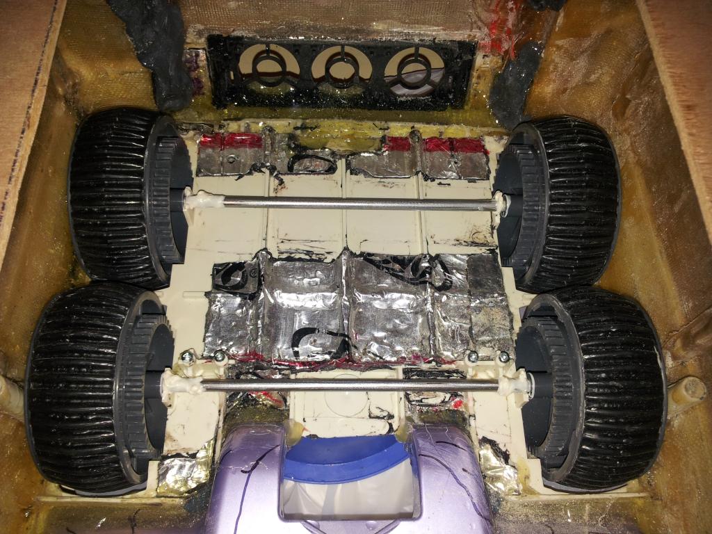
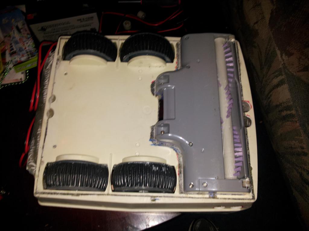
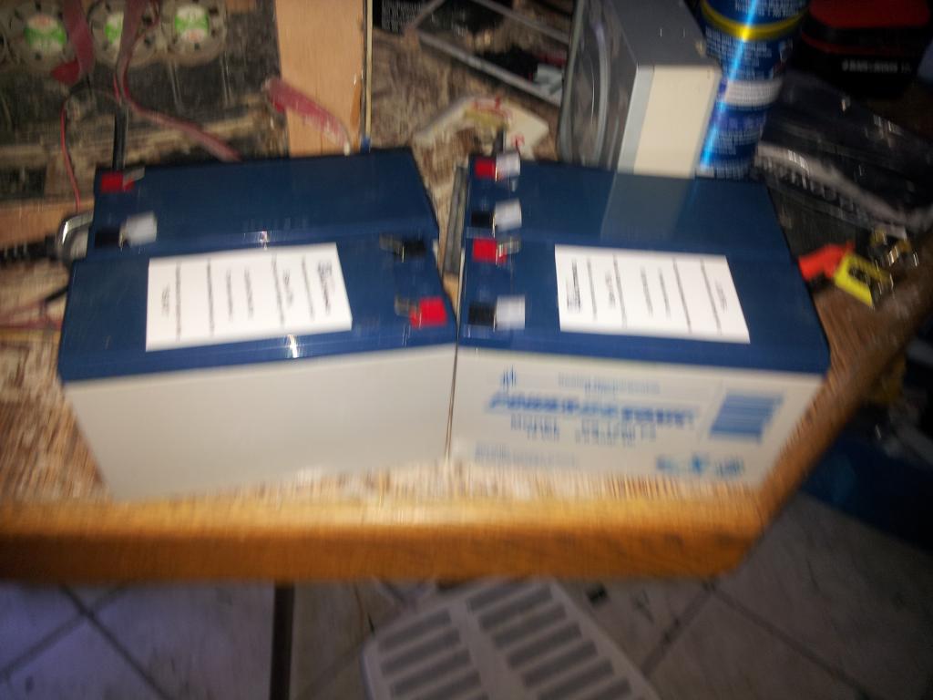
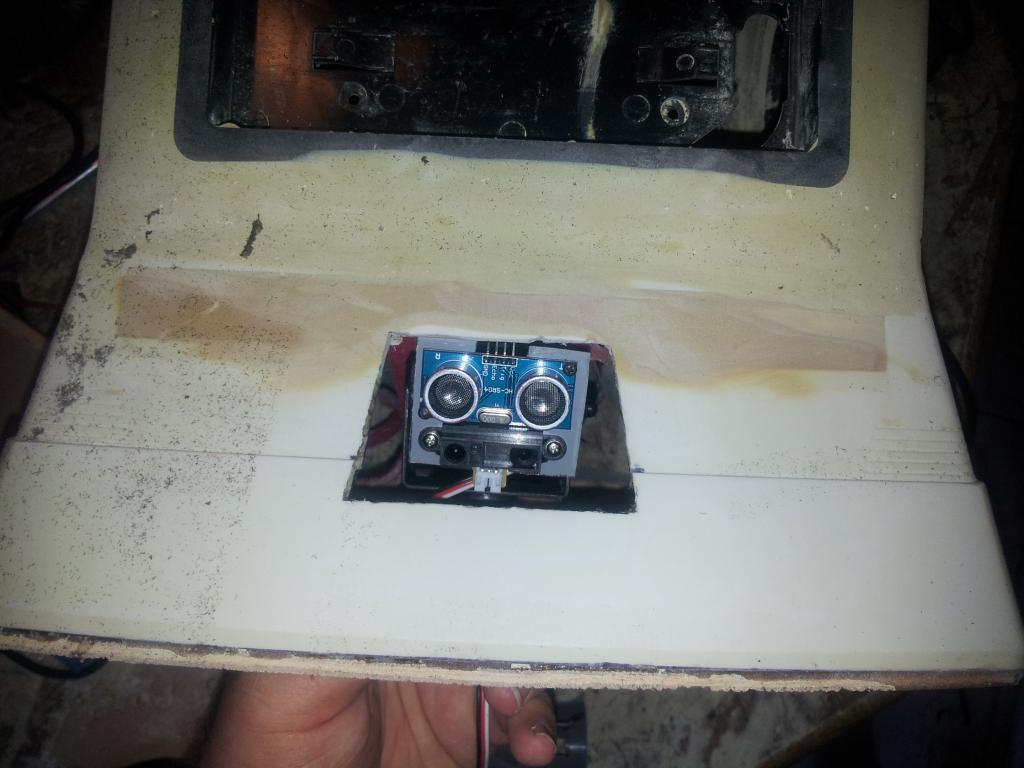
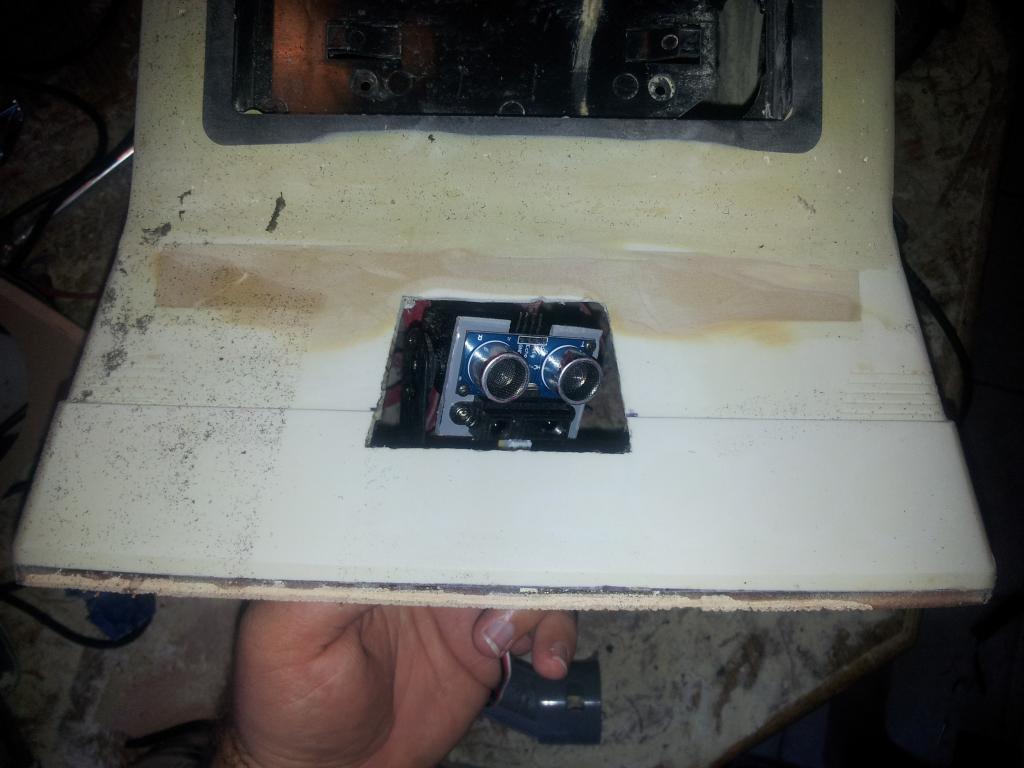
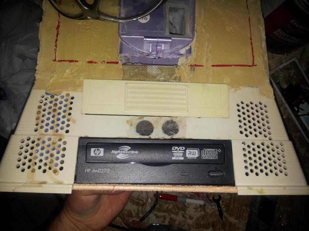
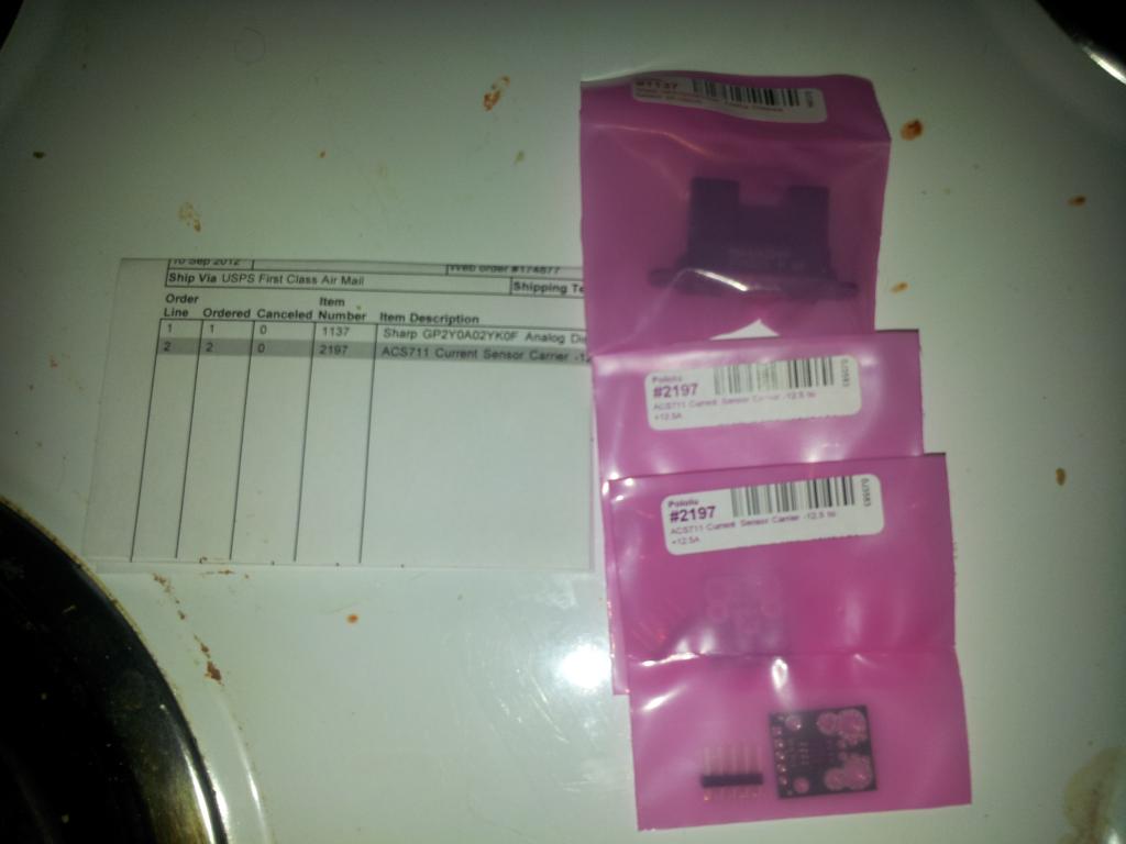
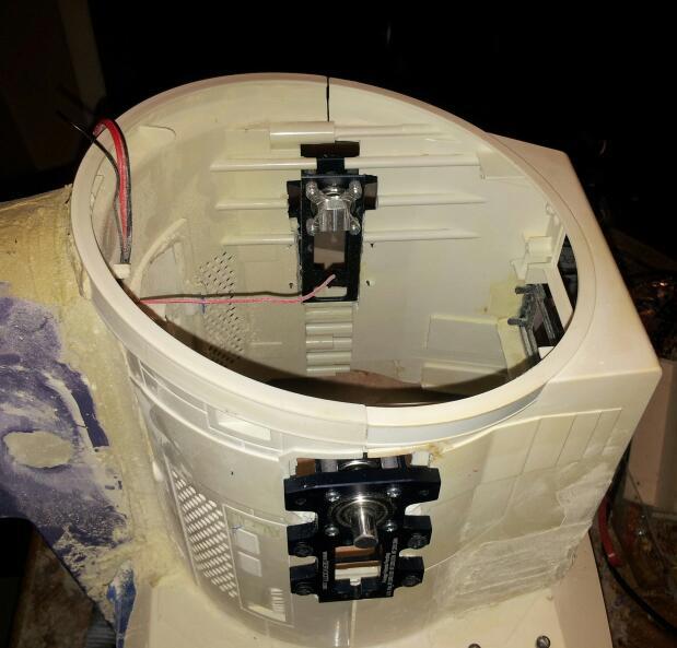
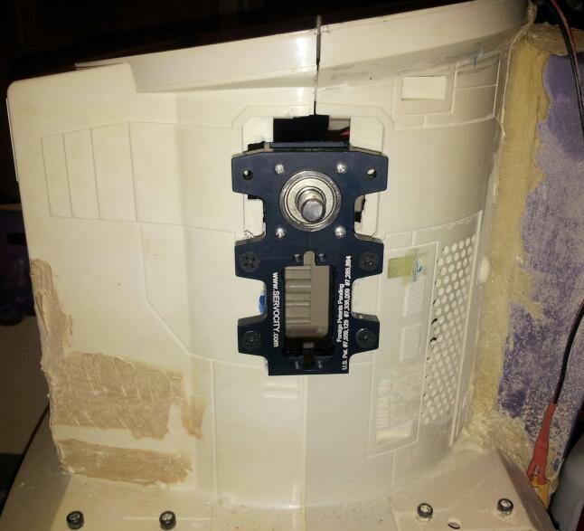
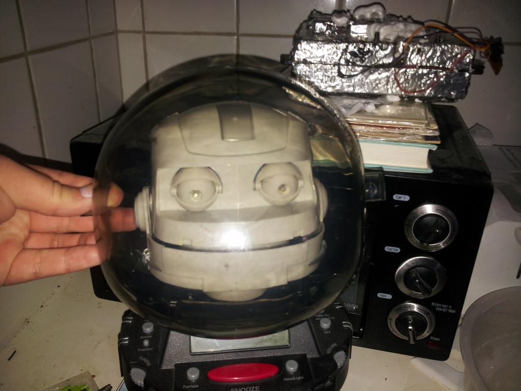
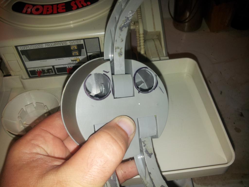
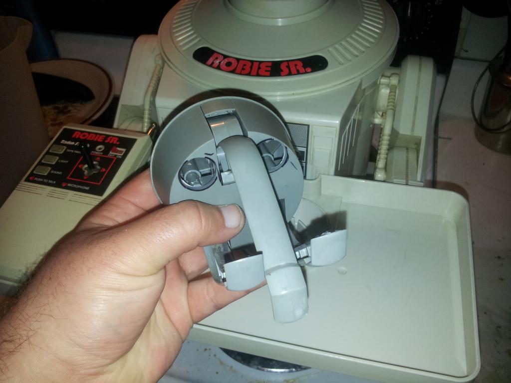
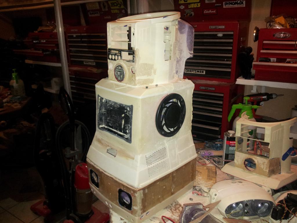
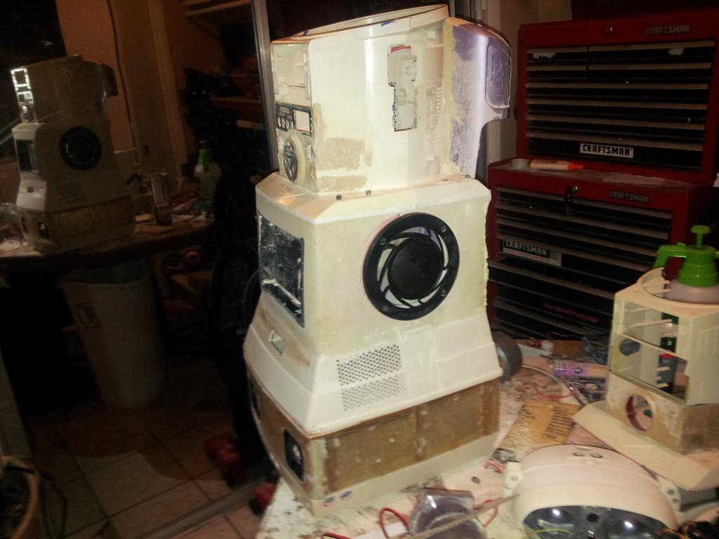
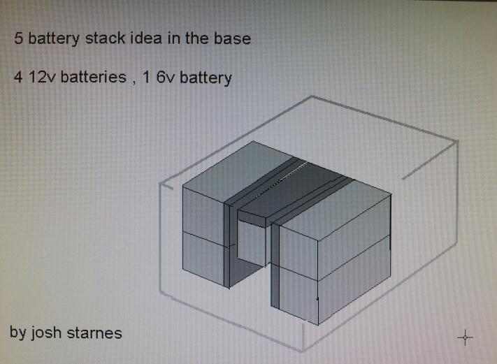
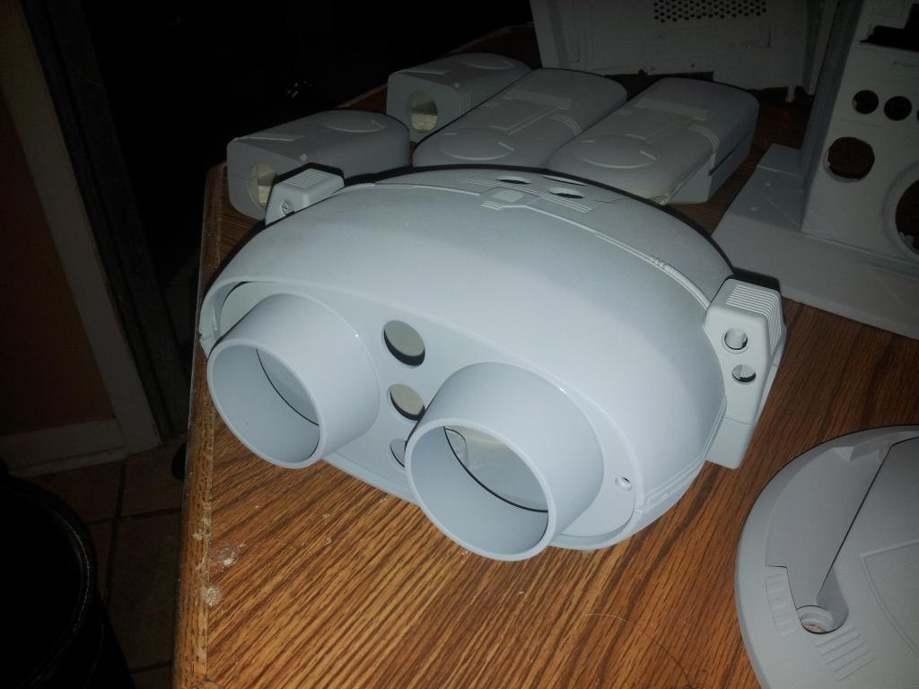
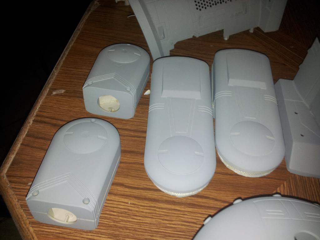
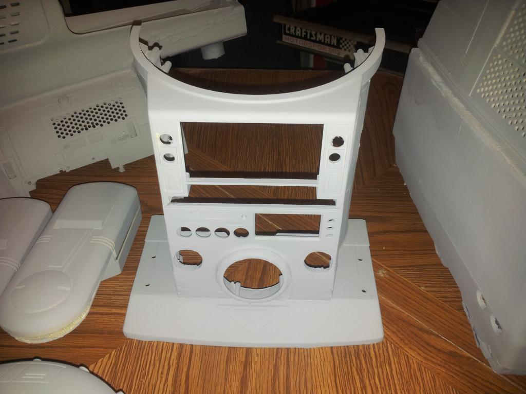
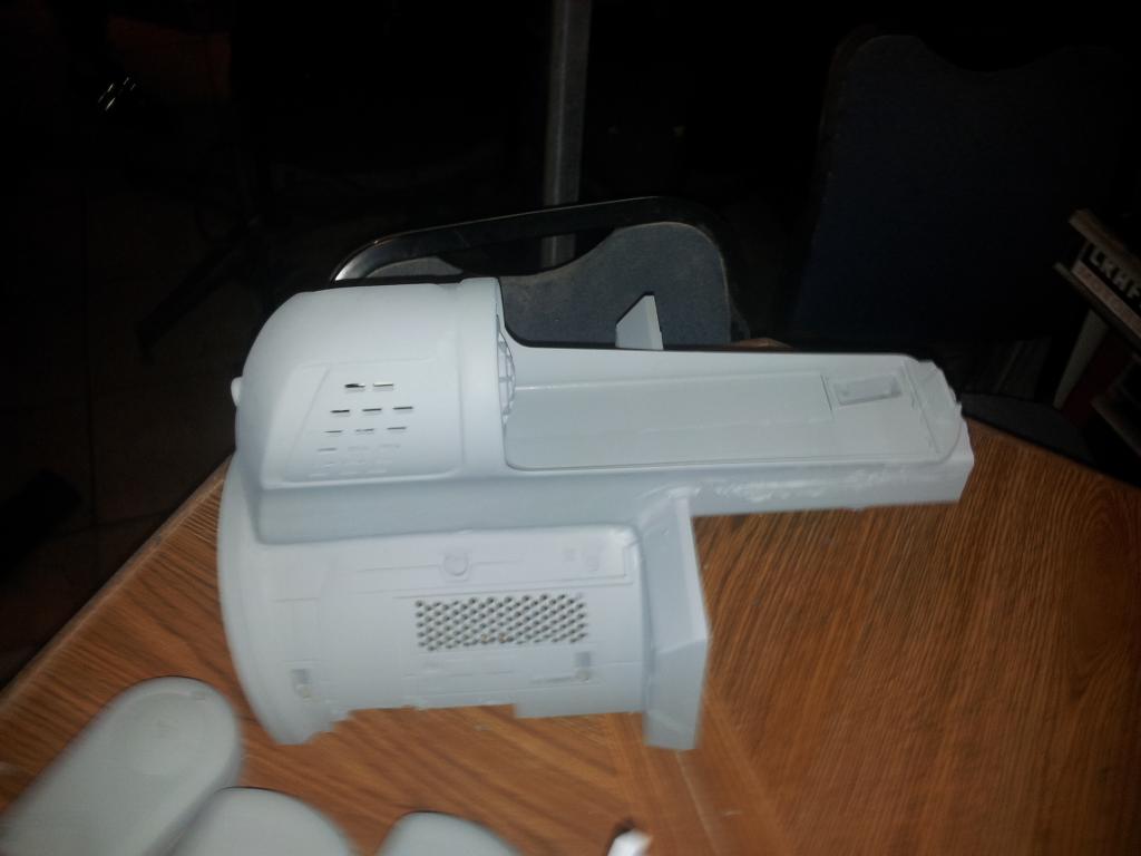
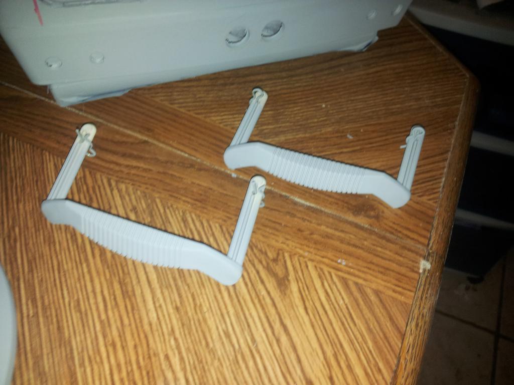
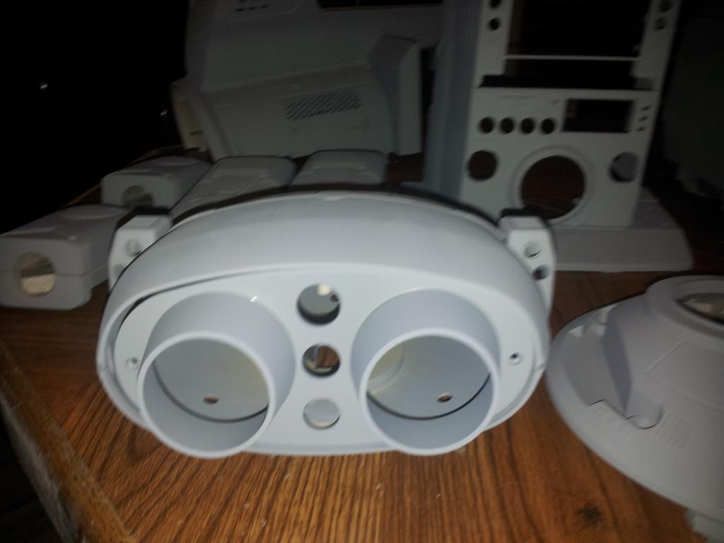
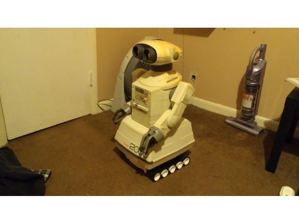
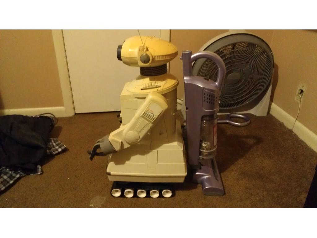
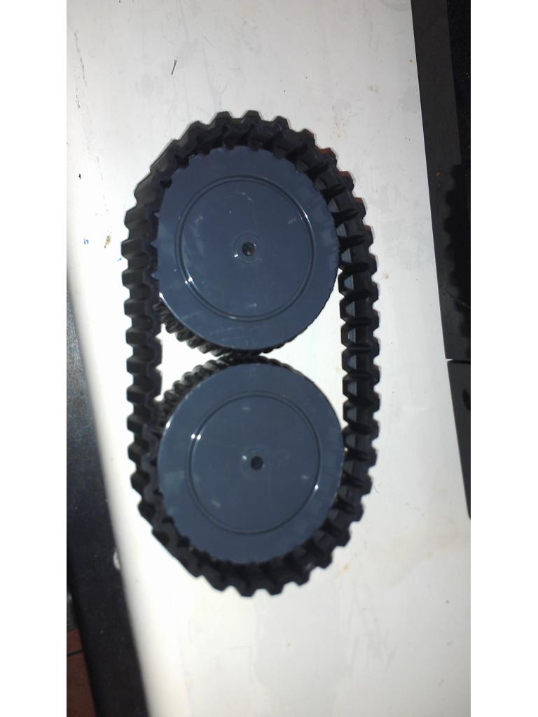
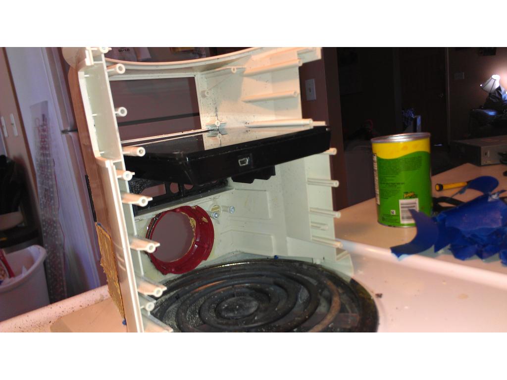
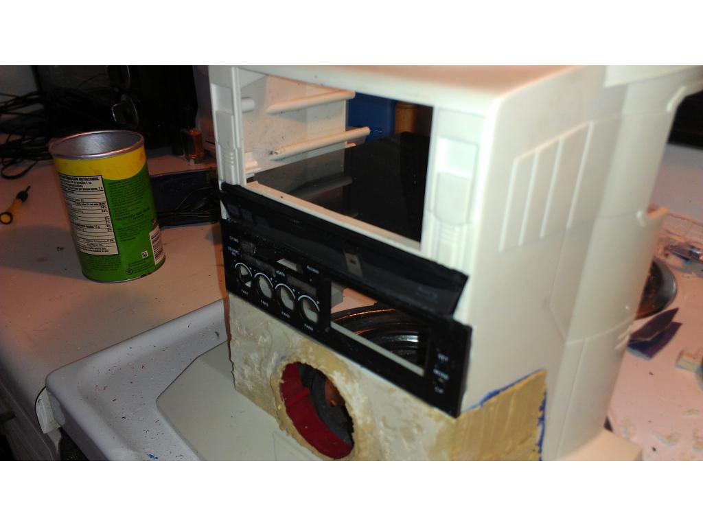
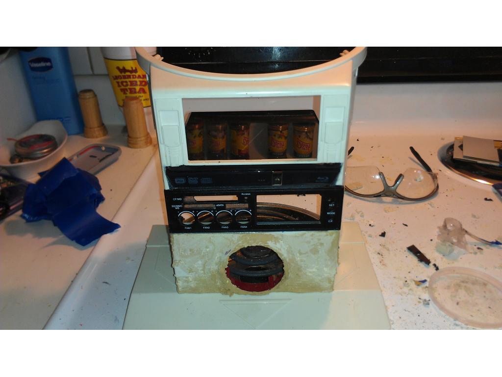
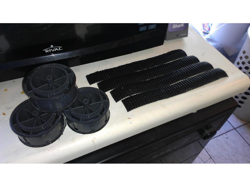
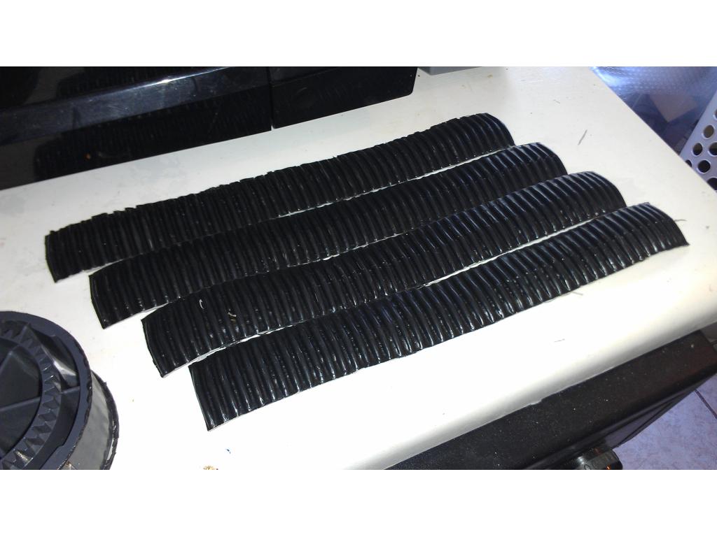
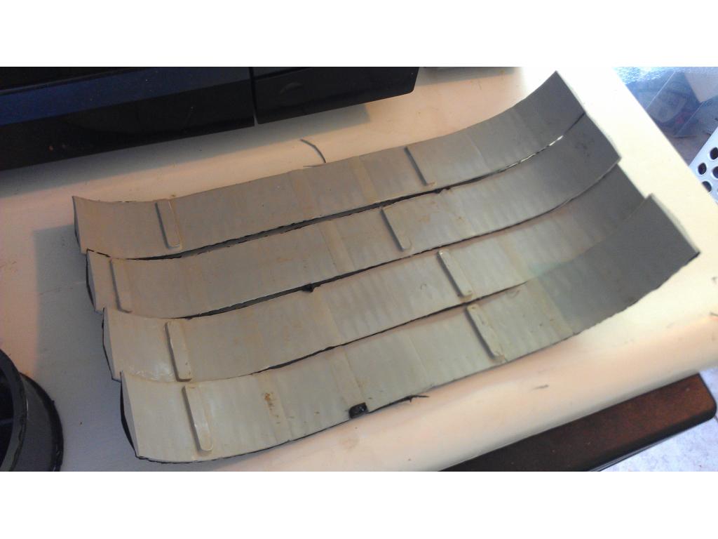
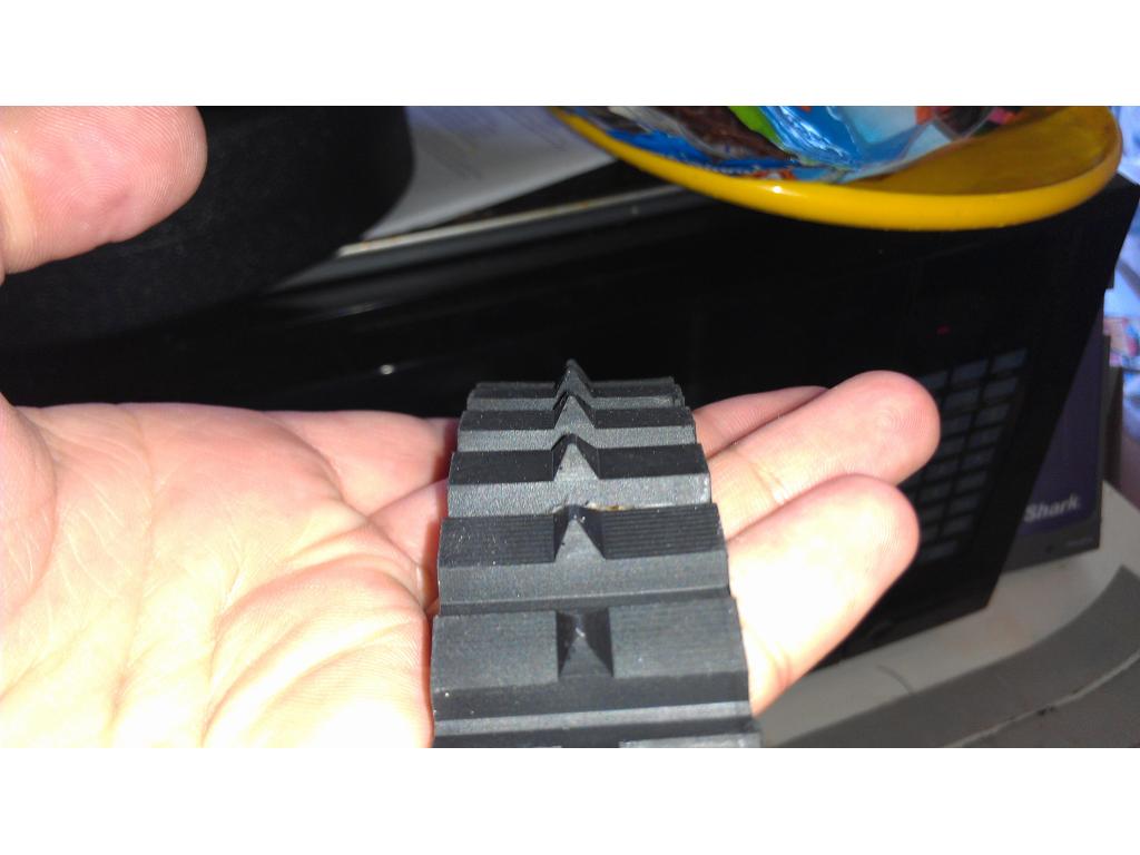
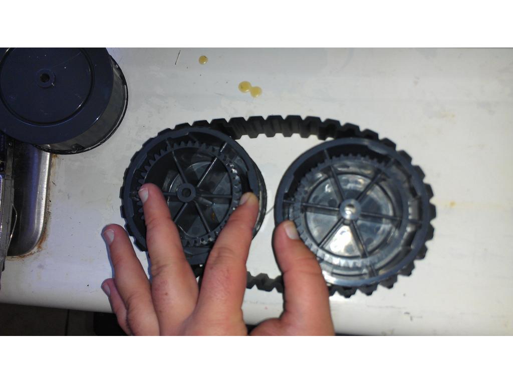
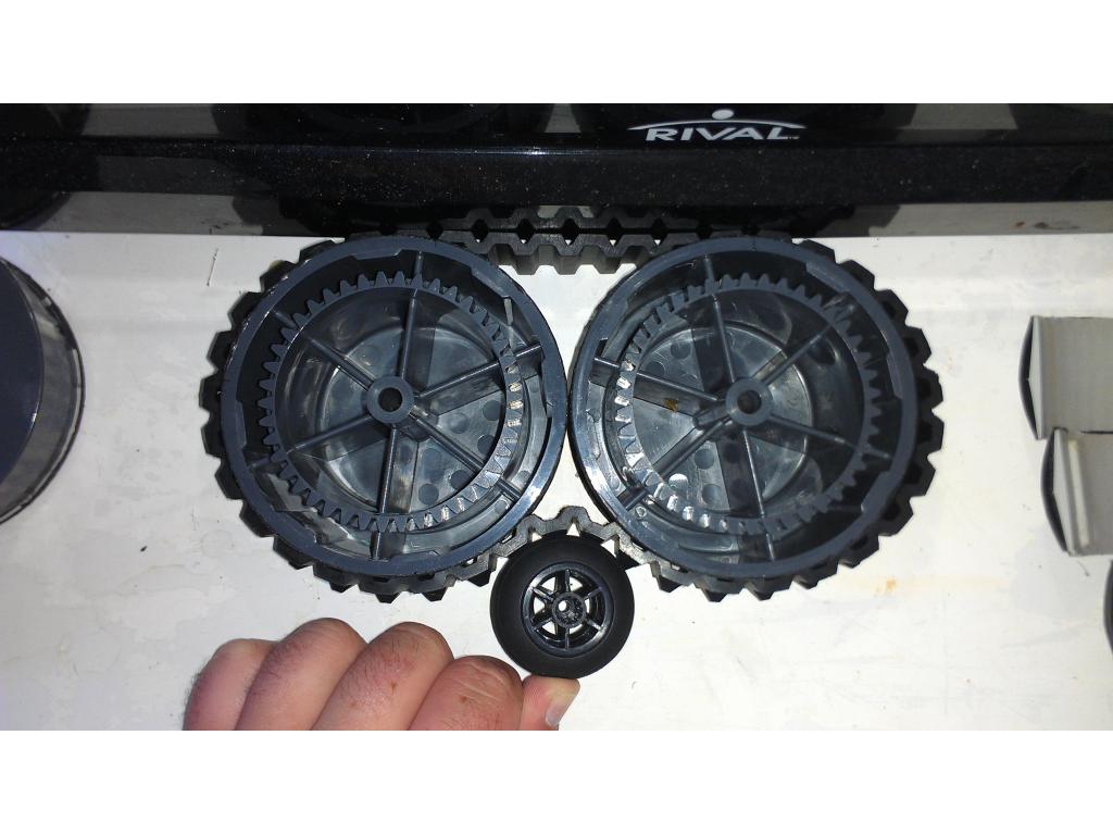
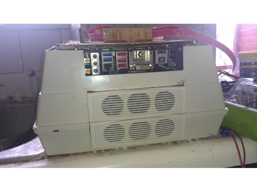
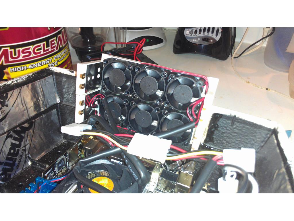
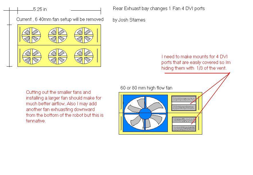
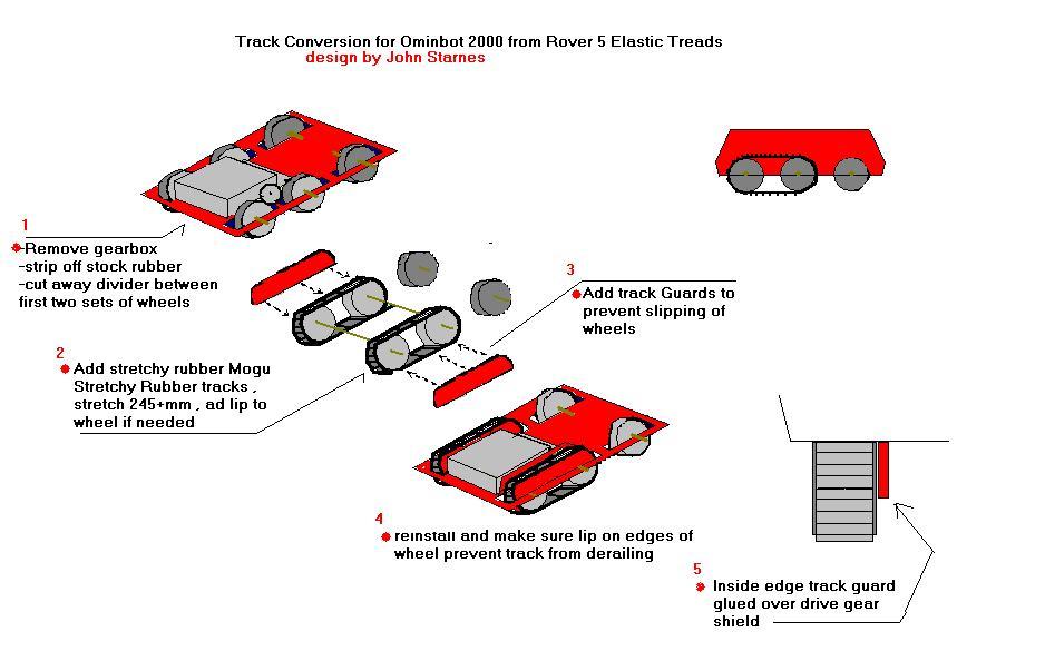
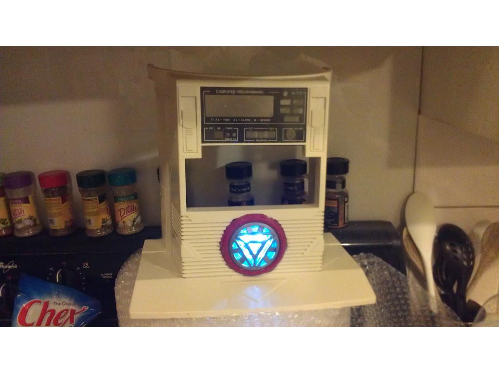
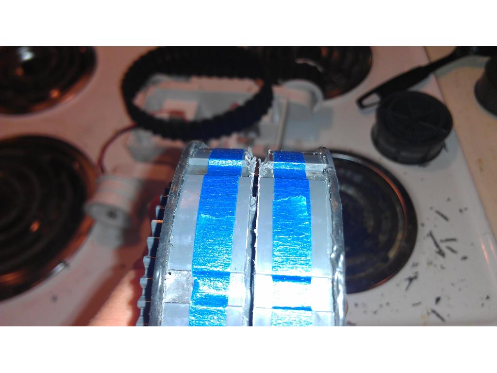
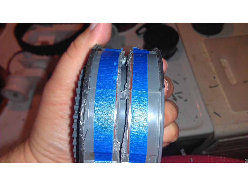
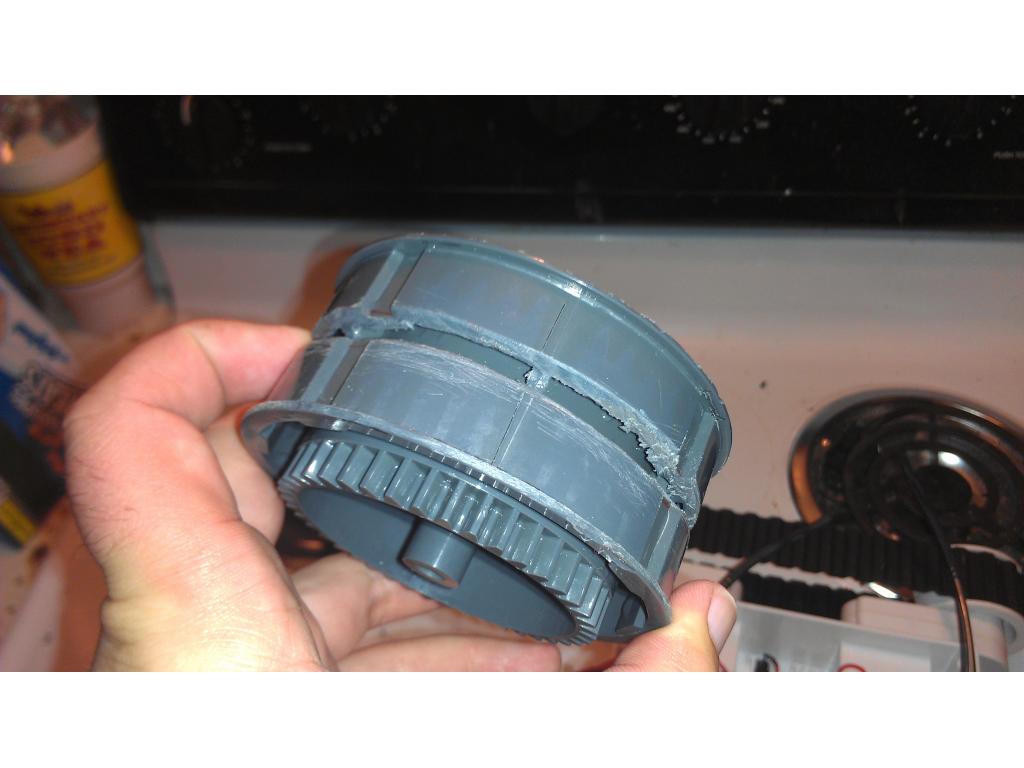
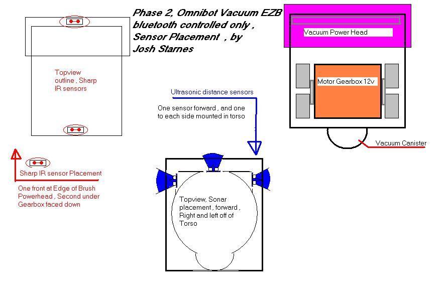
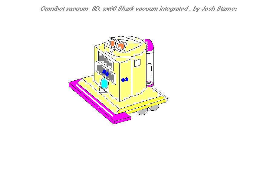
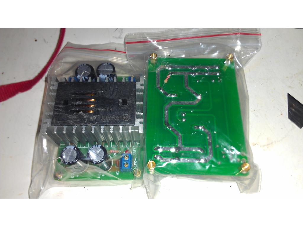
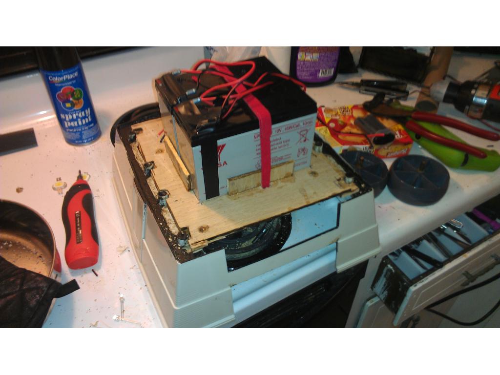
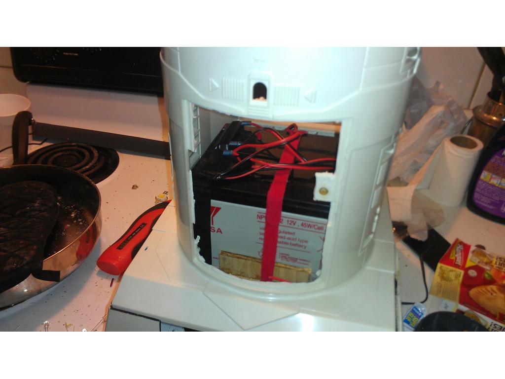
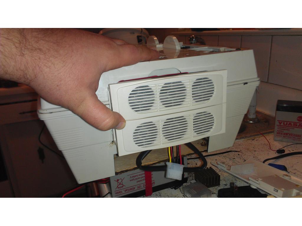
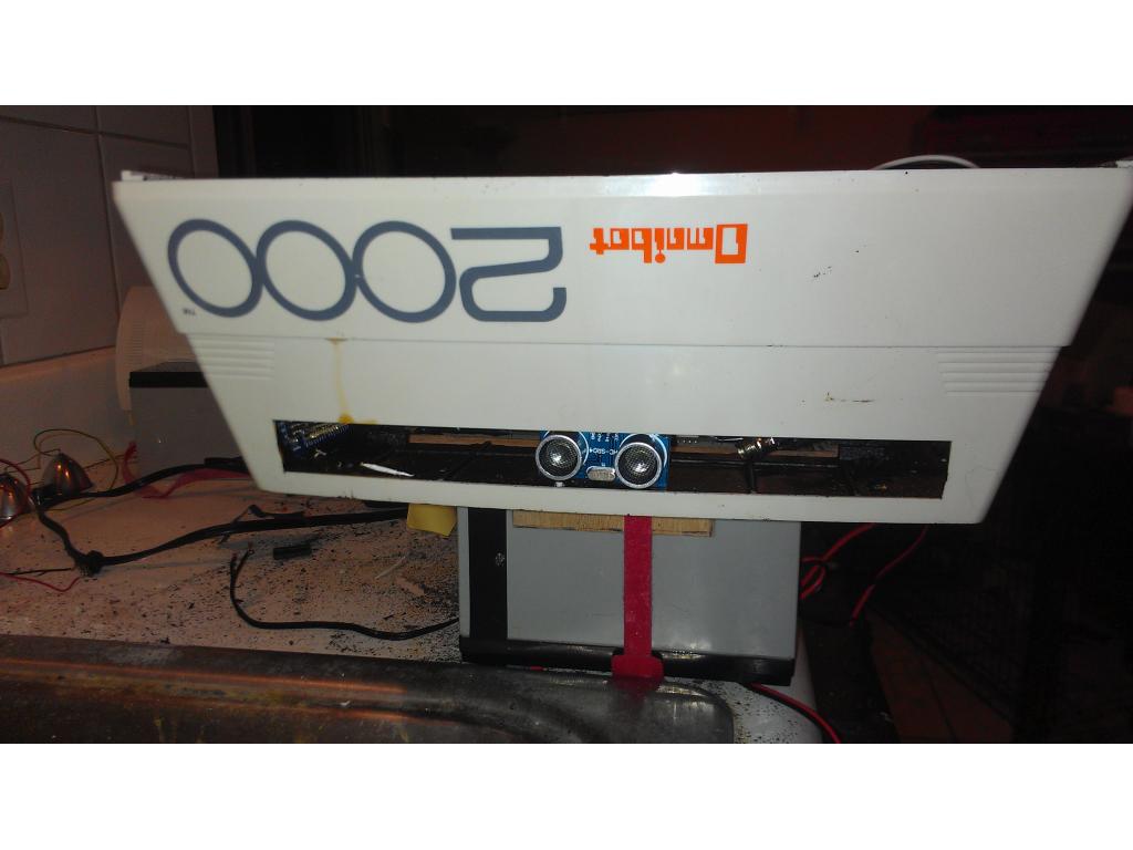
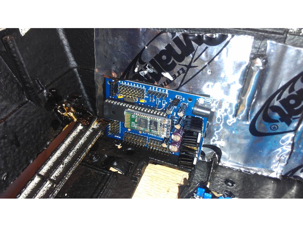
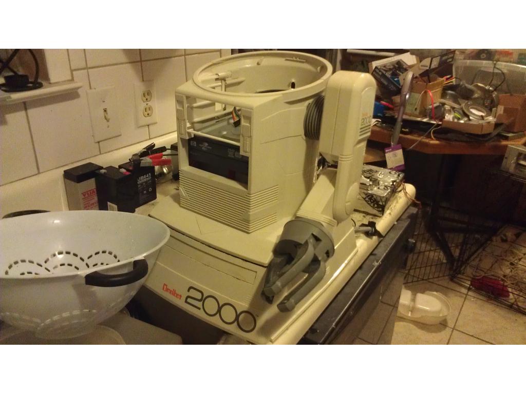
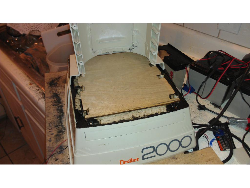
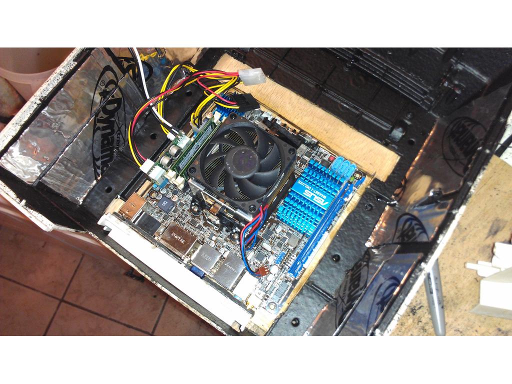
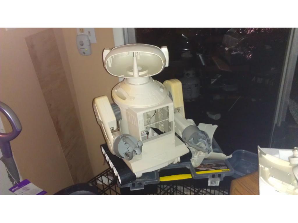
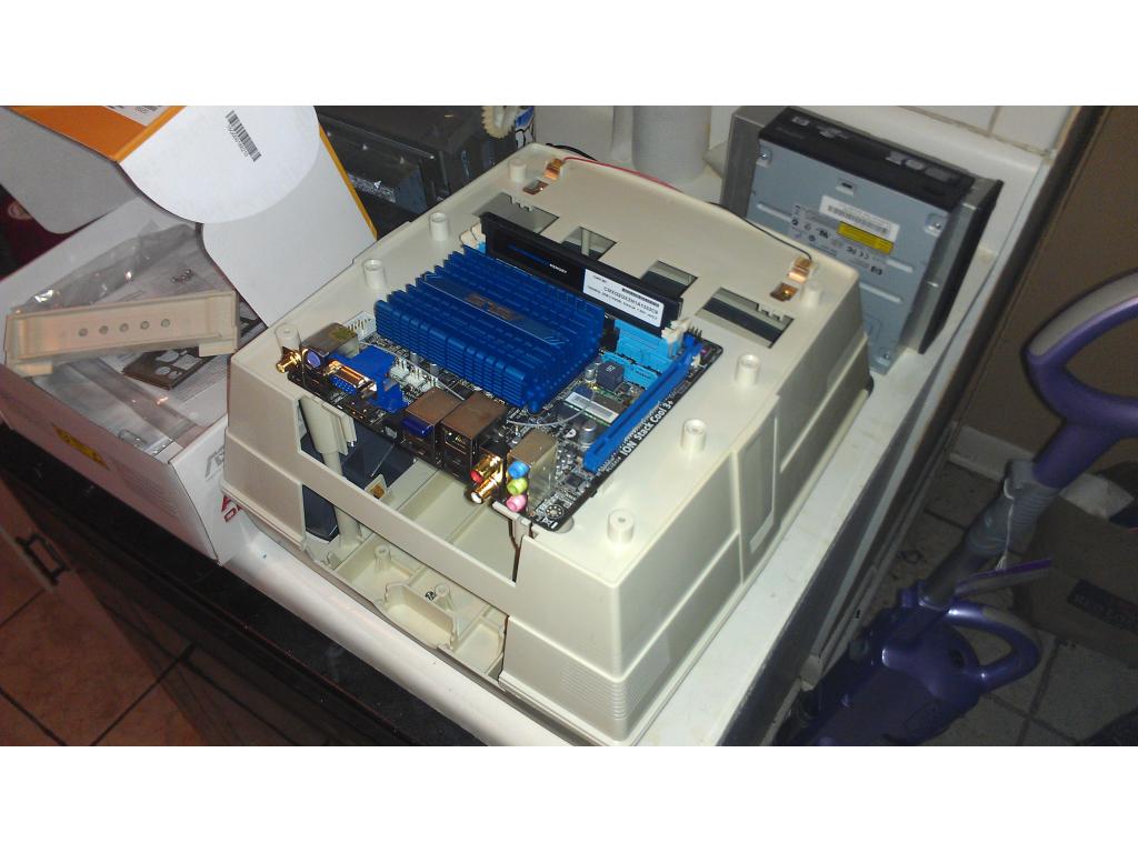
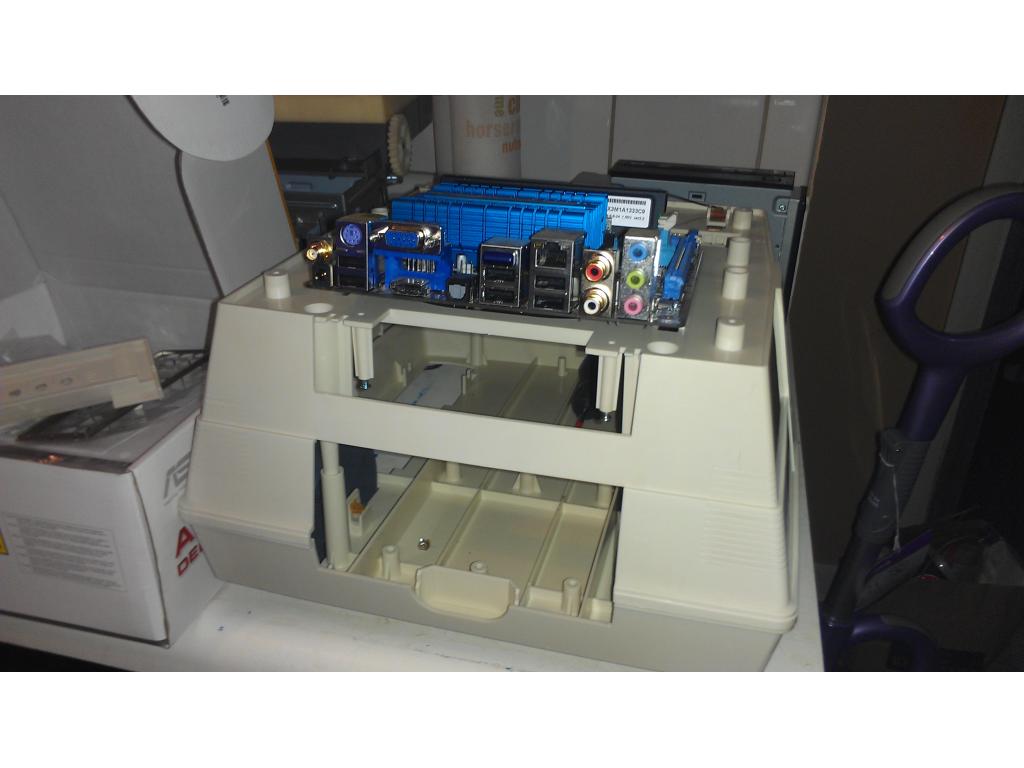
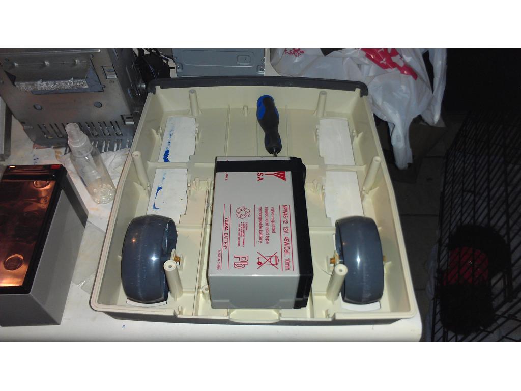
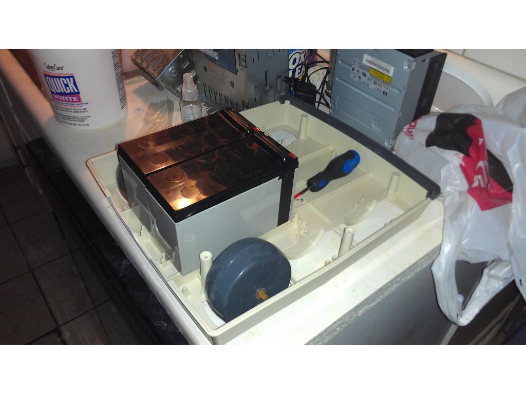
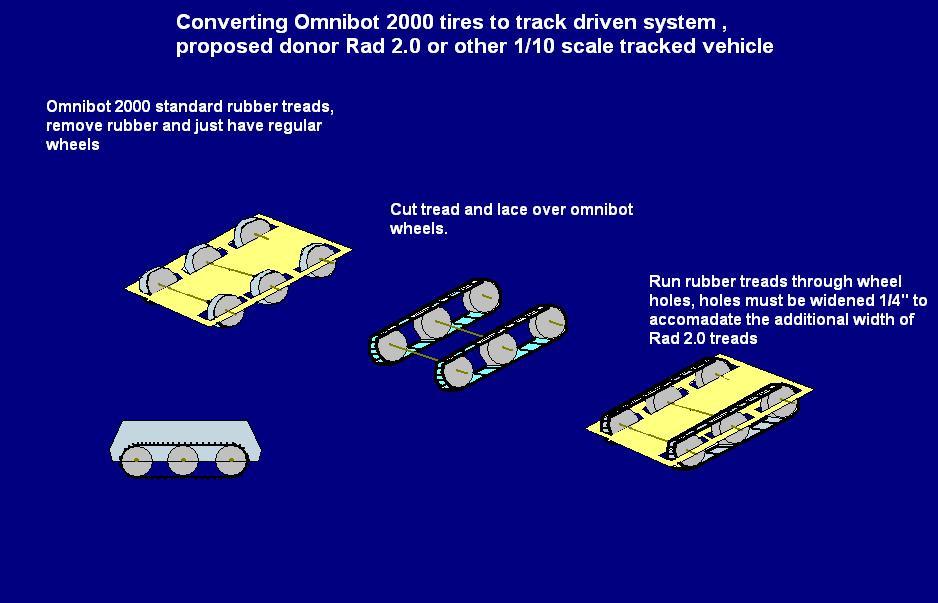
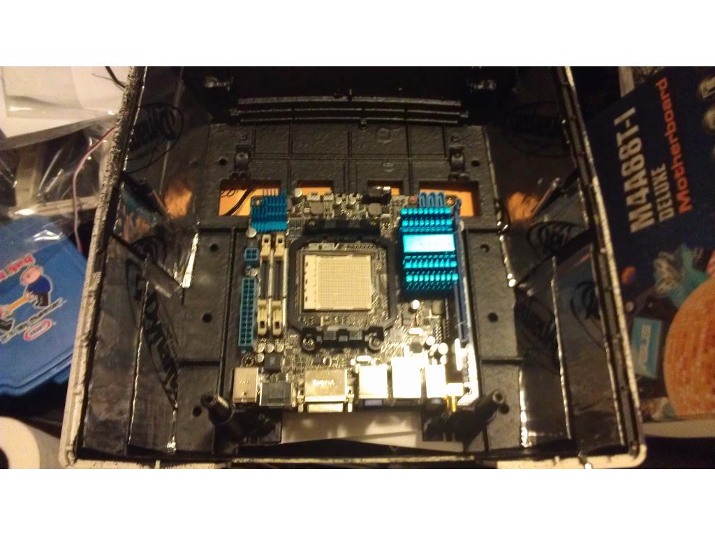
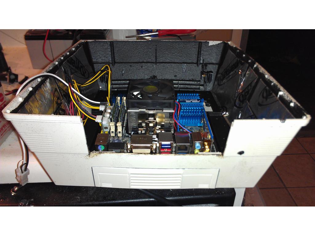
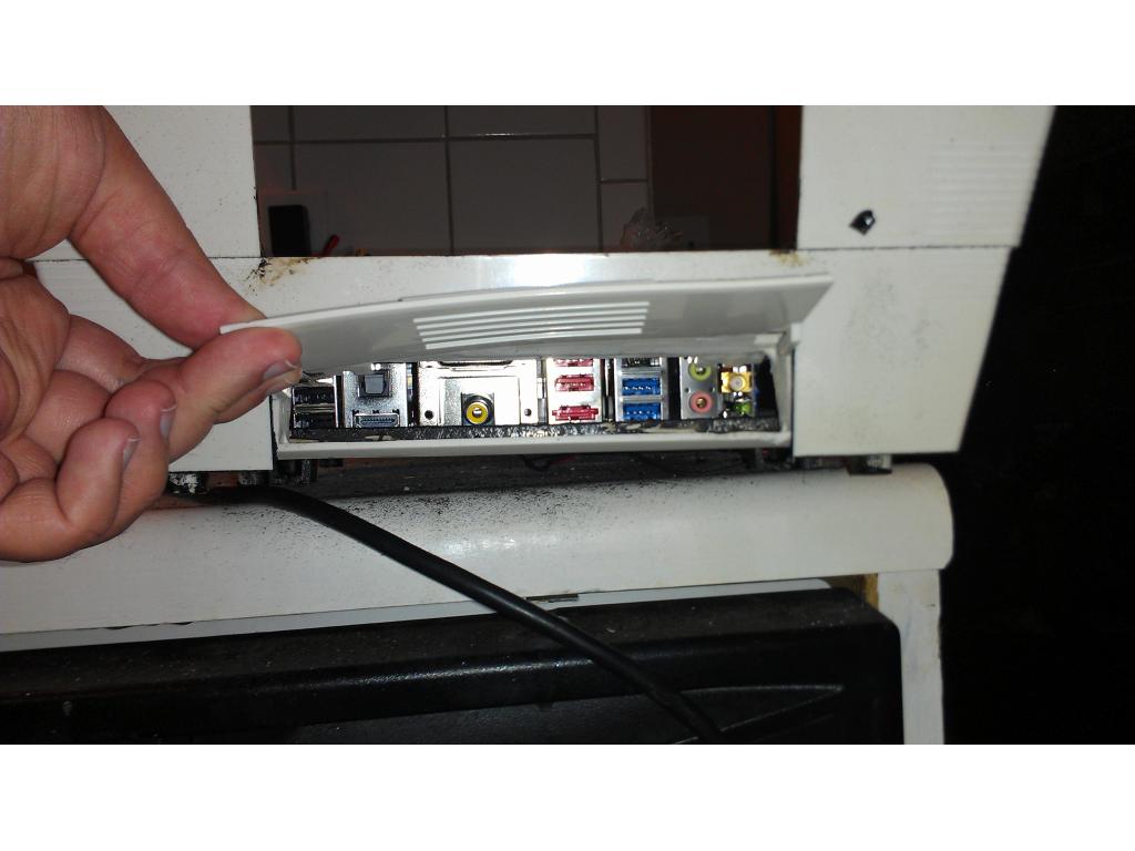
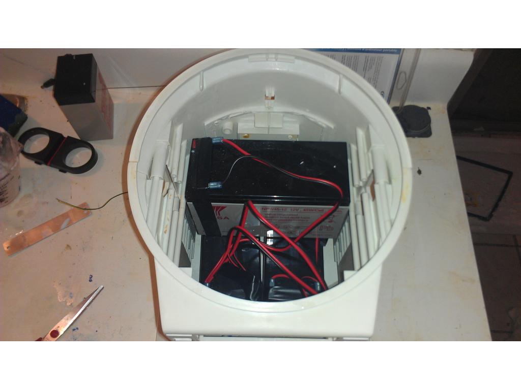
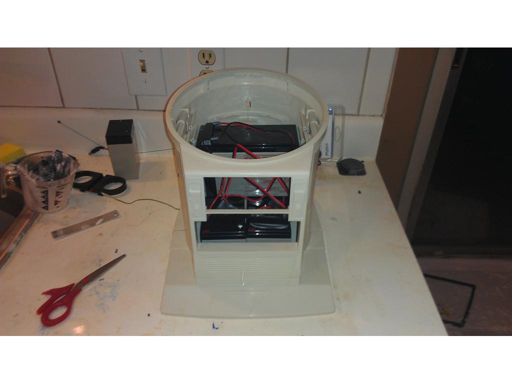
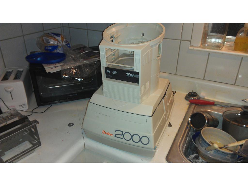
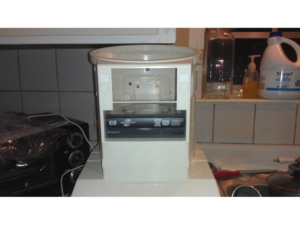
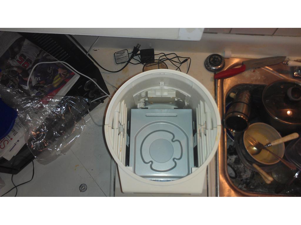
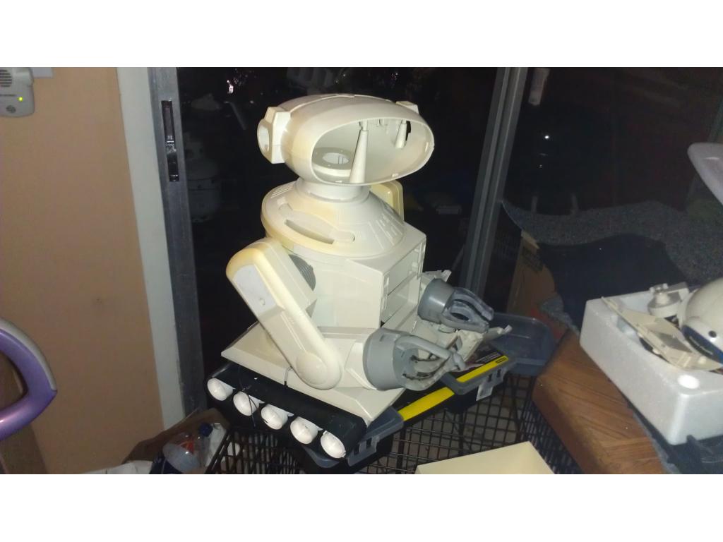
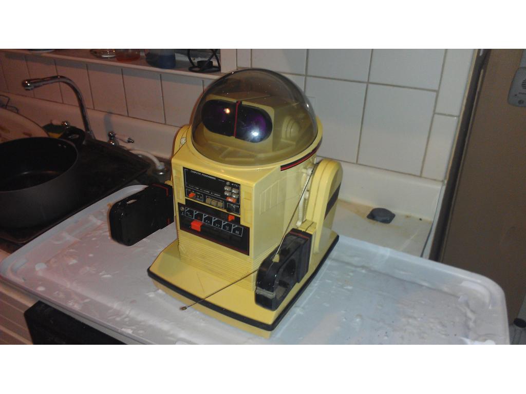
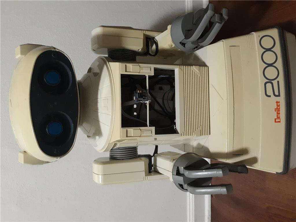
This project has evolved some , the basic rundown is I'm modding two Omnibots , one a regular the other a larger 2000 model. I will have two ezb kits , rad base idea was thrown out because of so much noise but could go back on the table if the omnibot drivetrain is too weak to pull it.

By jstarne1
— Last update
Discover more robots
Xuven's Project Atlas 1.0
Project Gizmo robot with head and arm movement, MP3-triggered personality; future onboard computer, chest touchscreen,...
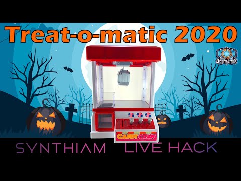
Jeremie's Treat-O-Matic 2020
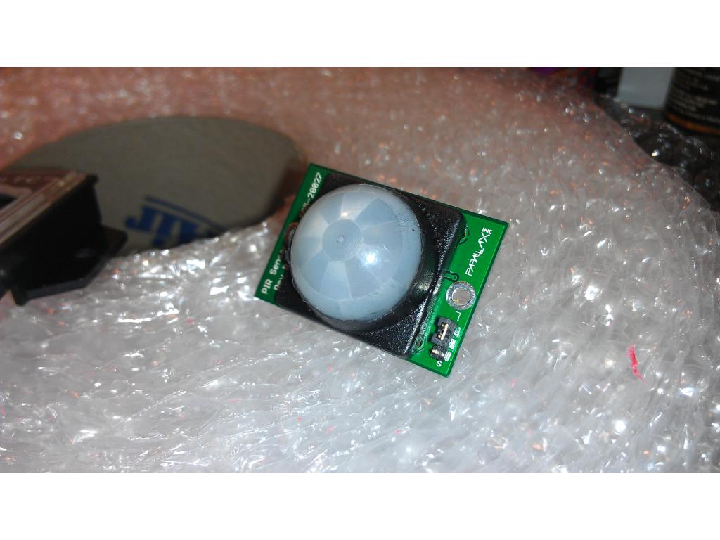
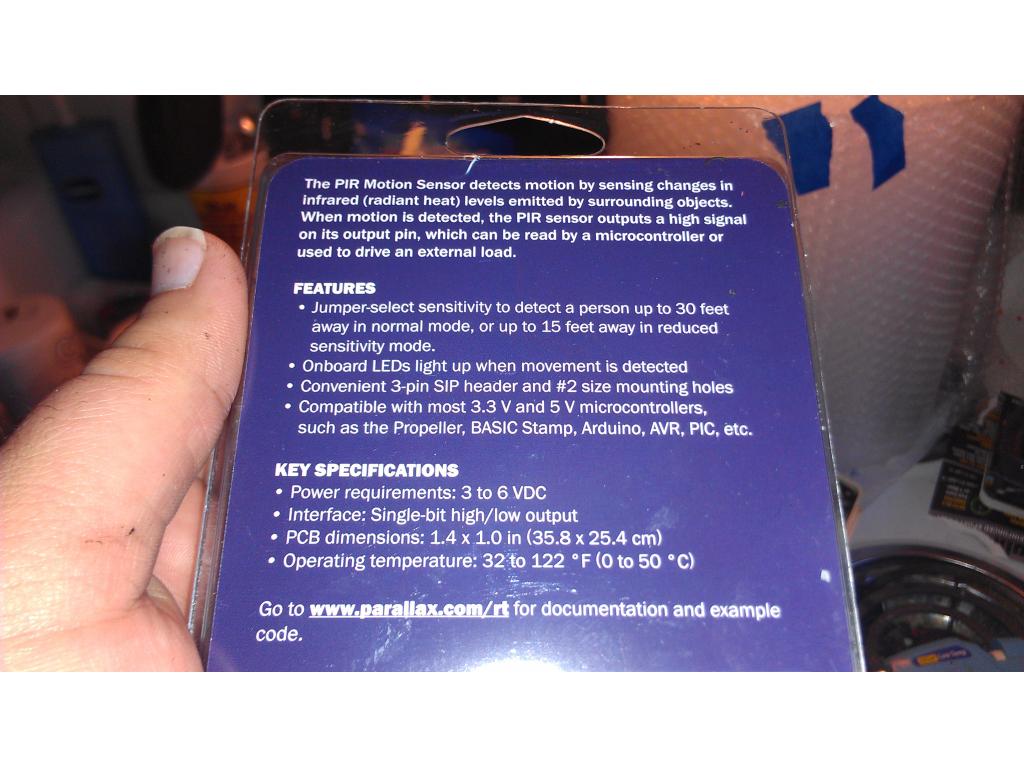
Convert a claw-style candy machine into a contactless Halloween dispenser with Atomic Pi, Arduino EZB, camera, PIR,...

Rickymahk2013's Mark 1 Robot
Develop robots with Synthiam, build the Mark 1 DIY robot, publish a DIY book and showcase projects at international...

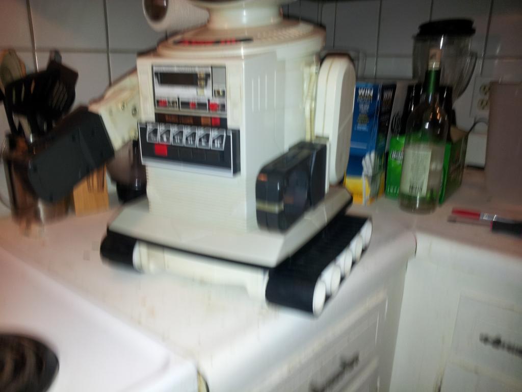
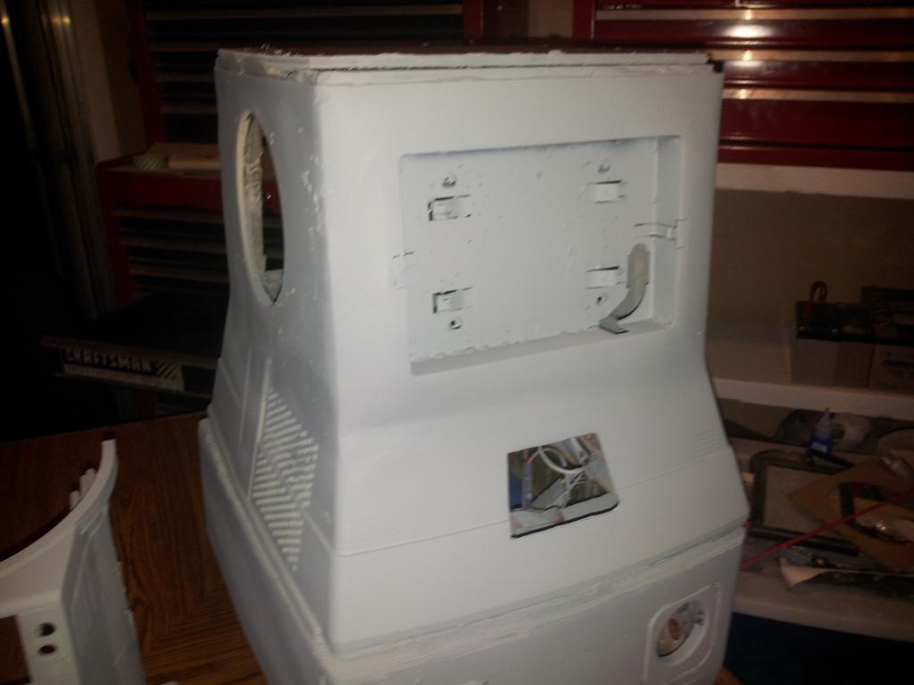
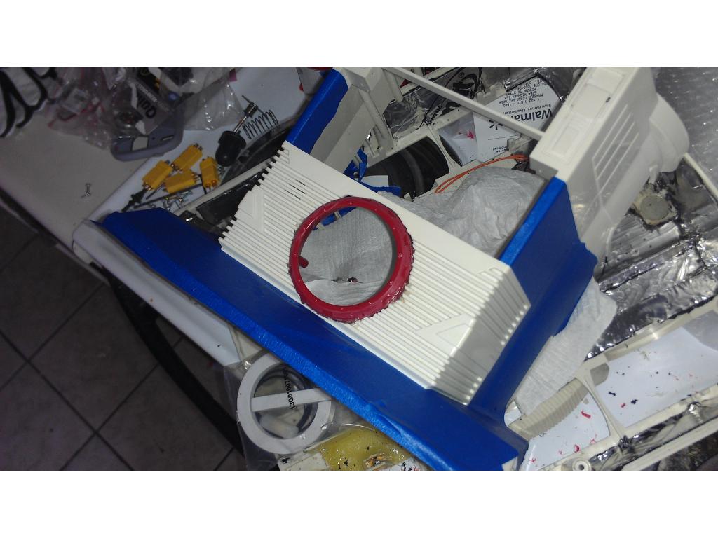
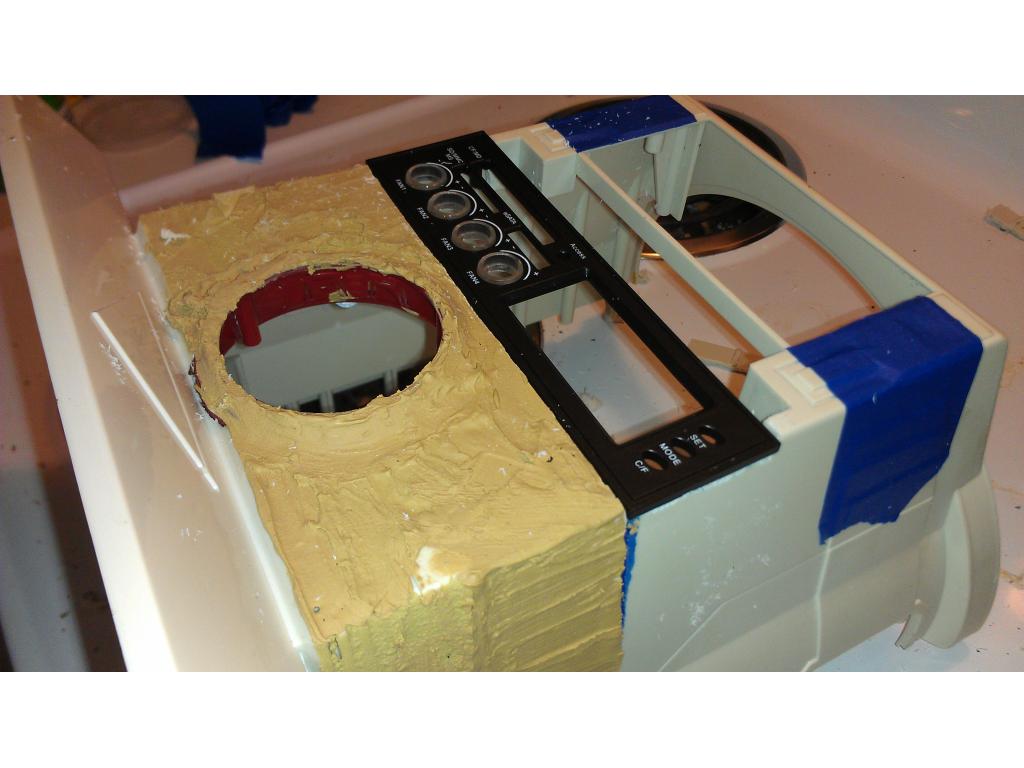
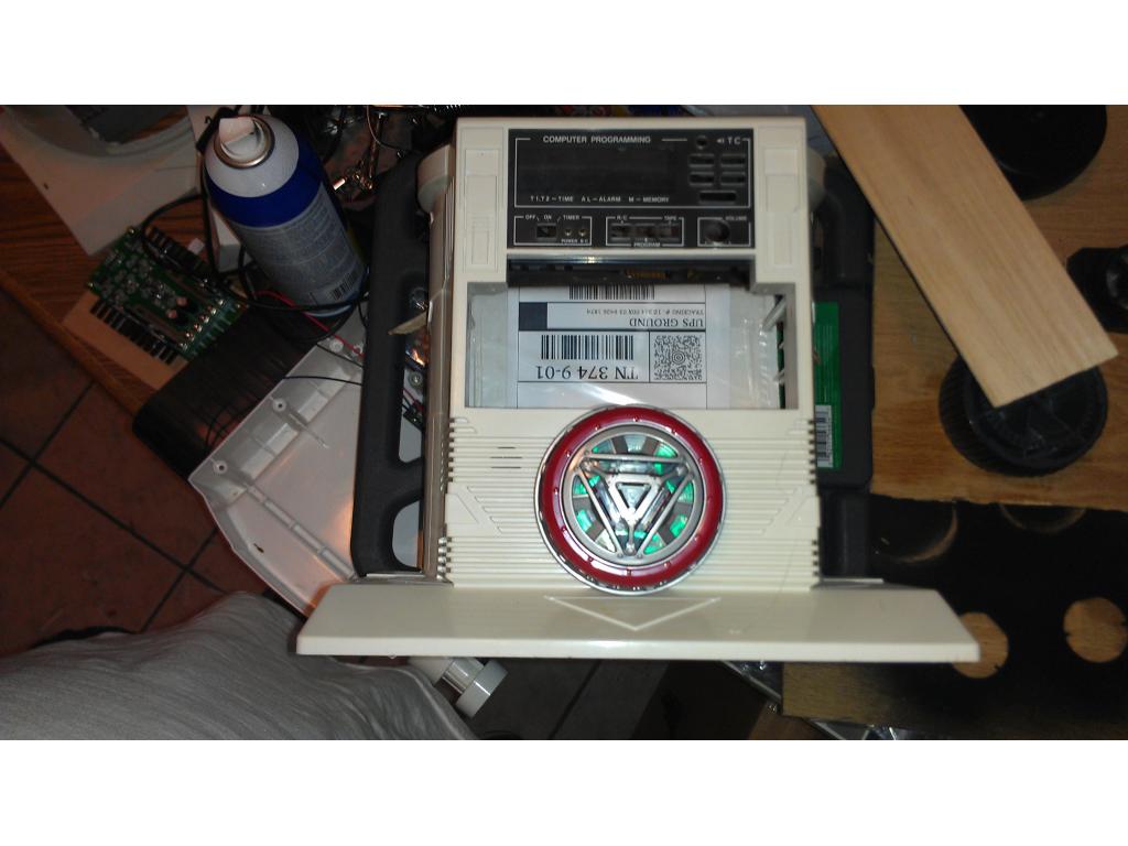
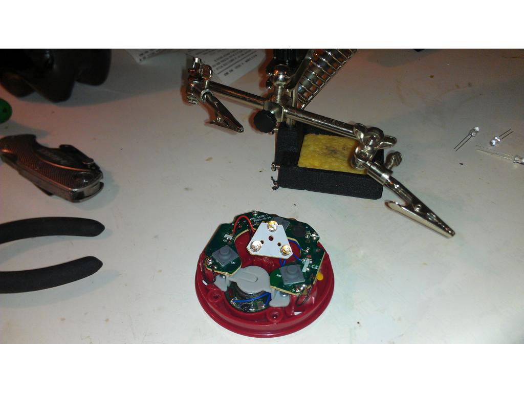
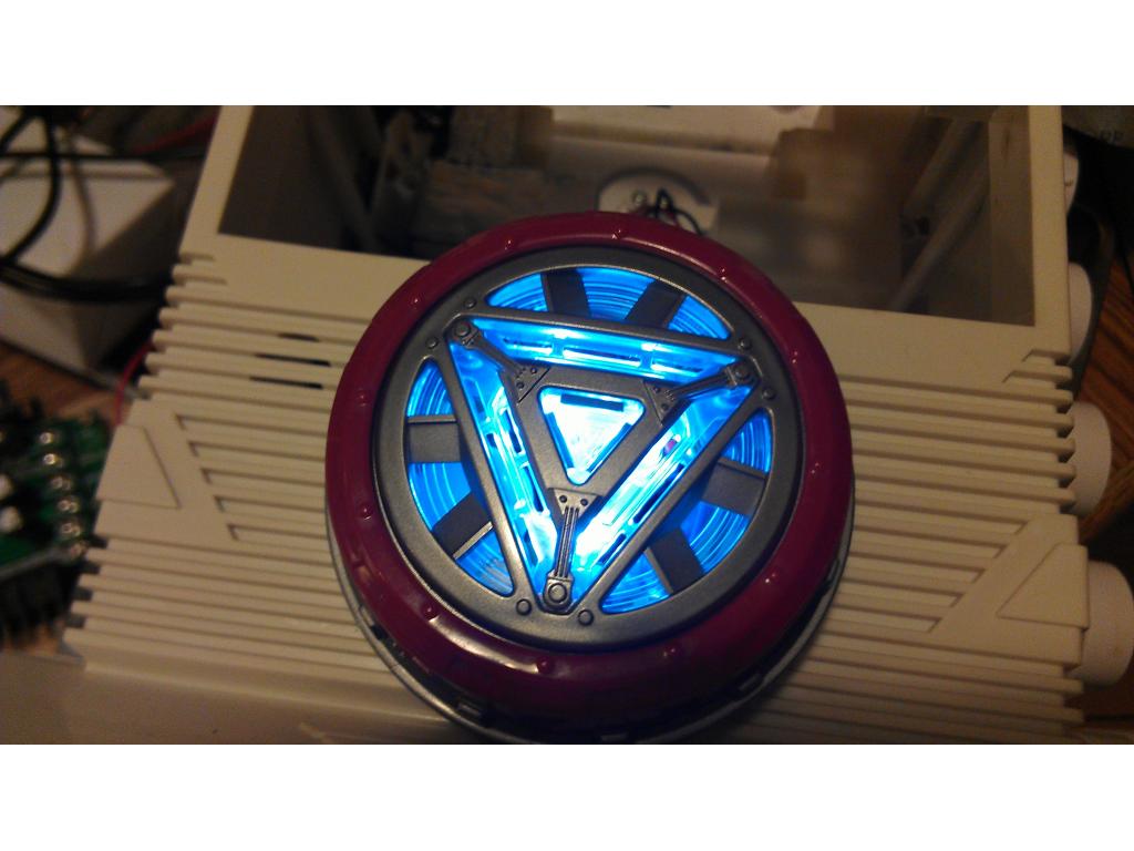
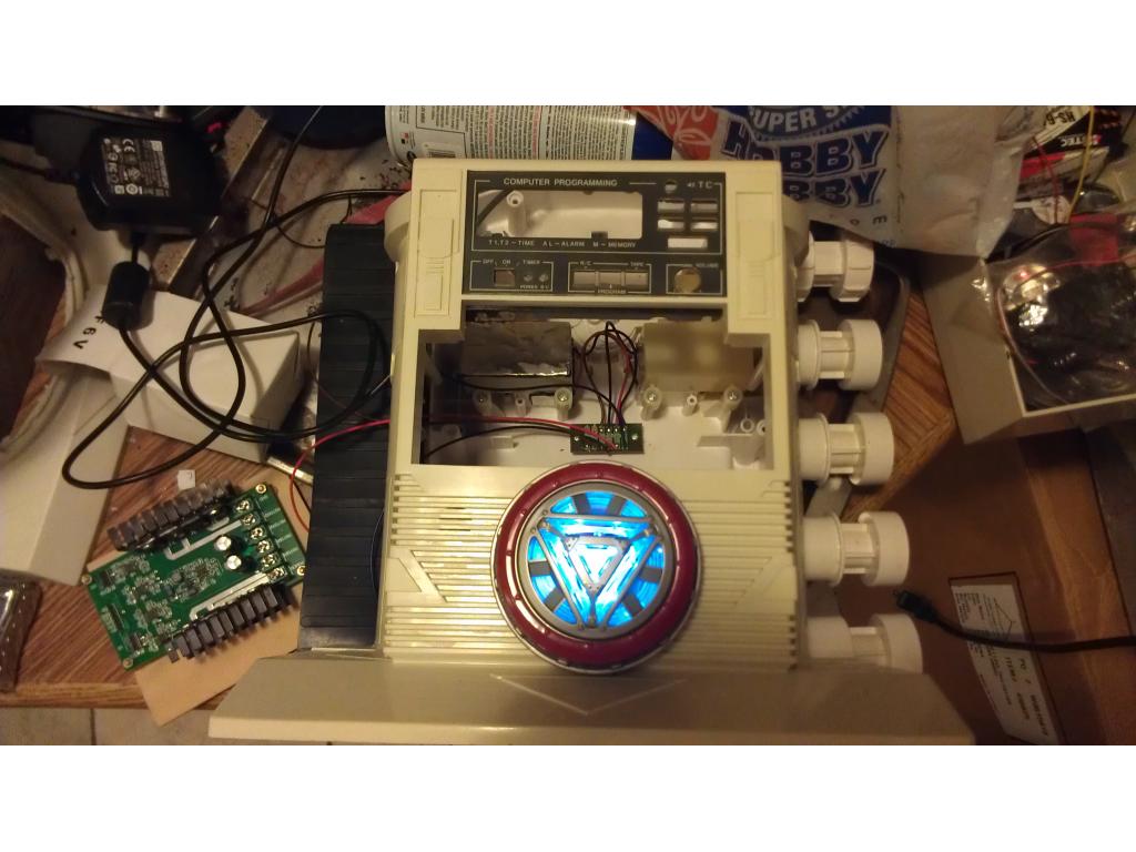
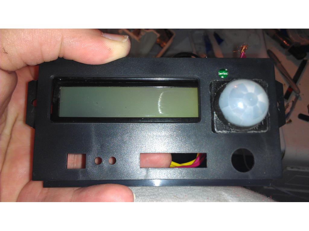
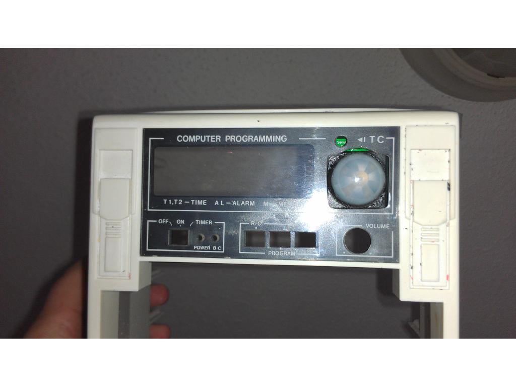
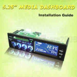
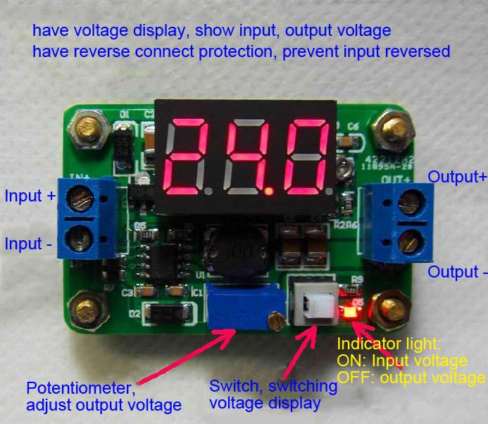
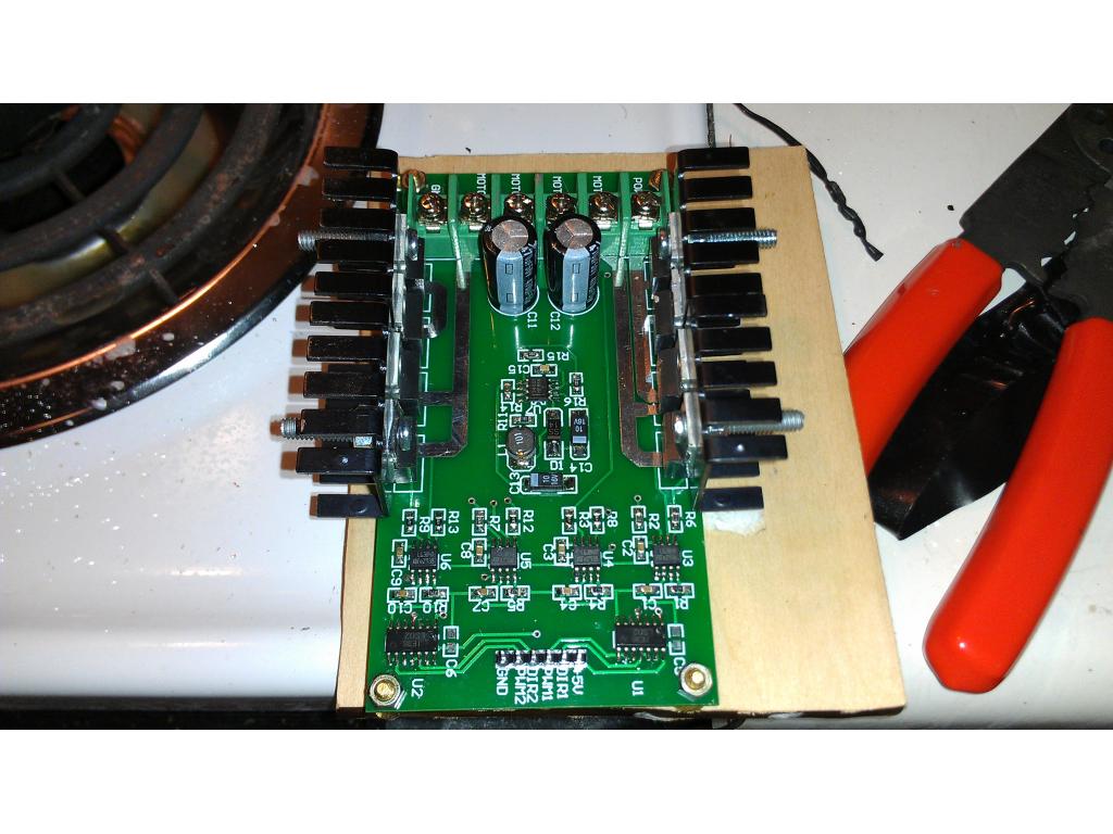
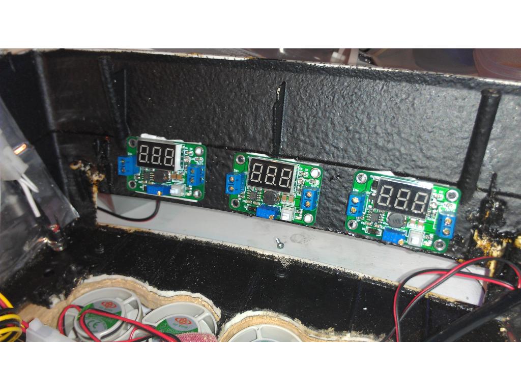
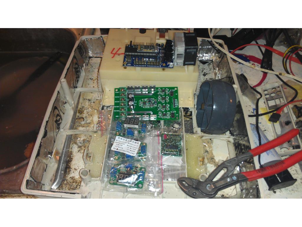
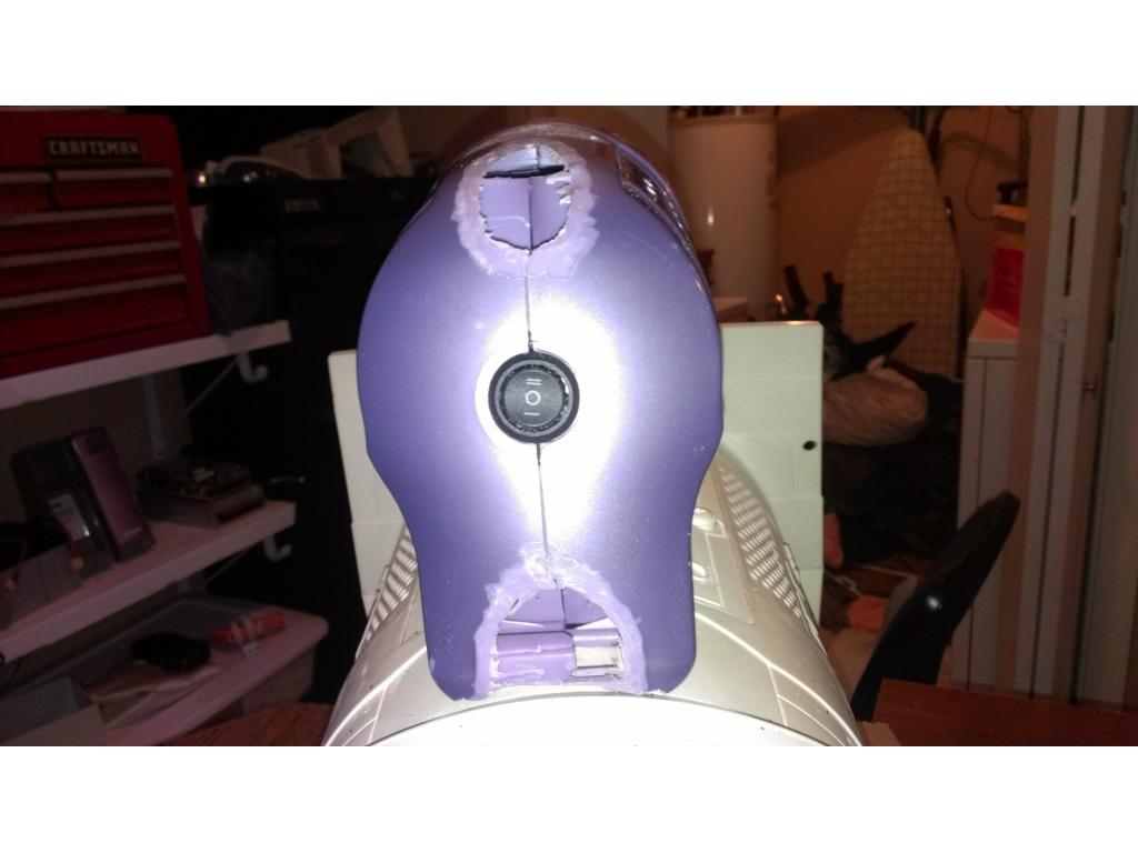
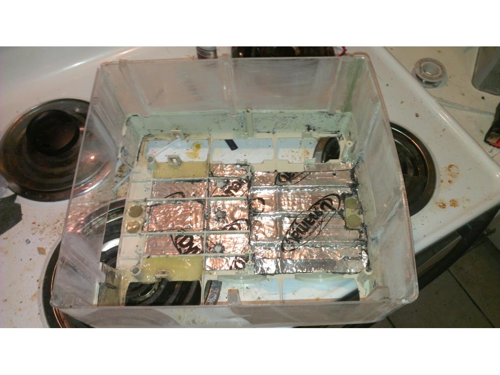
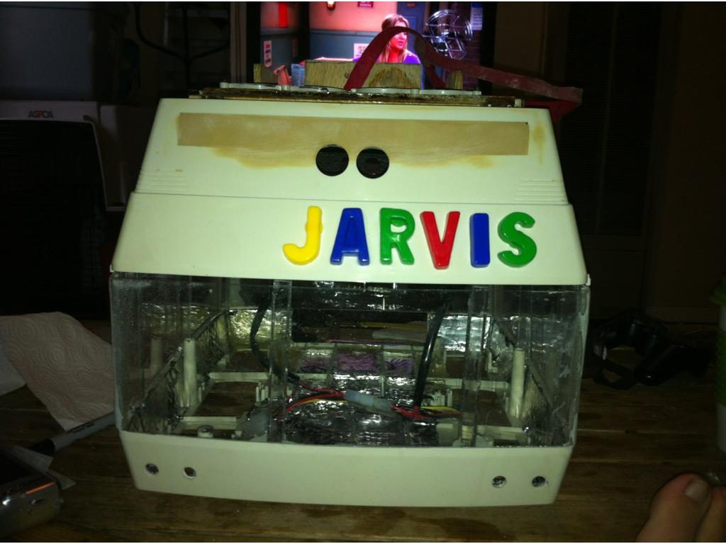
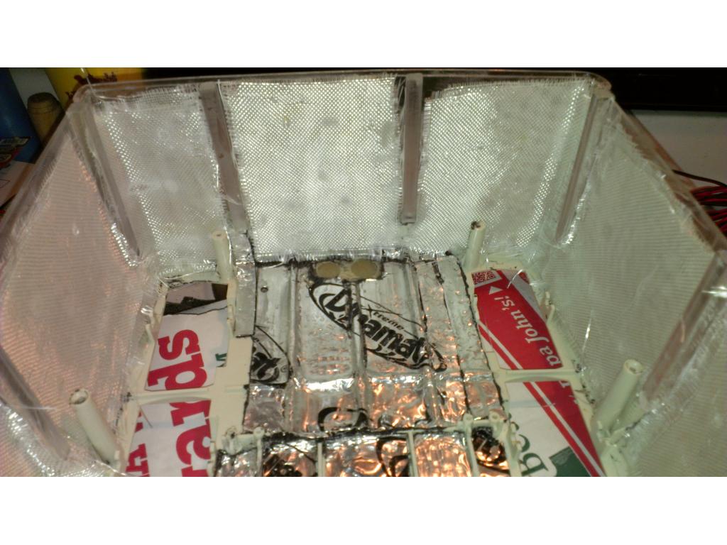
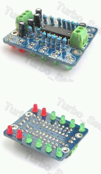
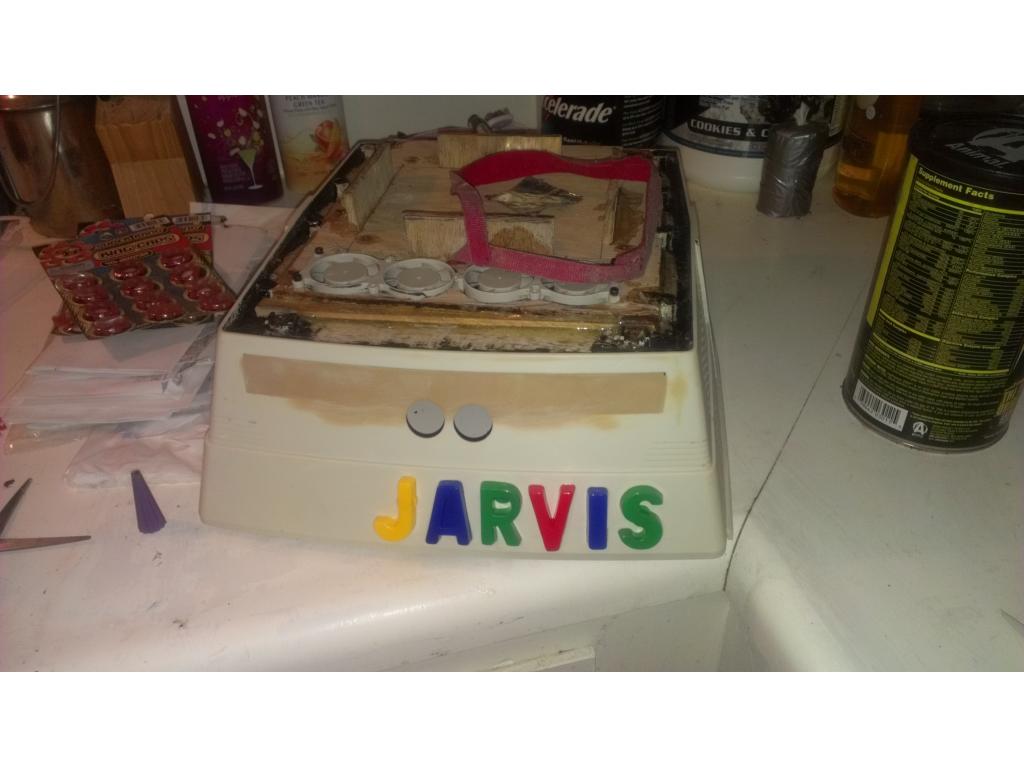
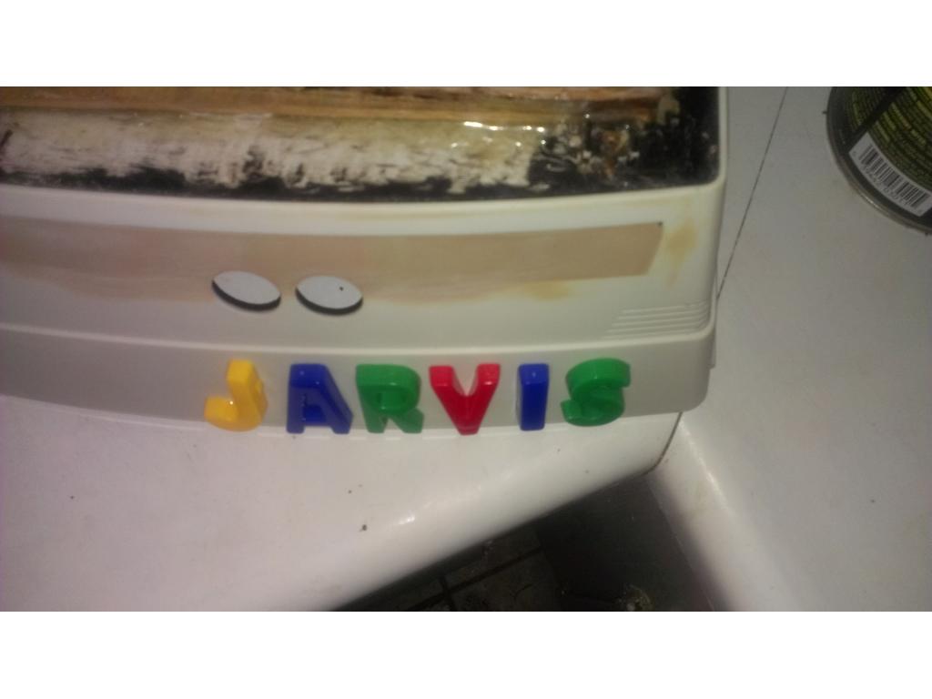
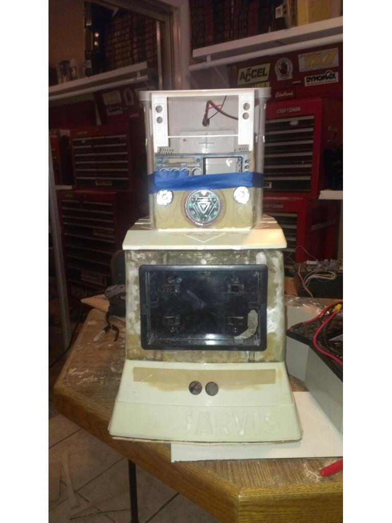
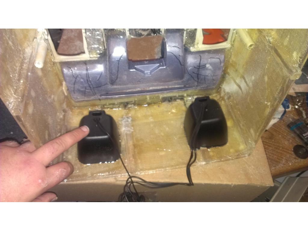
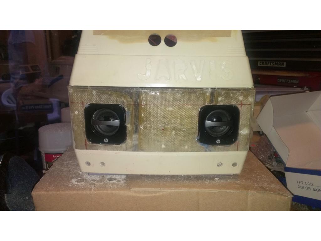
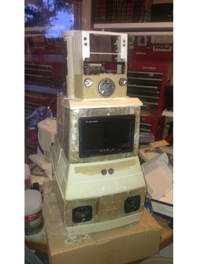
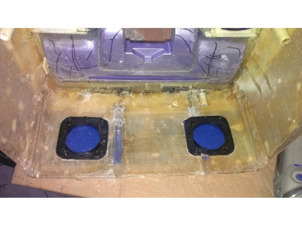
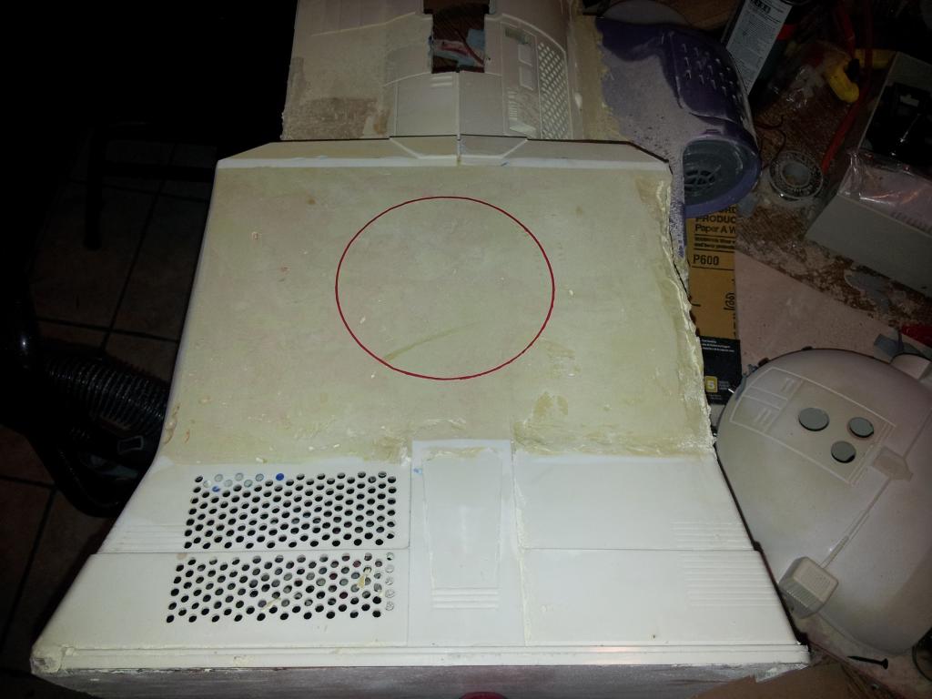
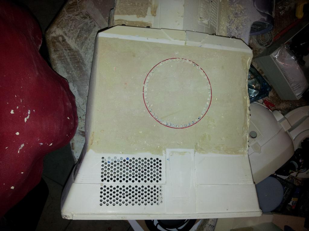
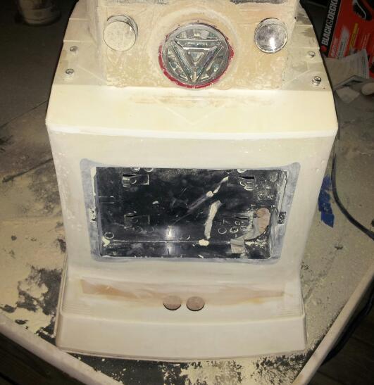
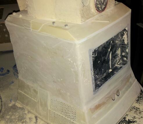
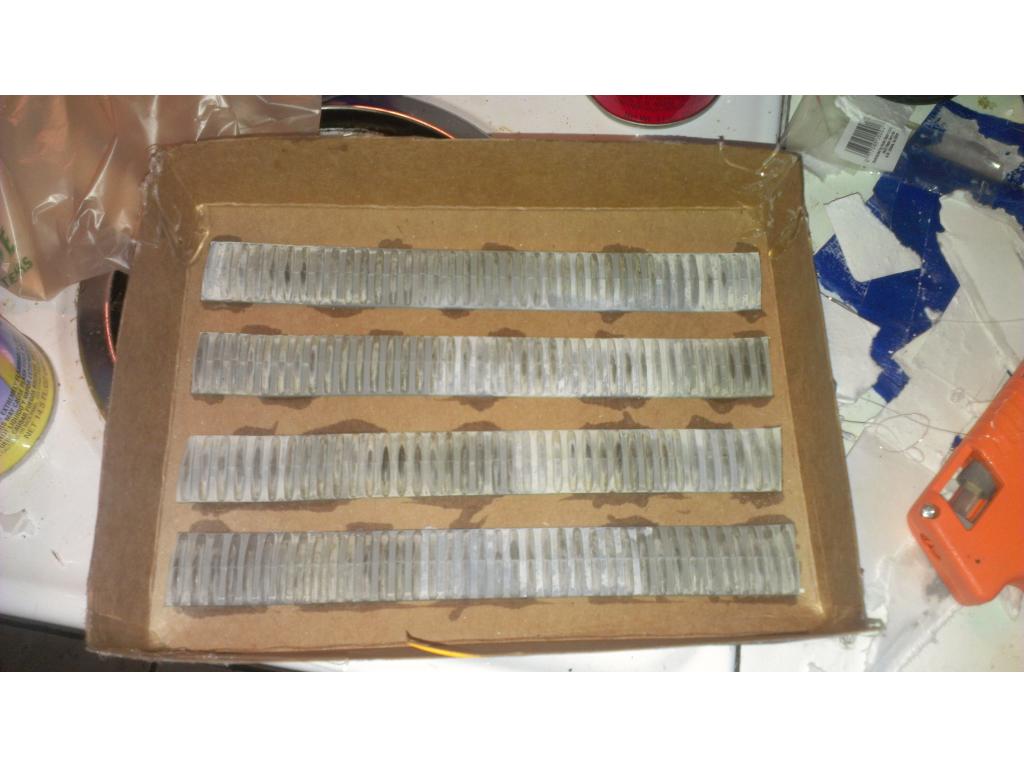
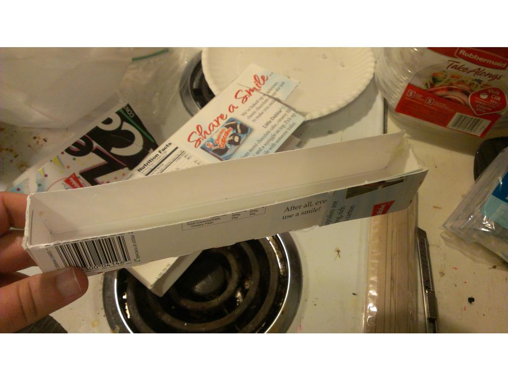
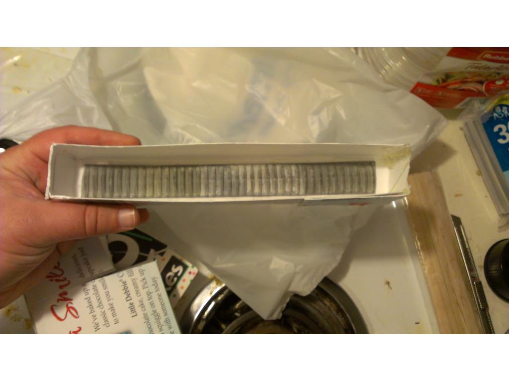
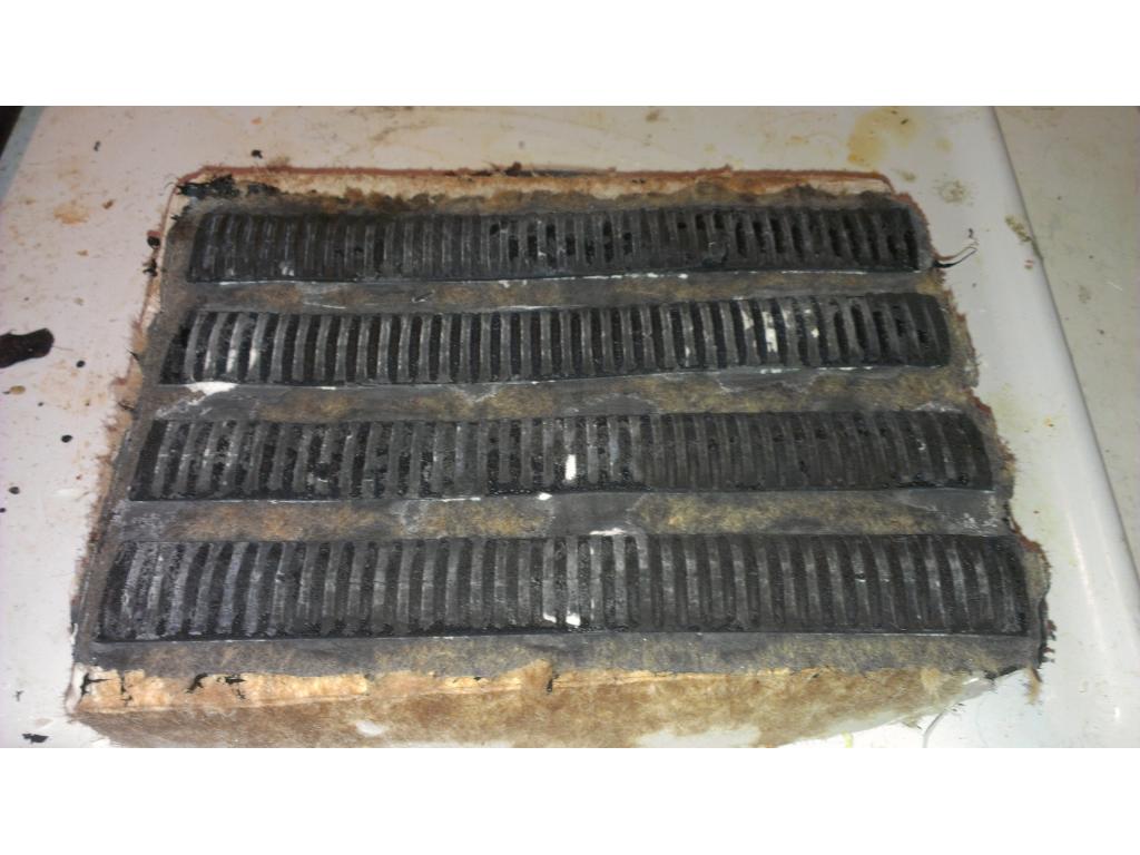
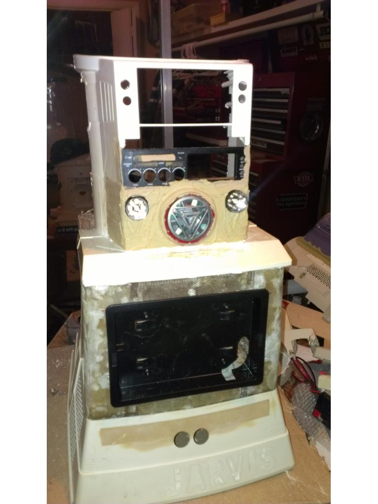
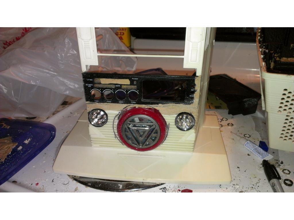
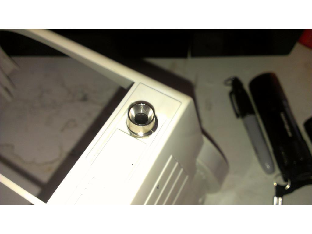
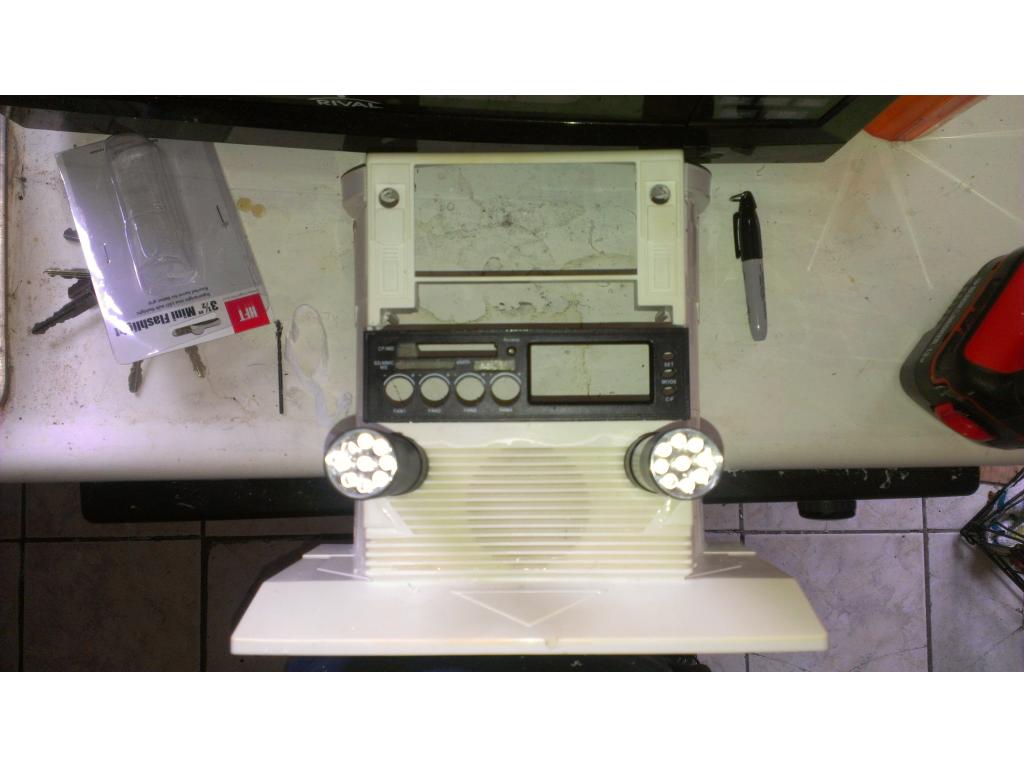
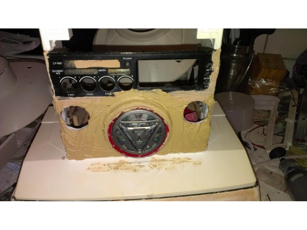
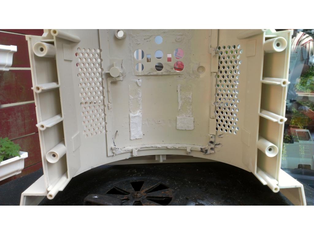
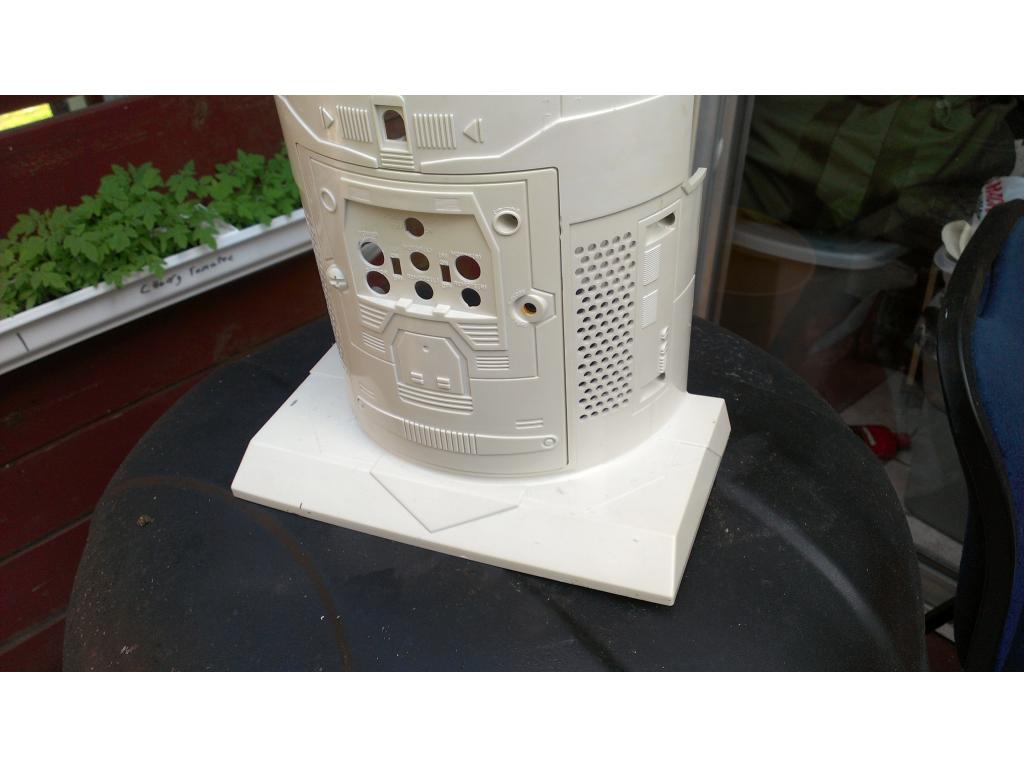
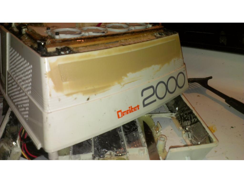
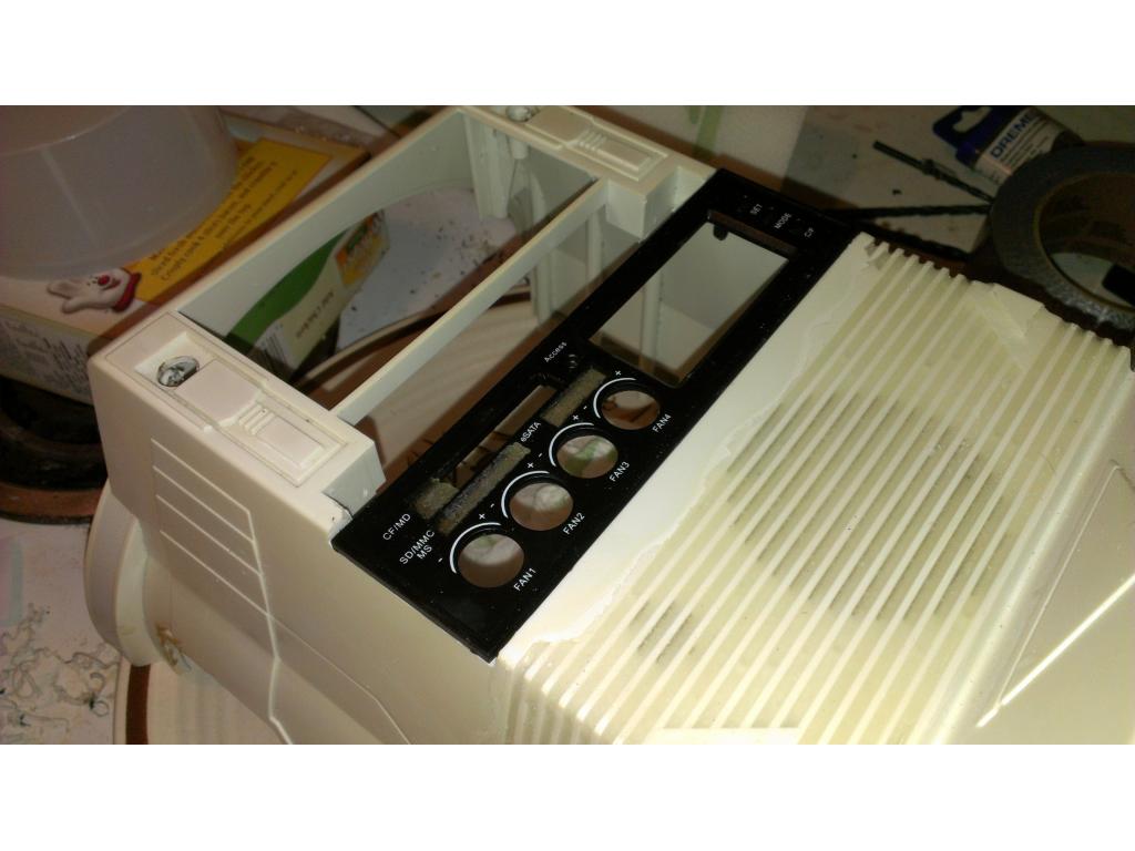
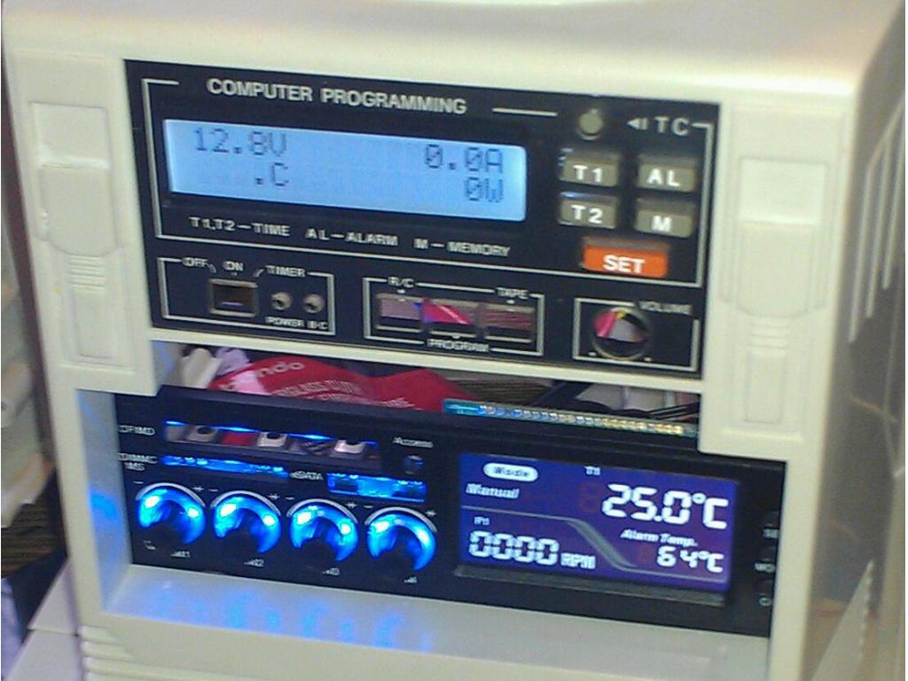
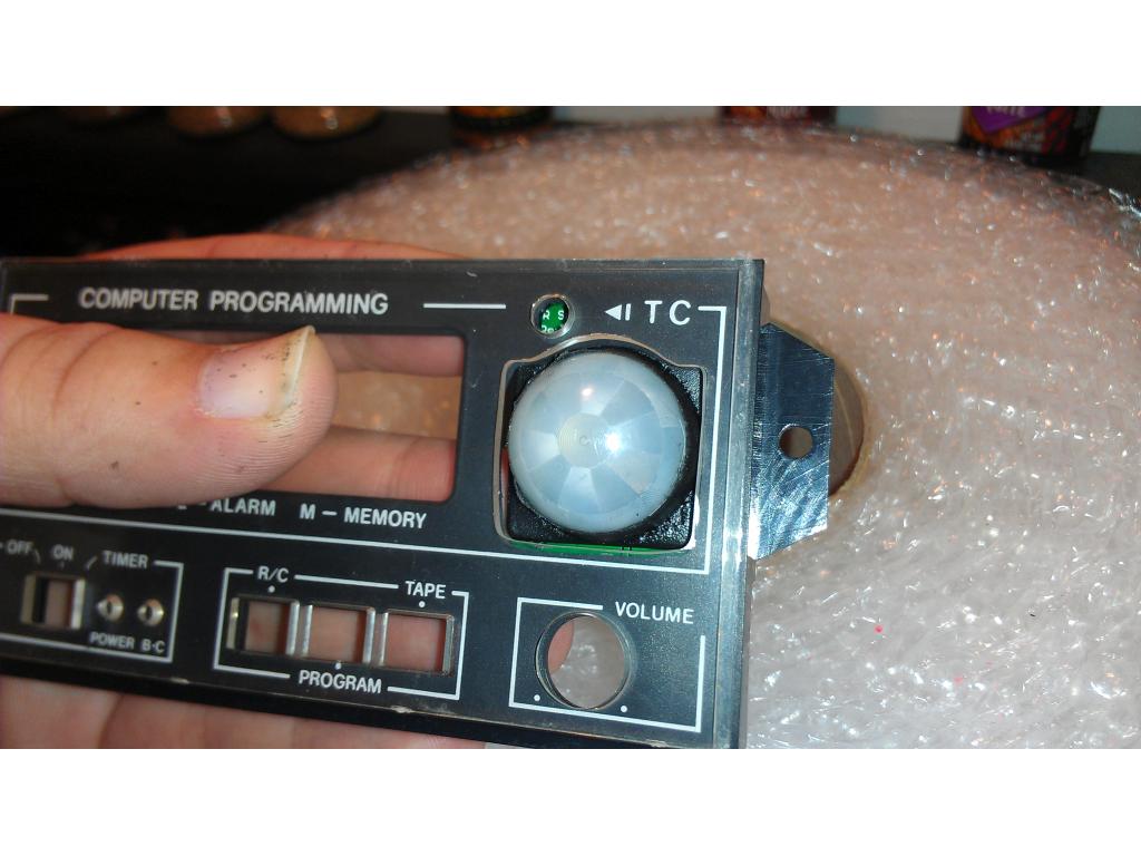
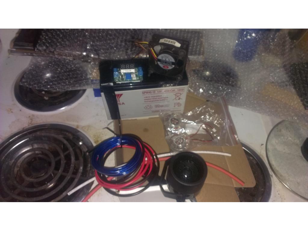
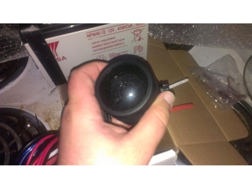
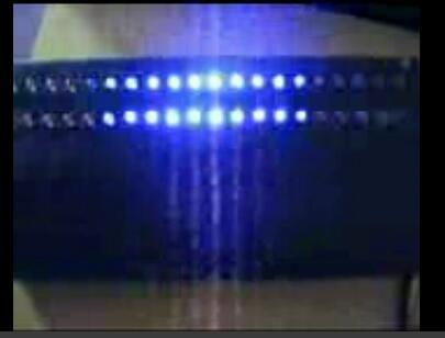
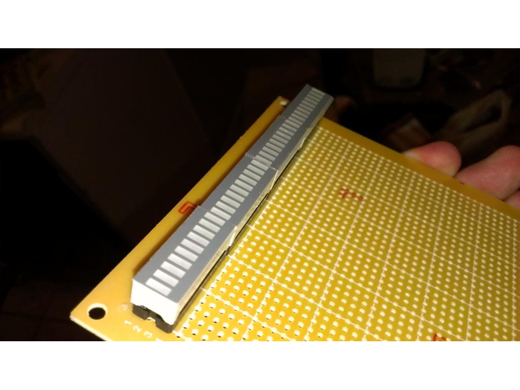
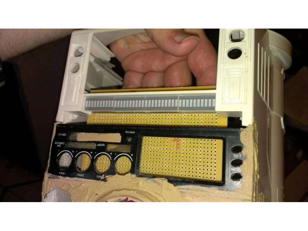
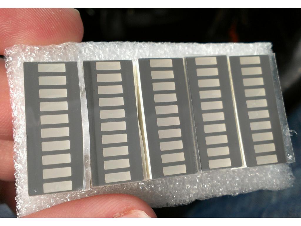
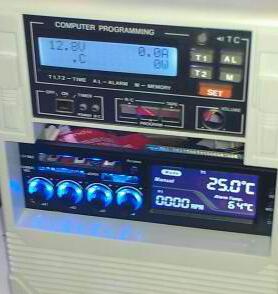
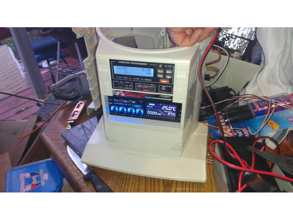
Ok after careful measurements I found 4 segment led bars fit perfectly right below the power management display.

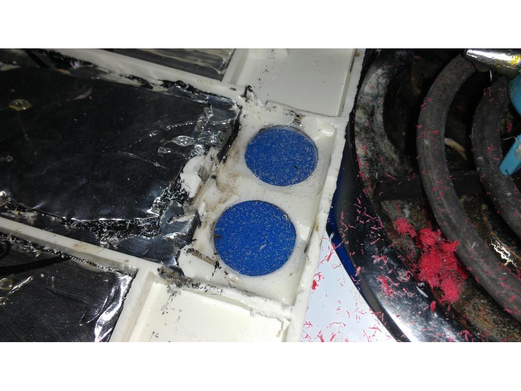
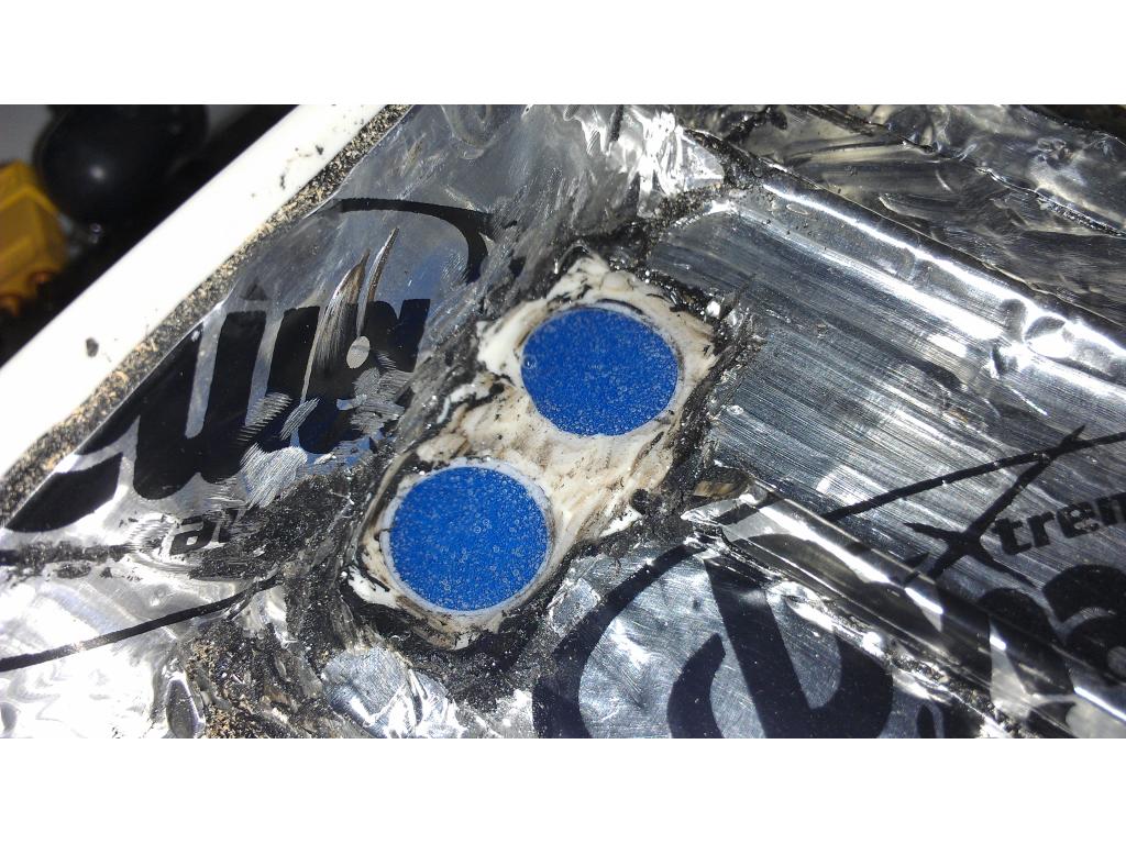
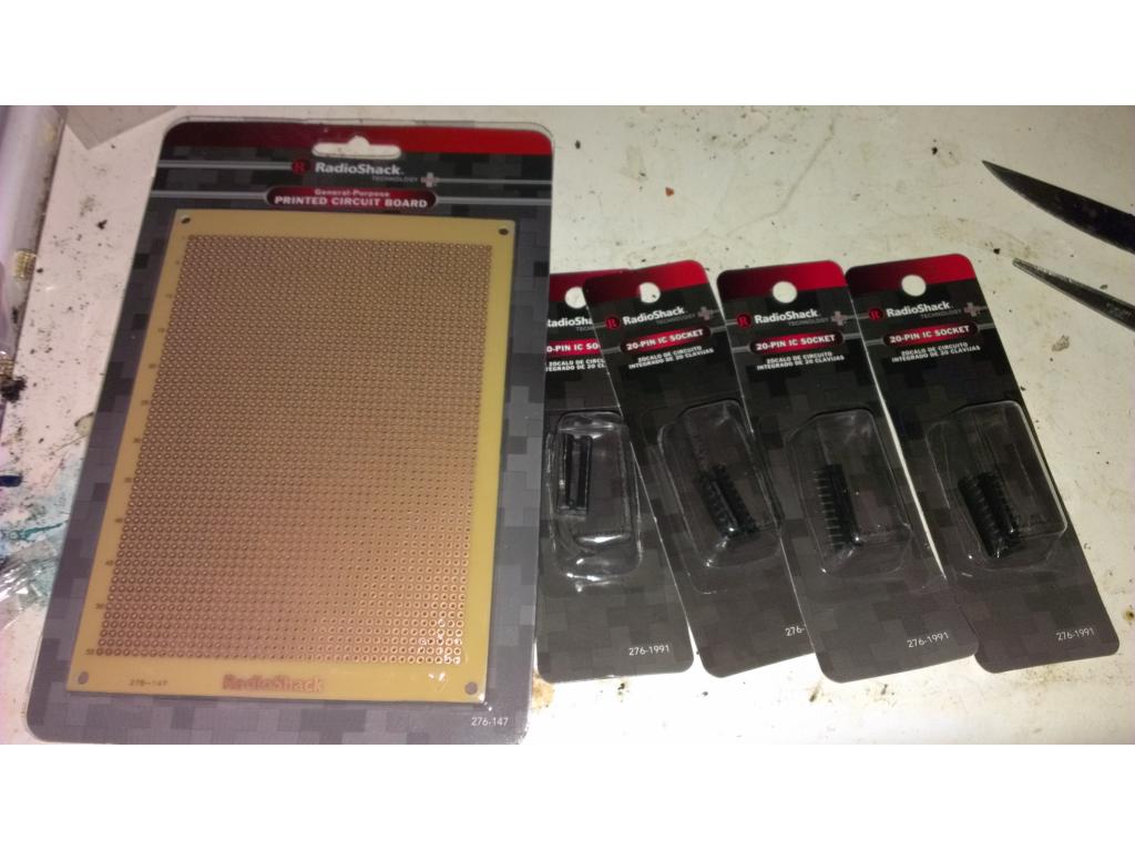
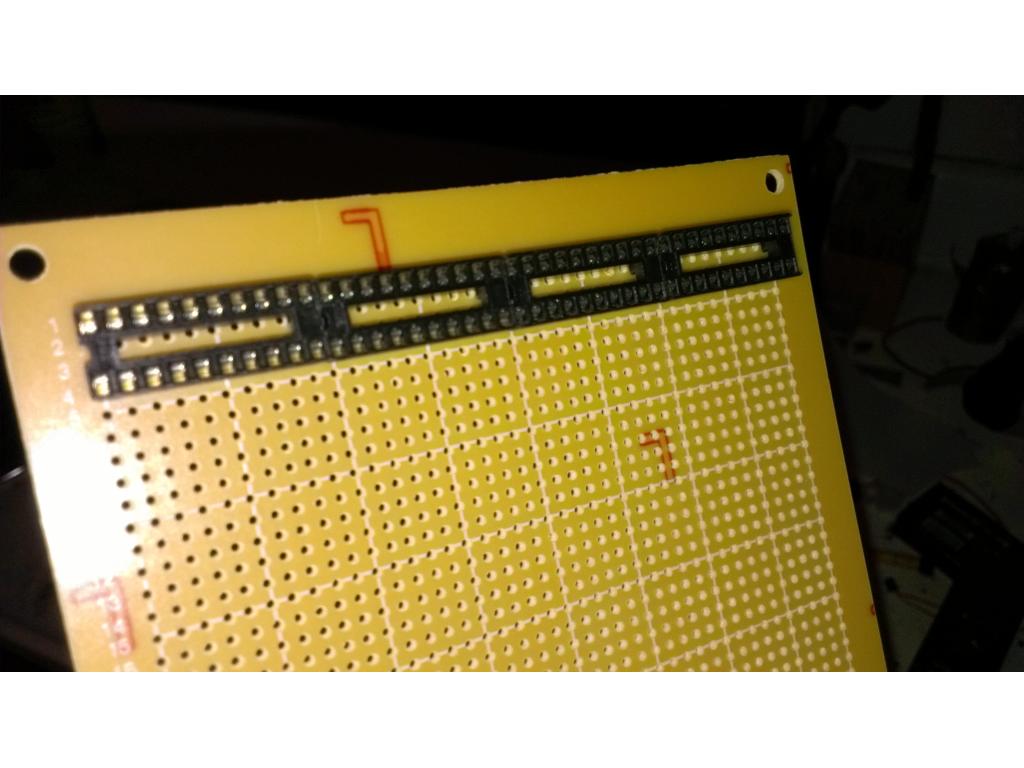
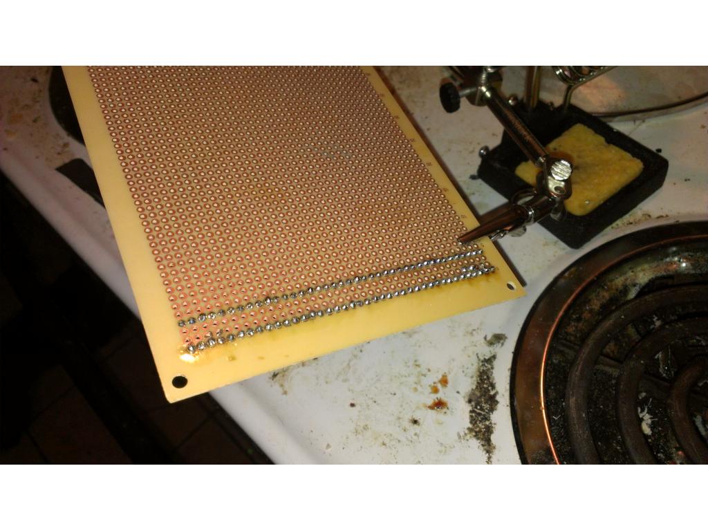
I bought 4 20 pin ic plugs and a copper tinned perfboard.
Using the solder I dotted each pin of the IC plugs. Using plugs give flexible.options for replacement or if the board.must be remade I didn't need to worry about the pricy led bars being.damaged during desoldering.
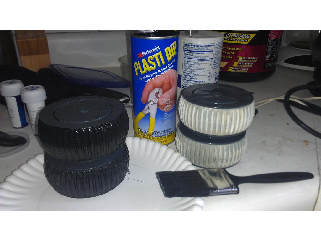
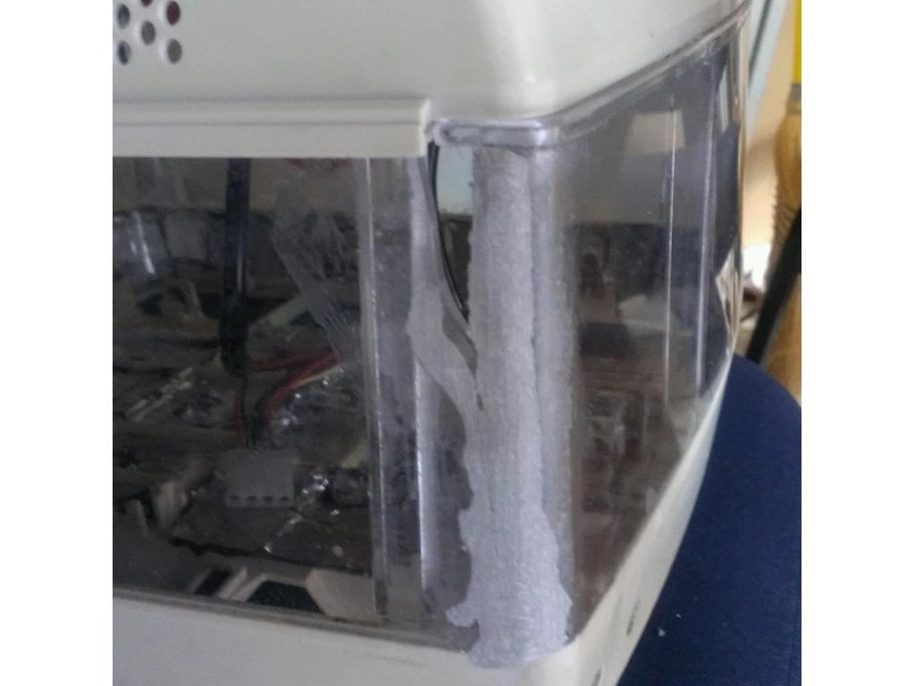
Here I can show you the bars by just holding them in their future mounting position. I will not cut the board till I get the controller chip ect for the LEDs.I either want to do a "kit" or Cylon blue dot scanning back and forth or preferably when the robot speaks the LEDs light starting at the center out to the edges. Any help with getting a chip or kit to do.this would be great. Please be specific , provide links and prices ect so that suggestions are productive.
Could any of these work for your scanning part?
Bowdens hobby circuits
Ok found it! It's a Led vu meter , https://www.youtube.com/watch?v=t05lLKZYxU8&feature=youtube_gdata_player
Lm3915 vu led driver
I found the chip itself but now I gotta figure out how to utilize it to make it work just like the video but with 40 bar LEDs. Somone know where to find a schematic to accommodate 40 LEDs? The ones I have been seeing are 10 or 20 LEDs.
If you cant find one for 40, can you expand it by wiring 2 leds to one?
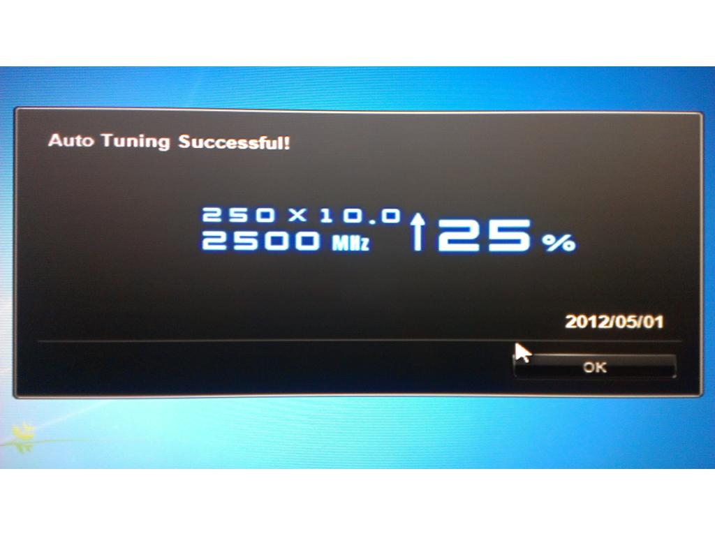
---almost to 100 pages Josh!---
Technically every 2 LEDs could be paralleled but that doubles current draw on that output and I believe all the resistors must be different to accommodate double the current. My basic advanced electronics class for IC , and stuff like that was 12 yrs ago lol. Thanks on being close to 100 , soon as this guy gets to paint I'm opening a new thread.
Right, thats true you will have to modify it a bit but will that type of display be ok with you?
Well the display would look.the same either way , I mean it would be blue led bar. Obviously the only other thing I would consider is the kit knightrider scanning lights , but being a vu meter when sound comes from my bot there's also the visual indicator looking at the video I think. It looks cool.
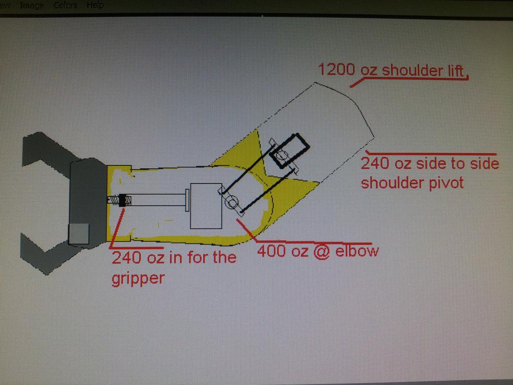
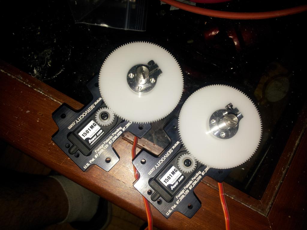
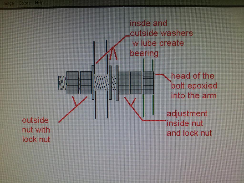
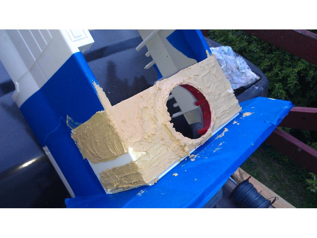
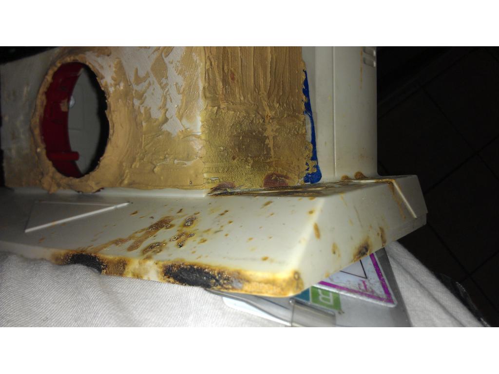
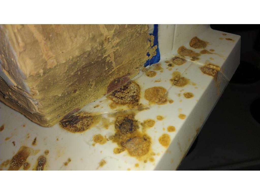
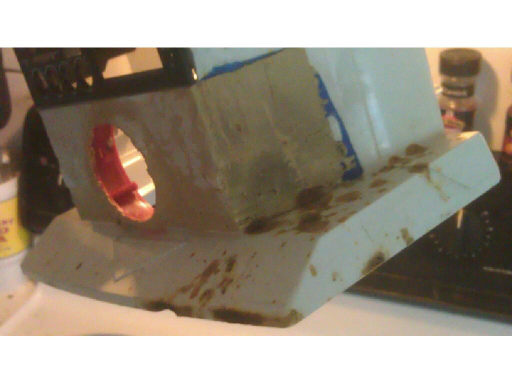
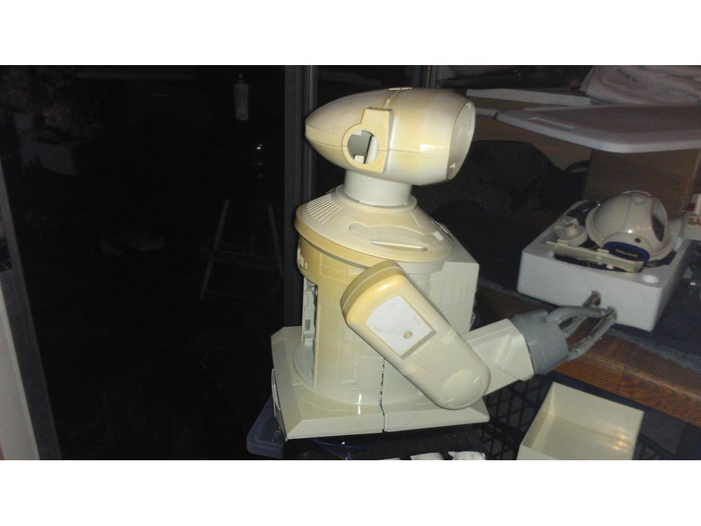
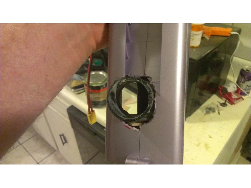
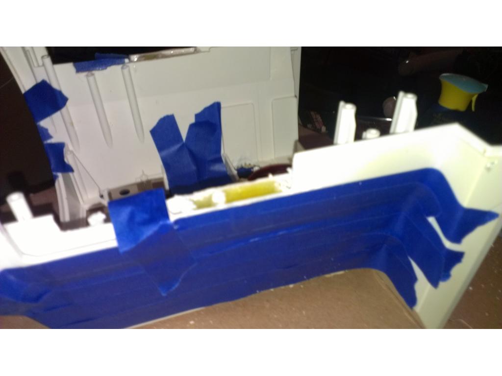
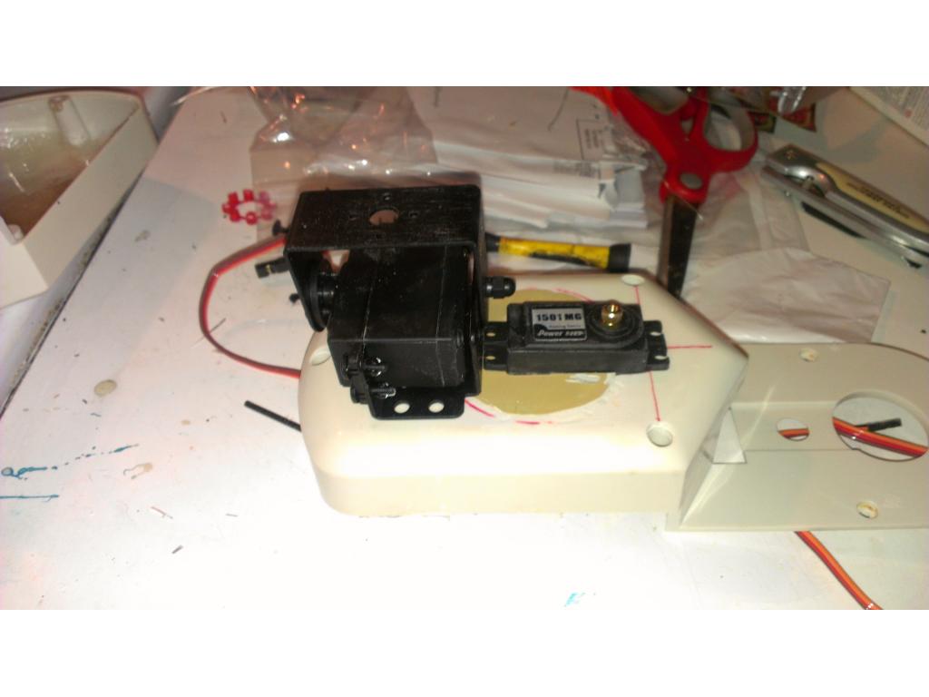
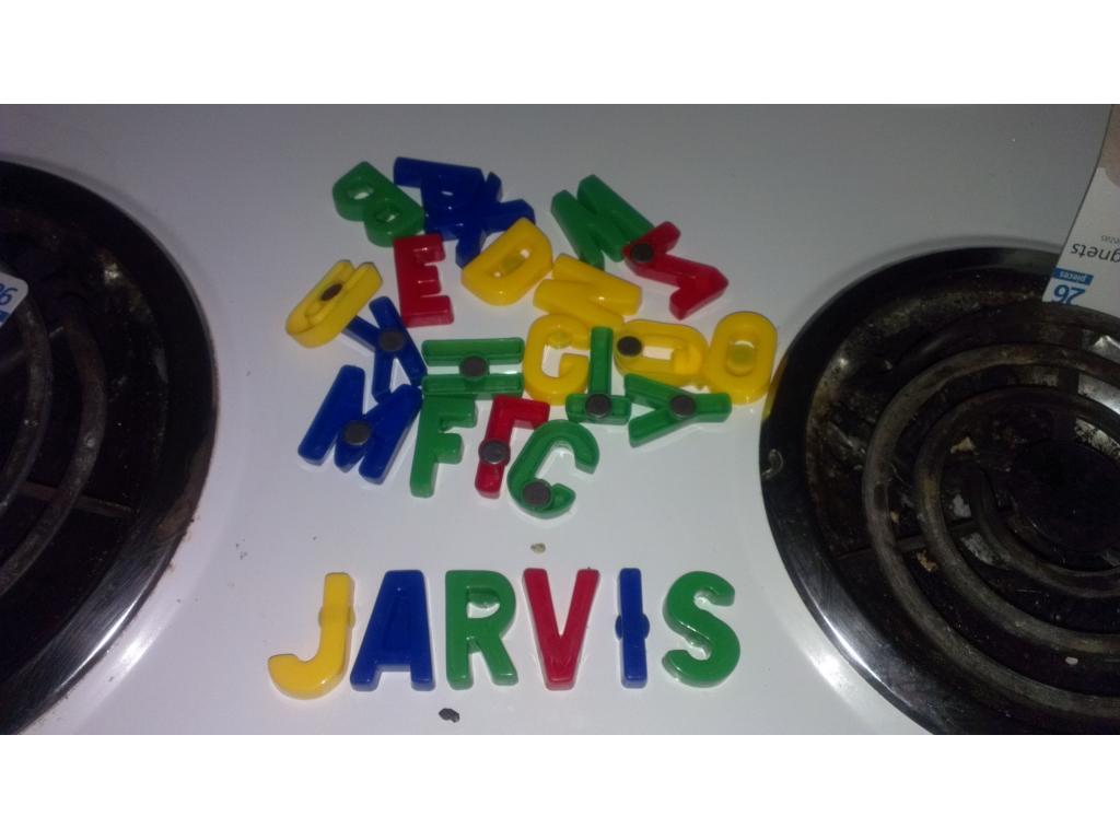
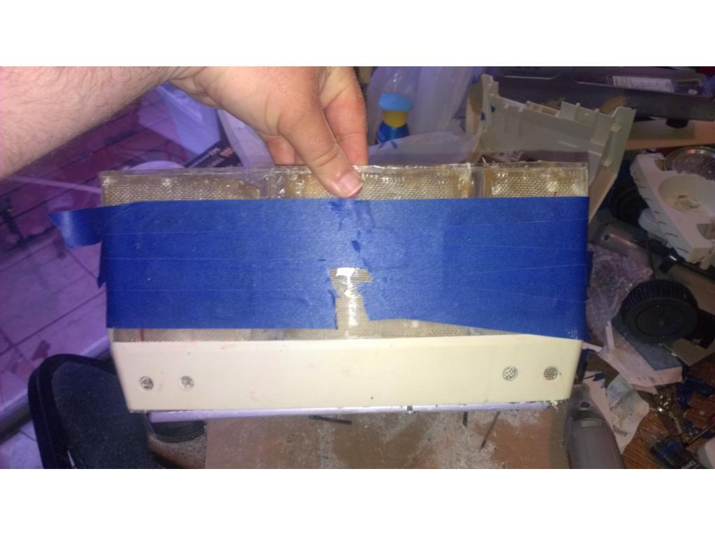
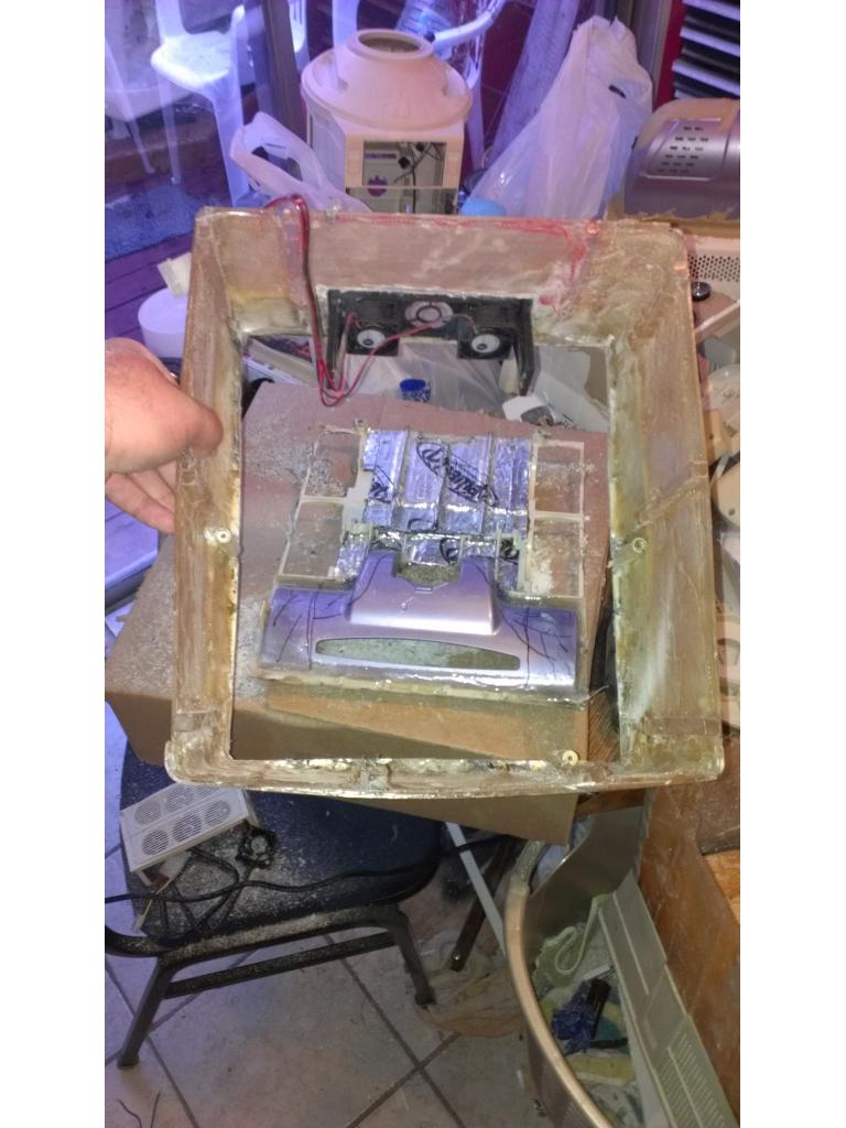
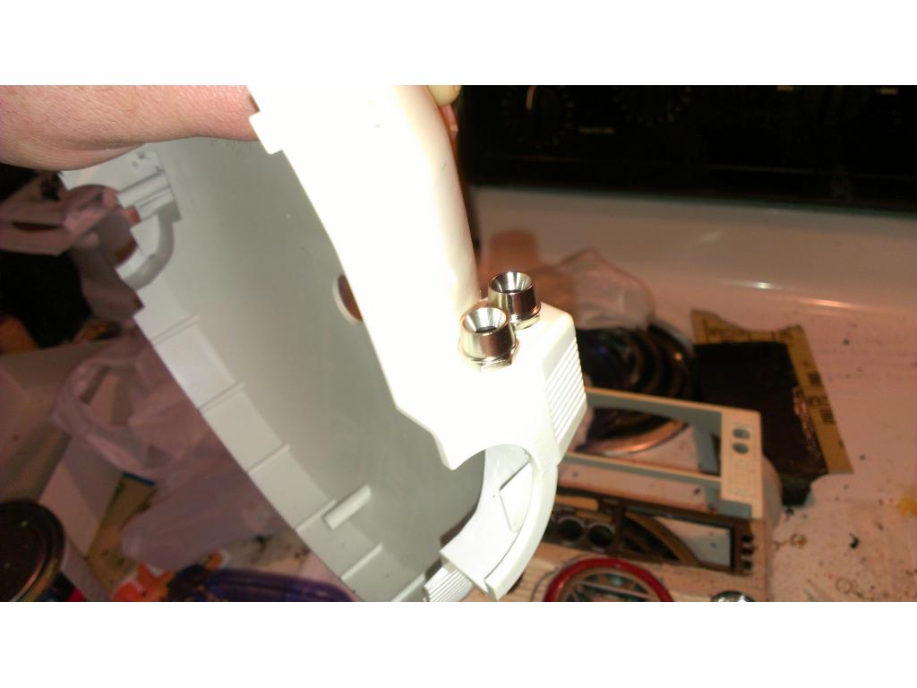
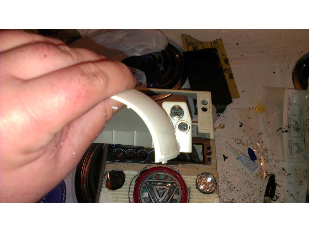
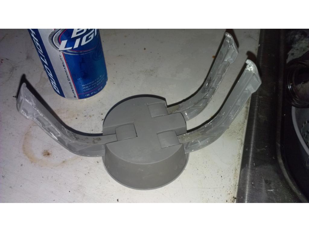
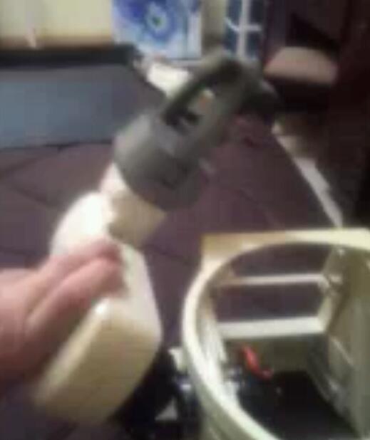
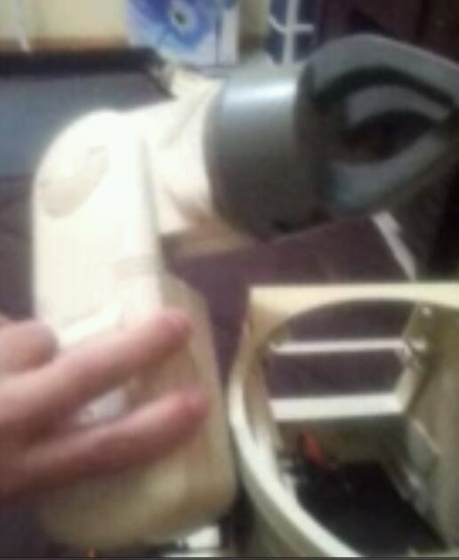
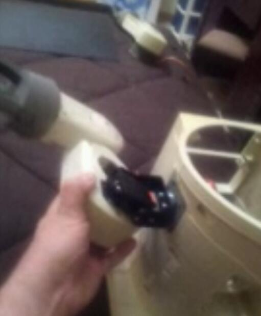
Oh! Off subject a little- looking at the tight area of the upper arm when I saw you taped the bracket farther back I saw that would do two.things , give me room for the elbow servo and gives Jarvis 2 to 3 inches longer reach so he has arms long enough to grab something off the table without hitting it. Pictures will follow tommorow.
It definately does give you more reach. If it turns out to tax your servo too much you could always put it back near original point. Will you be reinforcing the plastic at the shoulder?