


-634700966886250000.jpg)
-634700967015000000.jpg)
-634700967157968750.jpg)
-634702814800312500.jpg)
-634702600865468750.jpg)
-634702601116718750.jpg)
-634702602252031250.jpg)
-634702602665625000.jpg)
-634702602851875000.jpg)
-634694134410000000.jpg)
-634693960892812500.jpg)
-634693961752343750.jpg)
-634693953179375000.jpg)
-634693953336093750.jpg)
-634693164809062500.jpg)
-634693165327500000.jpg)
-634693165925625000.jpg)
-634693166147343750.jpg)
-634786542943876953.jpg)
-634796120303593750.jpg)
-634796120470312500.jpg)
-634812479455986328.jpg)
-634812479726035156.jpg)
-634812480620283203.jpg)
-634812481334052734.jpg)
-634812482341699218.jpg)
-634822681001005859.jpg)
-634822681580644531.jpg)
-634822681777470703.jpg)
-634821106166250000.jpg)
-634821106572812500.jpg)
-634821106815625000.jpg)

-634814909605058593.jpg)
-634814909850224609.jpg)
-634814910193212890.jpg)
-634814910596445312.jpg)
-634820188048437500.jpg)
-634820188647187500.jpg)
-634820189032656250.jpg)
-634718079154687500.jpg)
-634718080622031250.jpg)
-634714909191250000.jpg)
-634714909644843750.jpg)
-634713078392031250.jpg)
-634713078781250000.jpg)
-634720009877968750.jpg)
-634749341545937500.jpg)
-634749341951406250.jpg)
-634732946203437500.jpg)
-634708797562402343.jpg)
-634706000248750000.jpg)
-634705927185312500.jpg)
-634705927626406250.jpg)
-634705928146250000.jpg)
-634705929045781250.jpg)
-634705929717812500.jpg)
-634705930336093750.jpg)
-634705930540468750.jpg)
-634705931037812500.jpg)
-634709695807265625.jpg)
-634709696076181640.jpg)
-634711364771718750.jpg)
-634711364485781250.jpg)
-634712172318906250.jpg)
-634771897291406250.jpg)
-634771897466093750.jpg)
-634771897849687500.jpg)
-634771898236093750.jpg)
-634771898712187500.jpg)
-634771899102656250.jpg)
-634771899822656250.jpg)
-634771900771562500.jpg)
-634771901301875000.jpg)
-634768466924746093.jpg)
-634768467383681640.jpg)
-634772580489218750.jpg)
-634772581075781250.jpg)
-634772581532343750.jpg)
-634772581721718750.jpg)
-634773400815625000.jpg)
-634773401032187500.jpg)
-634781365777988281.jpg)
-634781366040302734.jpg)
-634781366299042968.jpg)
-634766553798554687.jpg)
-634766556025839843.jpg)
-634759732245312500.jpg)
-634765021896093750.jpg)
-634765022115000000.jpg)
-634765022326562500.jpg)
-634765023386093750.jpg)
-634765855550937500.jpg)
-634765856533437500.jpg)
-634765856756250000.jpg)
-634845177217089843.jpg)
-634845177425585937.jpg)
-634857207521406250.jpg)
-634857208212500000.jpg)
-634857208786718750.jpg)
-634826982093593750.jpg)
-634838602835000000.jpg)
-634838603089687500.jpg)
-634838603585312500.jpg)
-634871181815468750.jpg)
-634871183099531250.jpg)
-634871128238750000.jpg)
-634870976497031250.jpg)
-634870976894687500.jpg)
-634880528374375000.jpg)
-634880528707656250.jpg)
-634880529073593750.jpg)
-634892824736386719.jpg)
-634892824903066406.jpg)
-634892825090117187.jpg)
-634892825255283203.jpg)
-634880812756406250.jpg)
-634870194470625000.jpg)
-634870194829687500.jpg)
-634865232676250000.jpg)
-634863402043750000.jpg)
-634863402351562500.jpg)
-634863402584218750.jpg)
-634863404238125000.jpg)
-634869405242656250.jpg)
-634869405424687500.jpg)
-634869405586562500.jpg)
-634869405943906250.jpg)
-634869406072656250.jpg)
-634869404353281250.jpg)
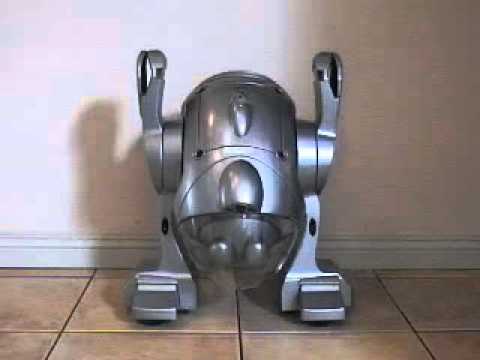
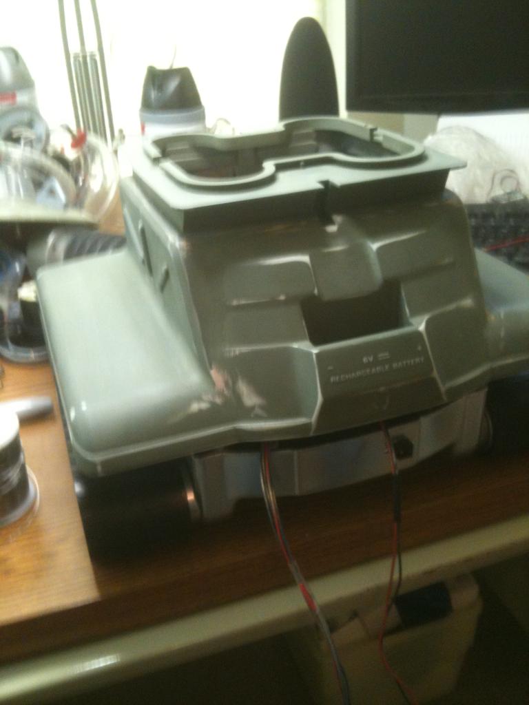
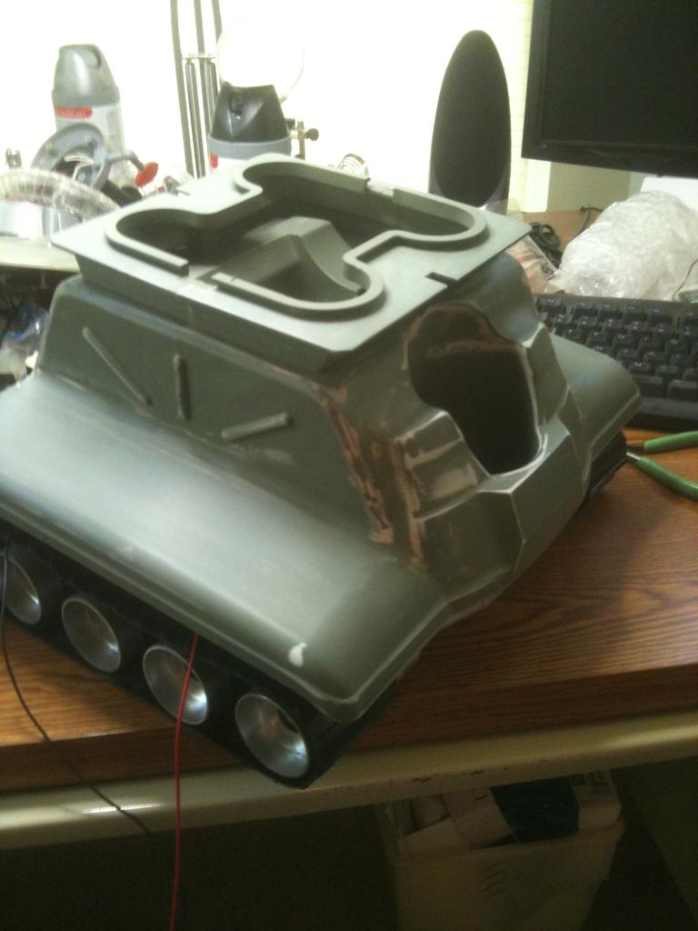
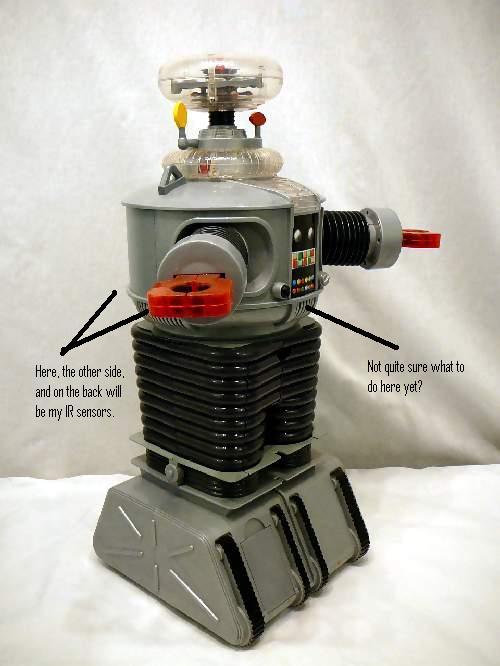
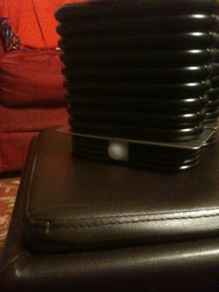
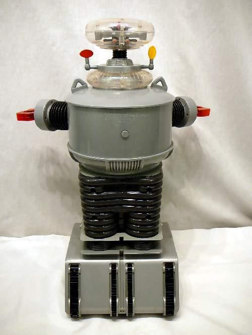
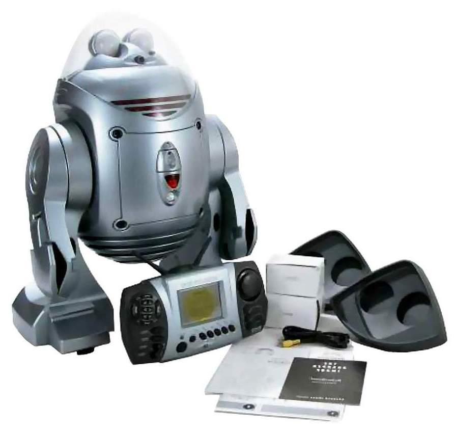
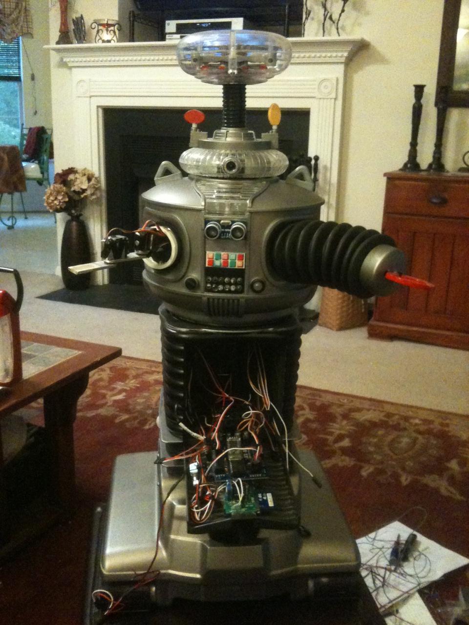
Now that I have finished B.O.B., my get your feet wet bot, I have begun my next hack. This next robot will bridge the gap between Bob and my ultimate big robot. I am starting with a remote controlled B9 toy from Trendmasters. It was very limited in what it did, and the drive section was pathetic, but it was B9!
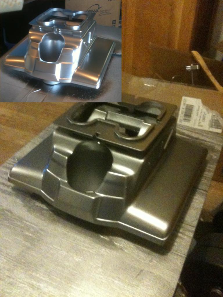
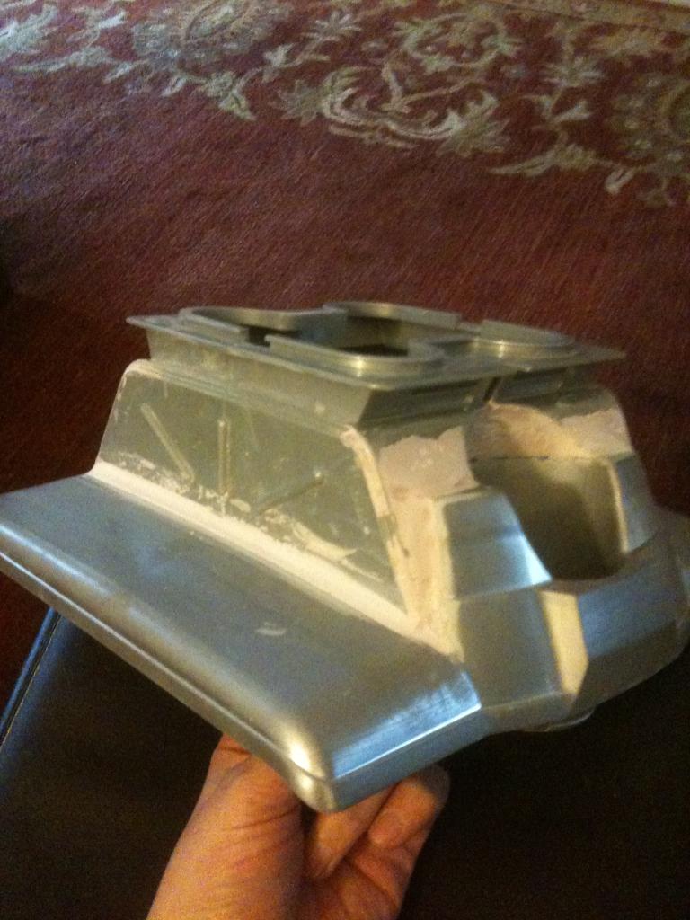
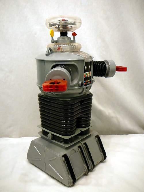
Before Pics:
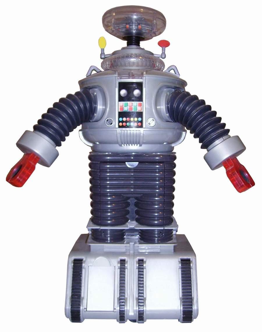

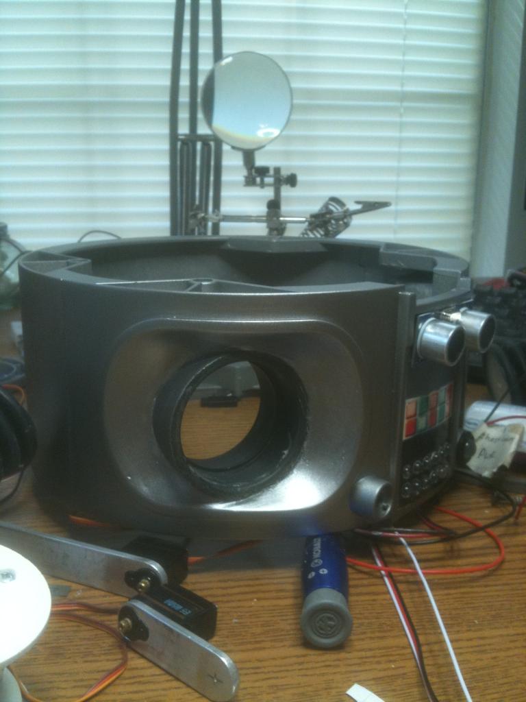
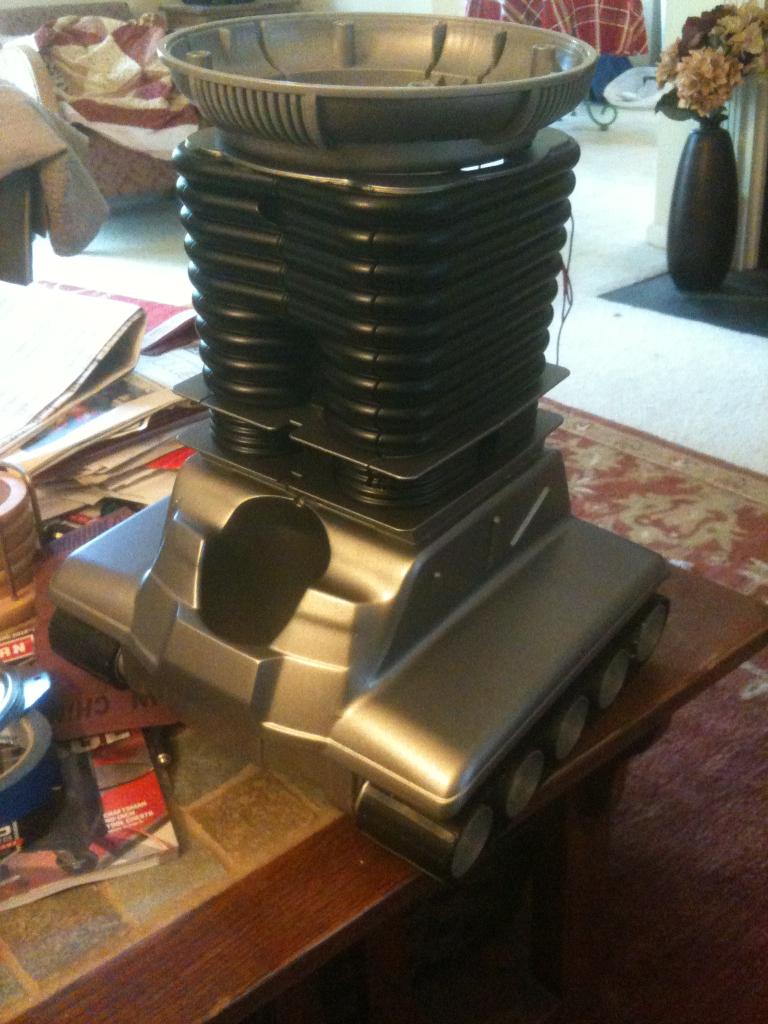
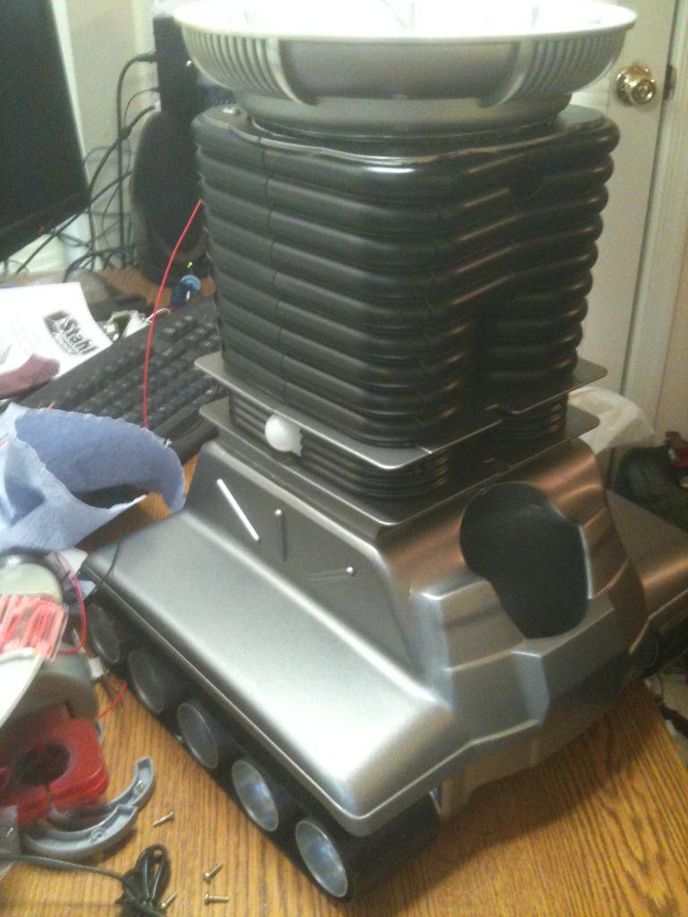
Here is what B9 looks like now:
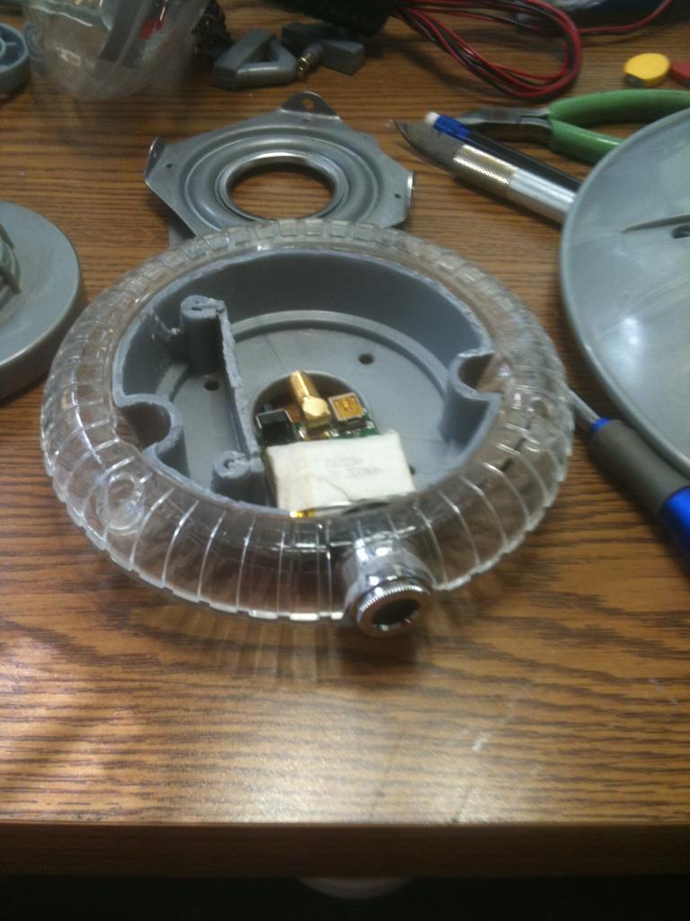
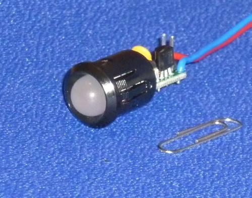
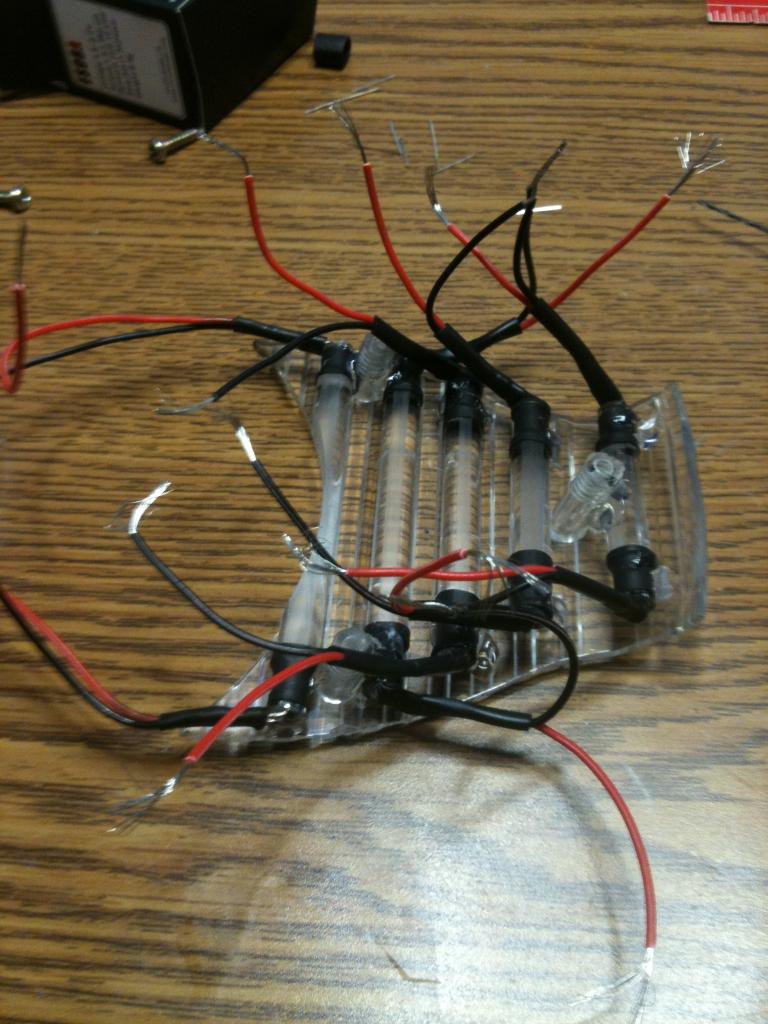
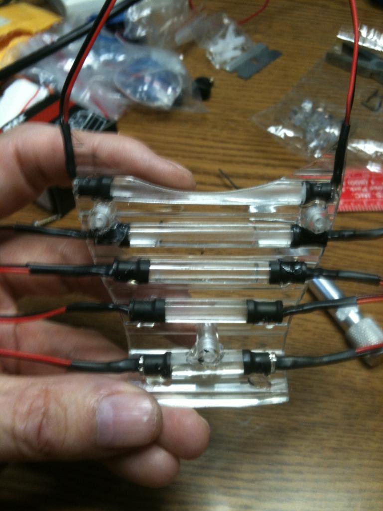
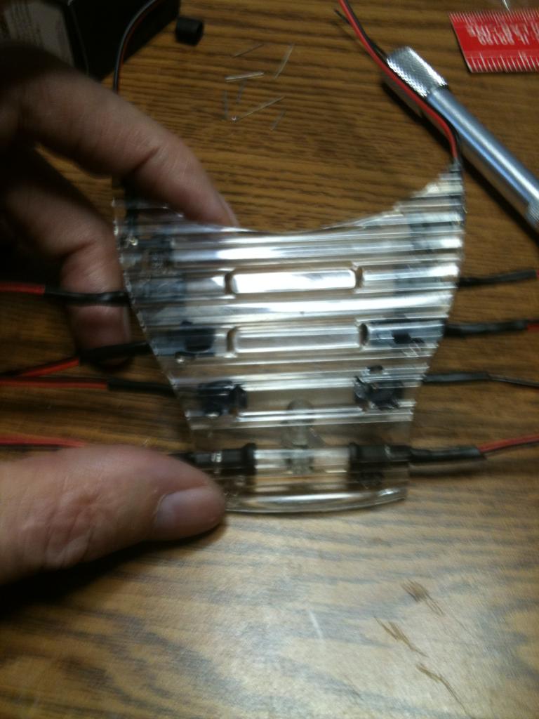
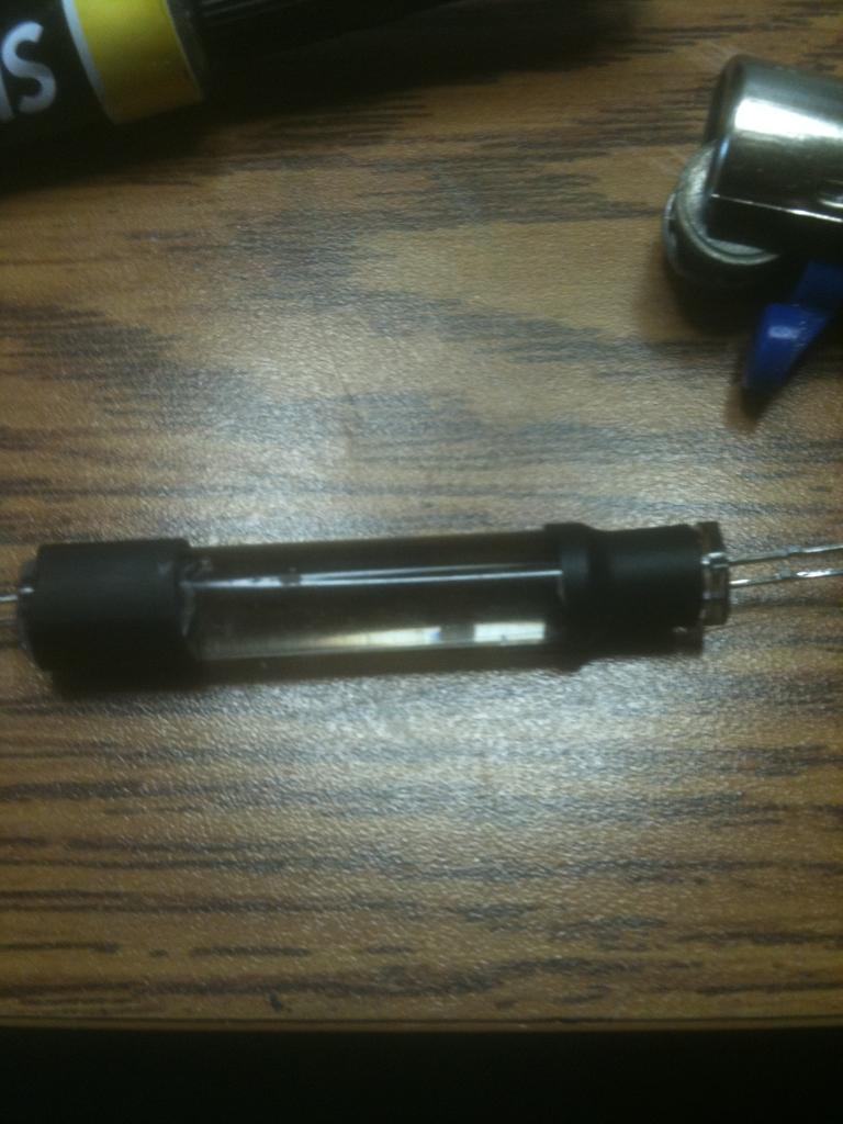
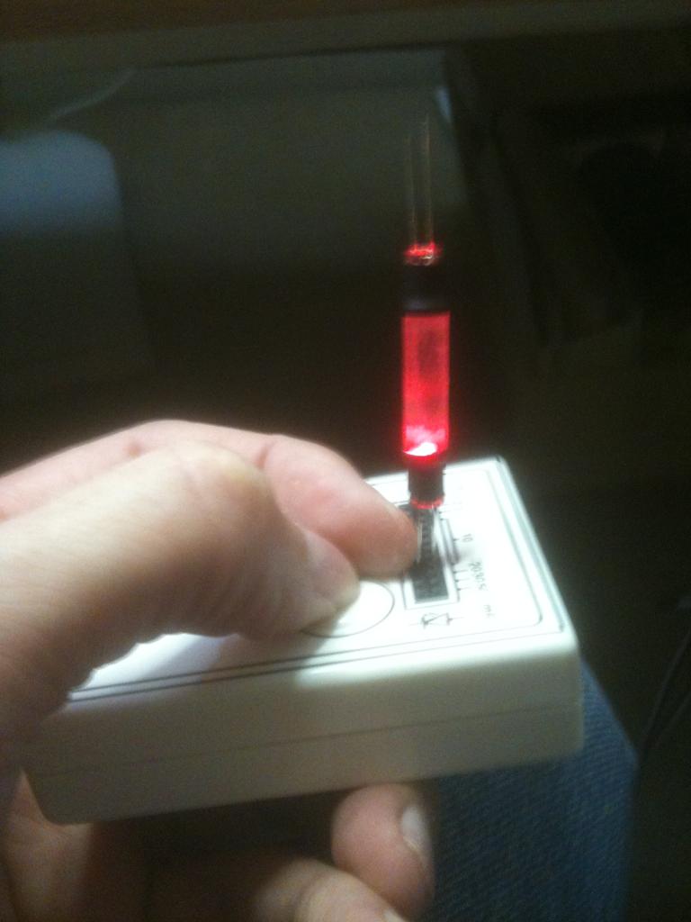
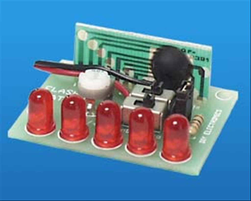
I have mounted clear LEDs in the appropriate colors in the chest at the bottom of the decal and have a flashing circuit that will blink them in the combination as seen on the series. Where the two large round circles are (white domes on the big guy) I will have my ping sensor. I have mounted pager motors in the antenna housings to turn the "sensors" as seen in the TV version. I have mounted red El Wire to his voice plate to emulate the original as well. I have also mounted a series of blinking LEDs to the "brain" section in the bubble.
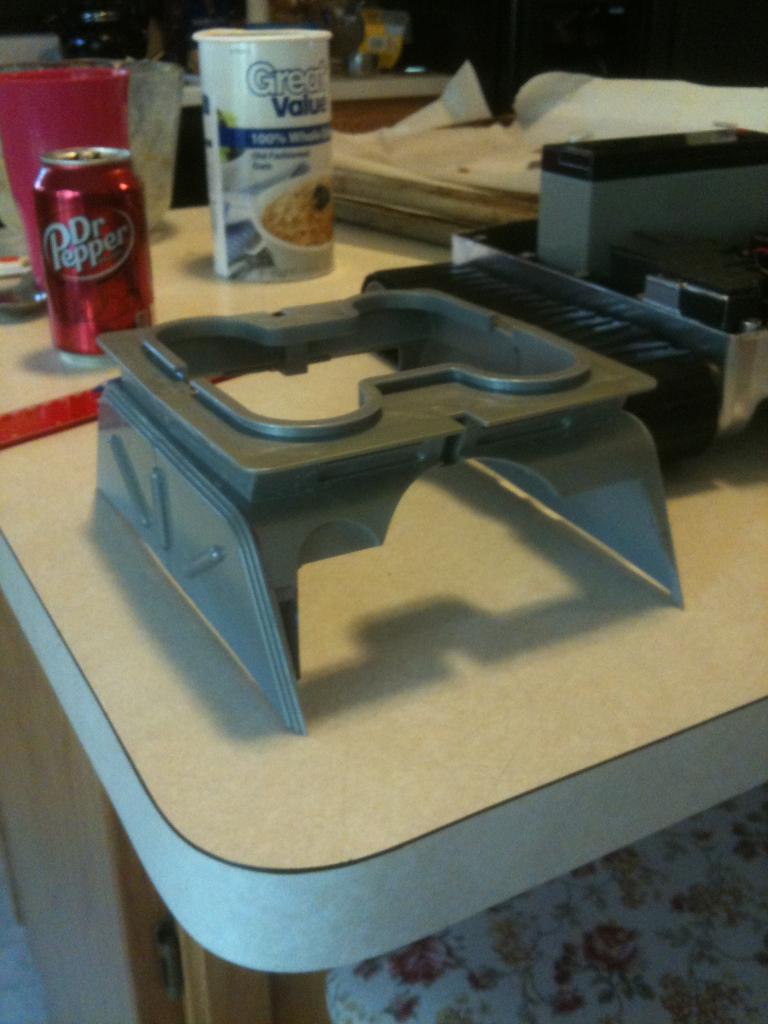
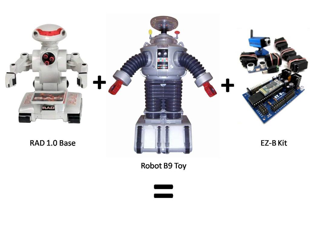
Next is to work on the rotation of the bubble and torso, articulate the arms and claws, and make a real functioning tread section. For the tread section I am adapting the base from my RAD robot. I will keep you posted with pics as I proceed.
Thanks,
Bret
Discover more robots
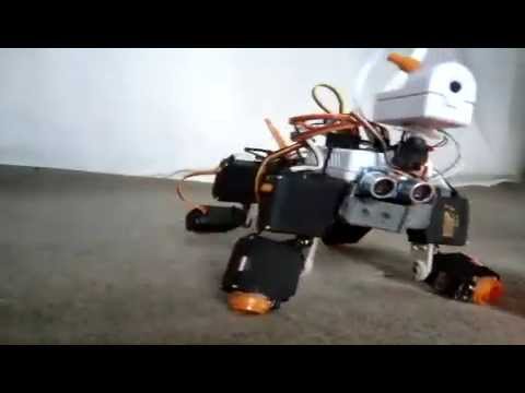
Ericez's Dog The Little Robodog Ez-B V.4
Jeffmorris's Homemade Biped Robot

Hey.Brett , I understand your concern , but we gotta take in mind some.things. his tank is a large 1:27 scale with real all metal gearbox and tracks which weight over 20 pounds. Also the Times he saw a spike was on carpet using a skid steering. Skid steering is one track on full and the other is being dragged which was stalling his motors Plus he undervolted them with is a reduce in torque and increase in current draw. On your bot I'm sure your savy enough NOT to use skid steering. Instead you reverse the opposite track and that elliminates the drag. Also your bot weights 1/2 and your base is plastic rubber with several inches wider from side to side which reduces turning drag. Best way to find out is to try. But if the amps were high like that other guys tank you could grab a 10a controller like me for about 25 shipped.
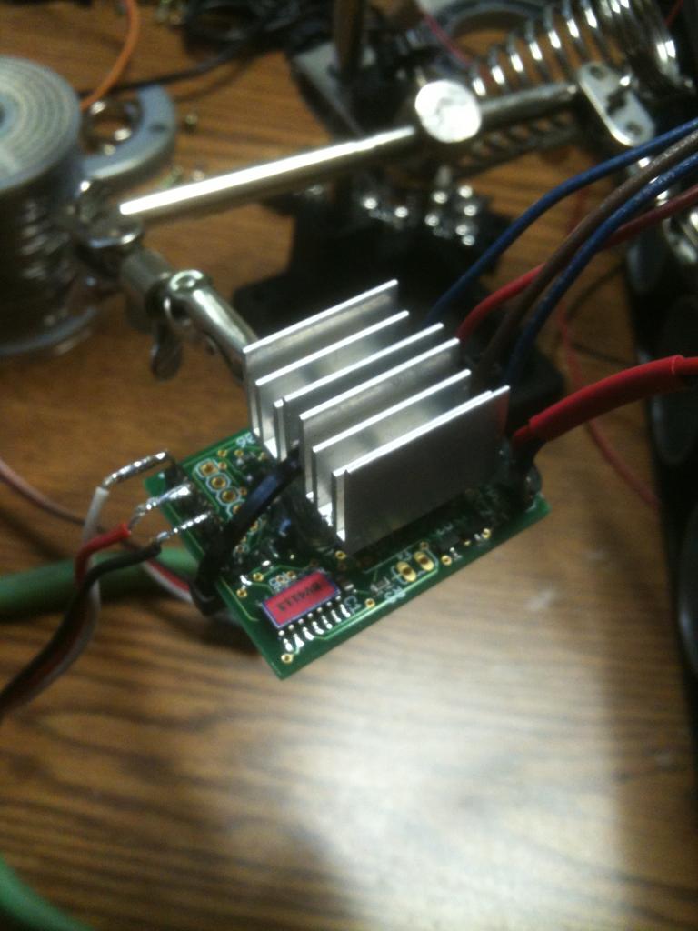
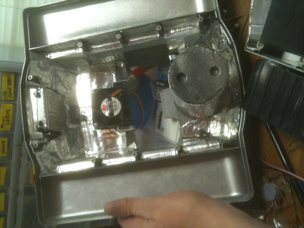
Thanks Josh - I'll try it first. I'm going to mount it and the fan tonight. I may also go ahead and hook up the EZ-B to see how it moves and how quiet it is. Here it is with my jumbo heat sink on it, and I will use your fan to help keep it cool. I have wired the fan directly to the power supply from the battery to the motor controller so the fan is on when the bot is on. However, as I want to have him in a sentry mode I may want to change that.
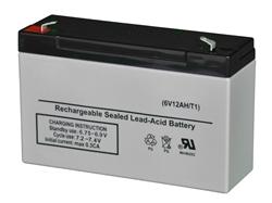
That fan draws so little that a 7 ah battery would run it for a couple days no problem. I.think your good on.that , however the only other option I can think of is to someway wire it to come on whenever a motor is running. I don't have any good ideas how to do that though. Just keep it simple man
I may have a DIO set for fans and just tie all of them to that one switching transistor. That way I can control all my cooling fans with either on or off. I'll have to look at what I have assigned. I may just leave it if it is not too large a drain on the battery. I do have 12 amps to play with from my new battery.
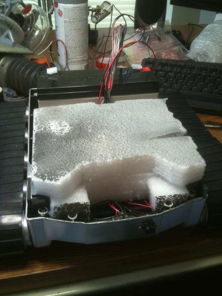
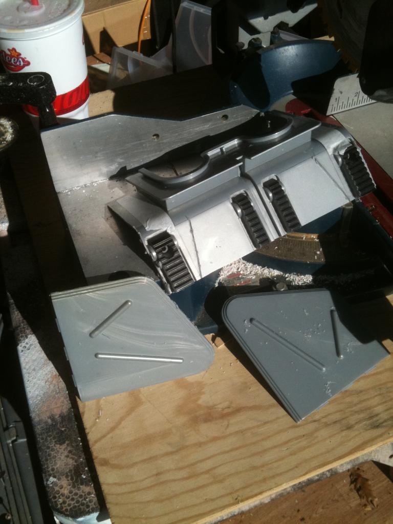
Mounted my motor controller and fan.
.05 amps , so a 1ah battery would power it for 20 hours , 12 ah is 240 hours runtime lol , unless you have a ton of fans it may not be worth the time to rig and program a switch from ezb.
Well, I already have a port designated for the fan on the EZ-B so it won't take away from my usage to tie the two together. And I like the idea of being able to control them at whim or with script. This little fan is also situated to help keep the battery cool - I like that as well. The old speaker mount is just above this fan and above that is a rectangular hole in the back that housed the old switches - I am going to put a mesh grill over that (like the one on front of Bob) so I should get good airflow.
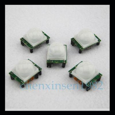
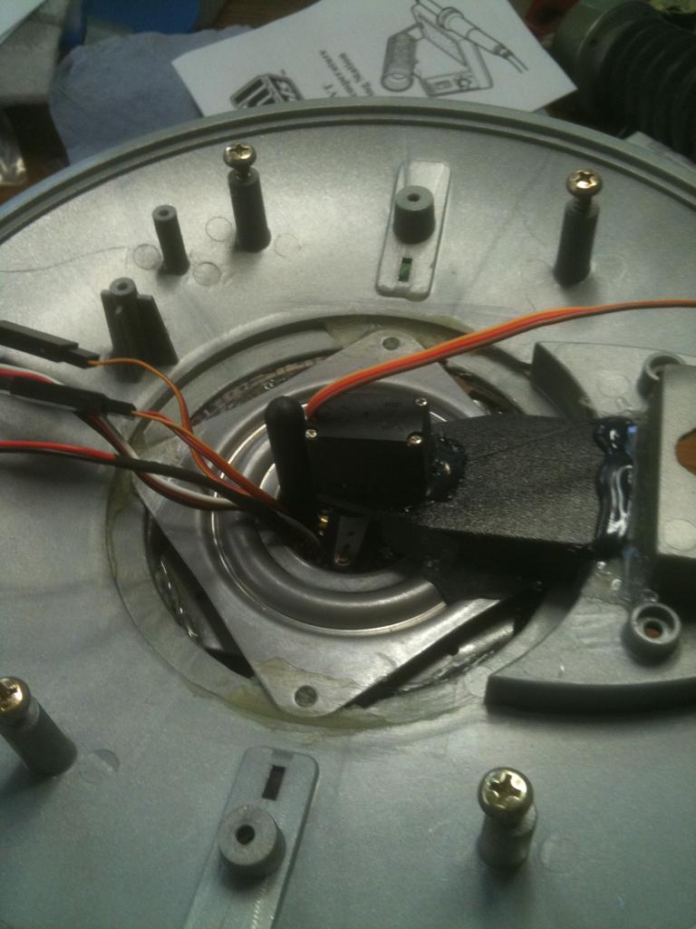
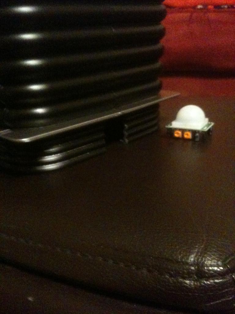
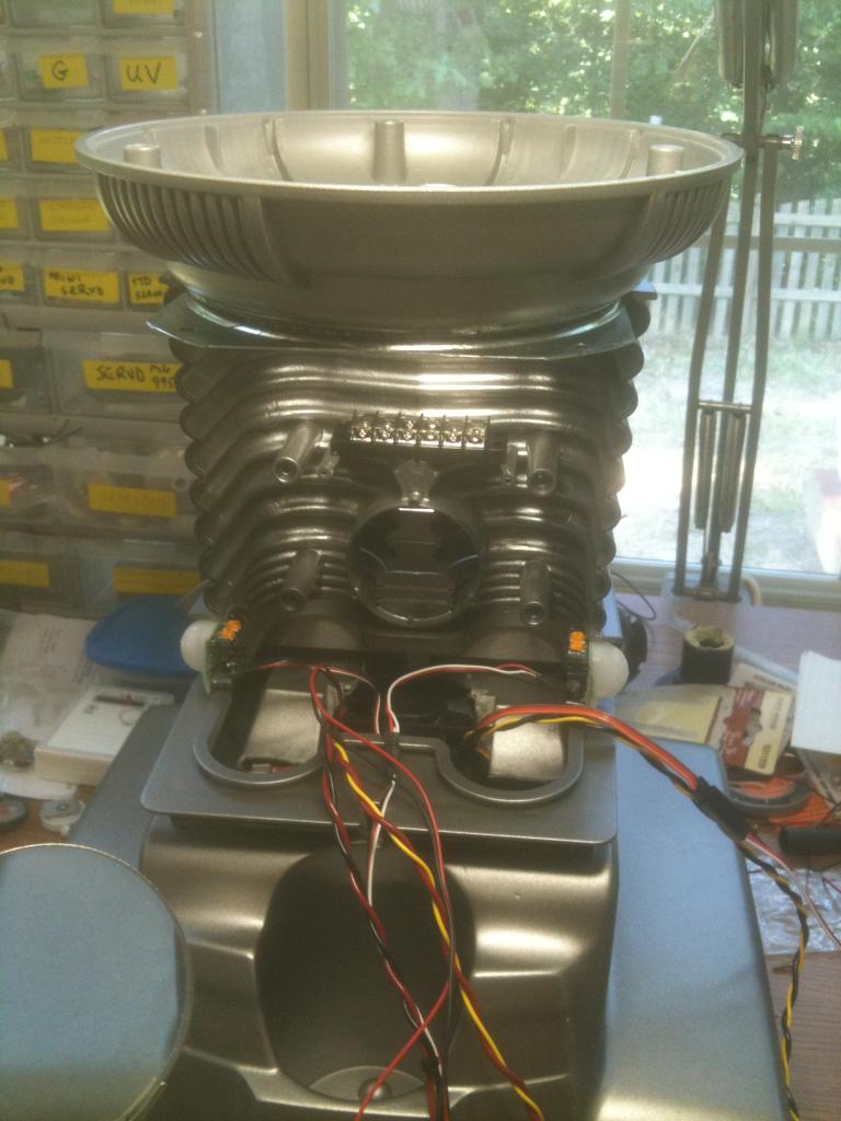
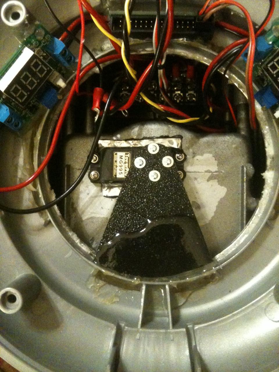
I mounted my lazy susan bearing to the legs last night and should start mounting the leg section tonight. Along with a terminal block, PIR sensors, and torso rotation servo. Then the base will be complete and I can concentrate on the torso and "head".
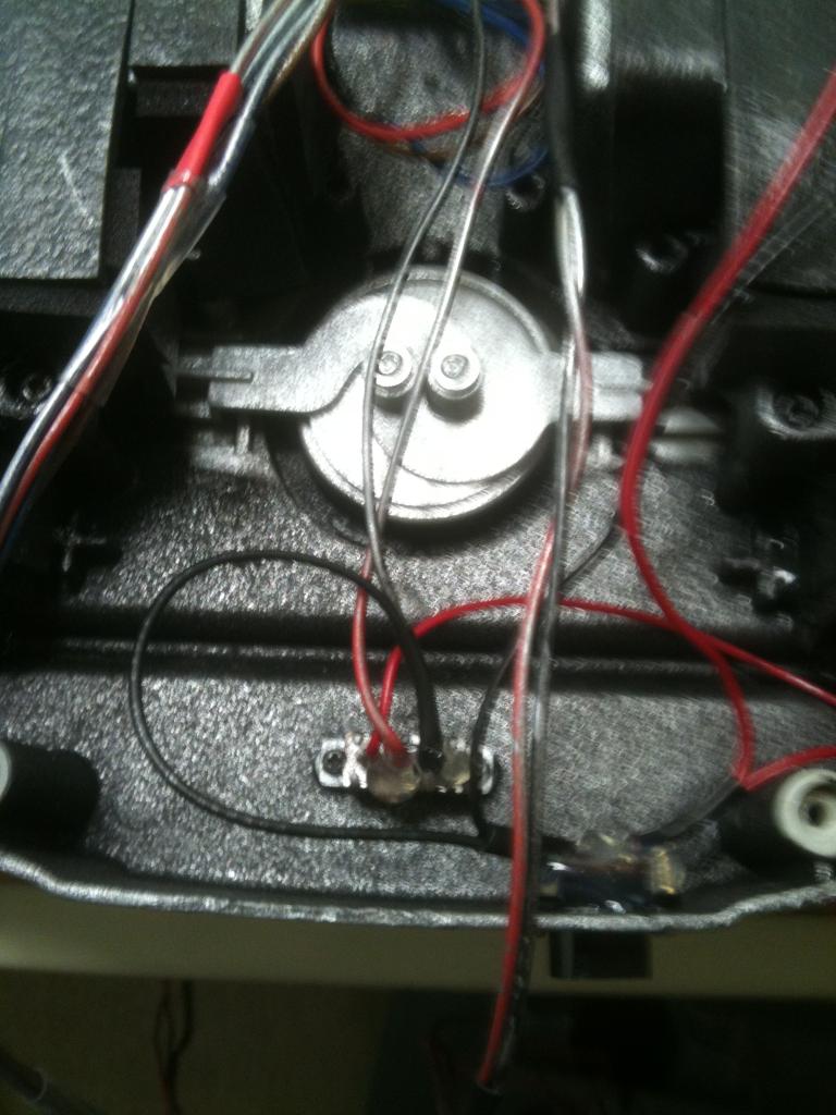
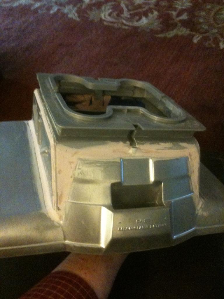
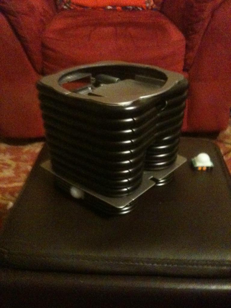
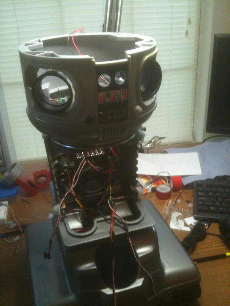
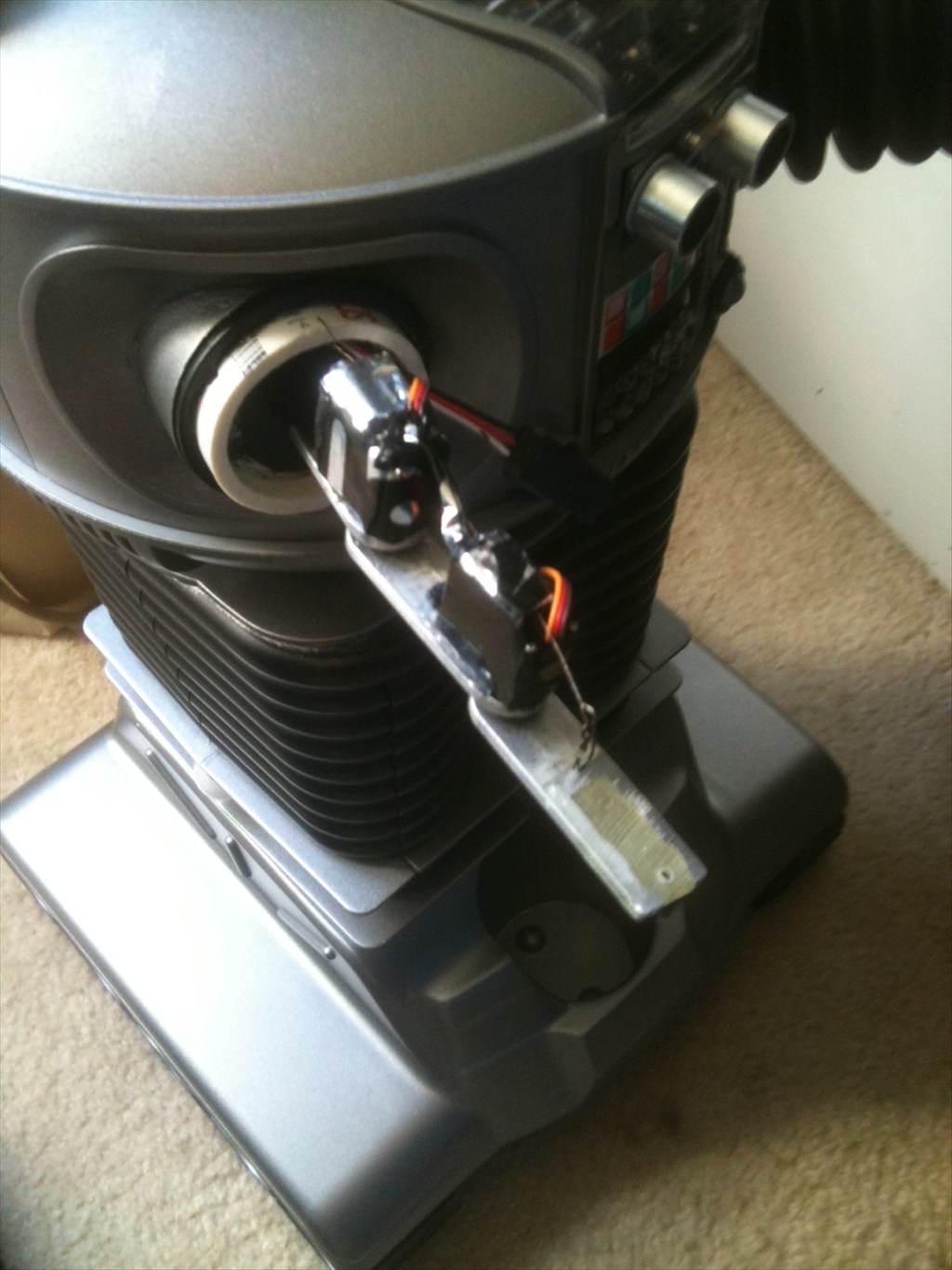
So here is the bottom half of B9. The lower part of the torso is mounted to a lazy susan bearing.

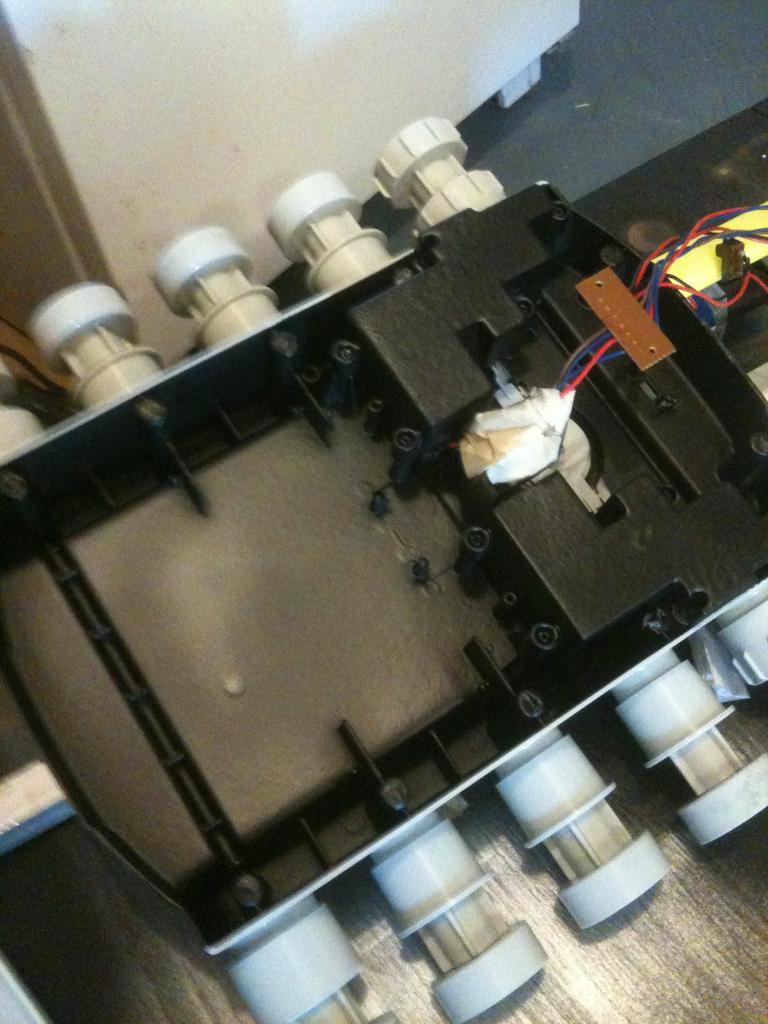
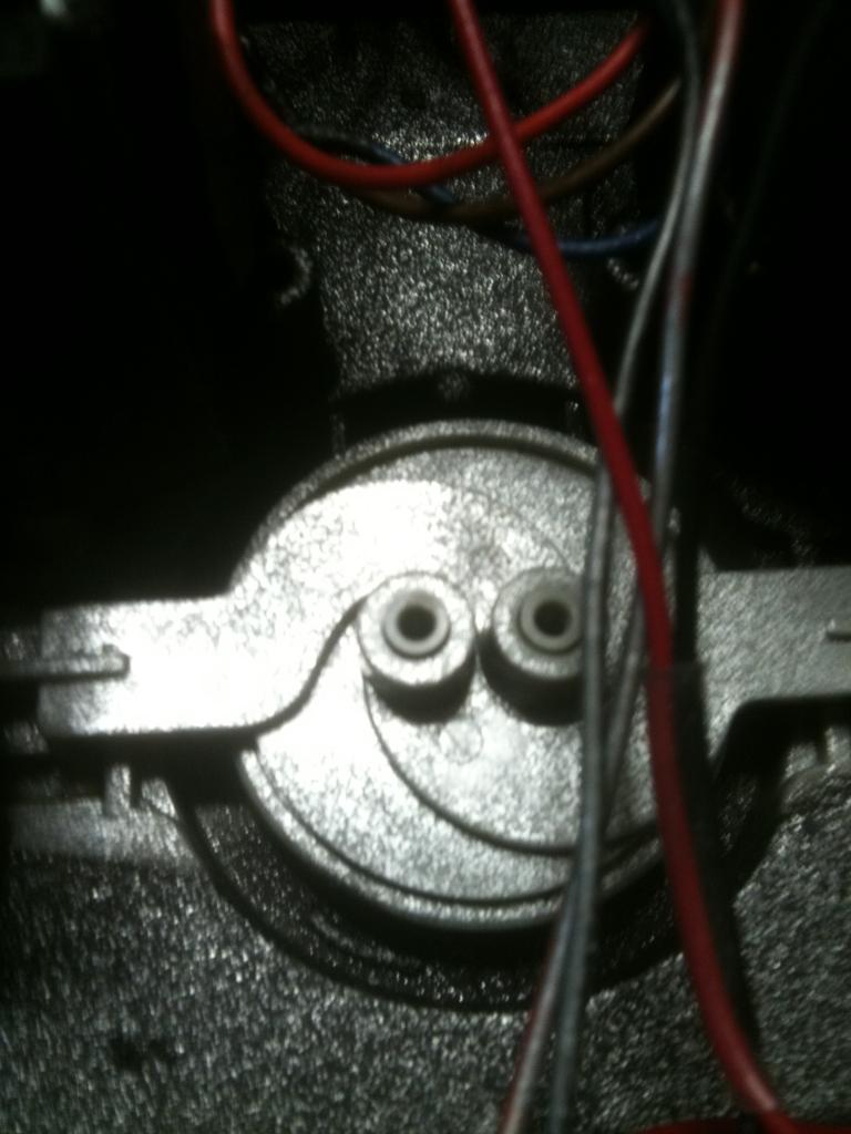
Note the PIR sensors in the "knee joints" - the little white spheres:-634709695807265625.jpg)
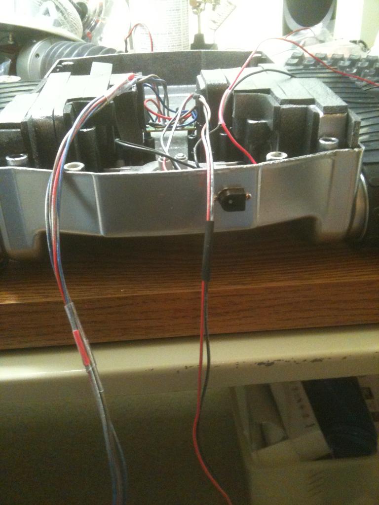
And in the back I have replaced the original switch assembly with wire mesh for air flow.-634709696076181640.jpg)
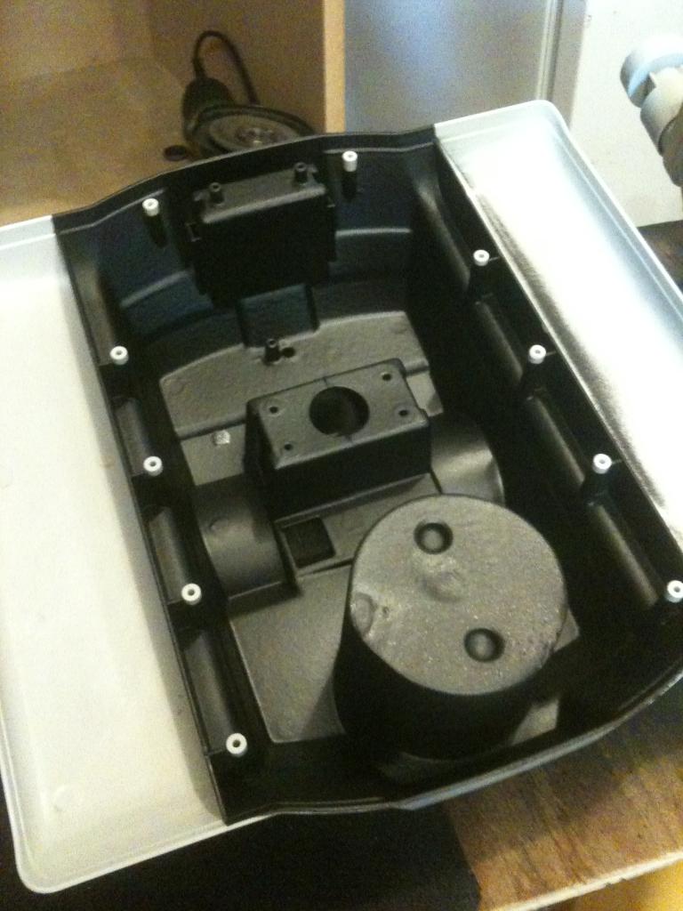
In the front is a door that opens up where the EZ-B is mounted.