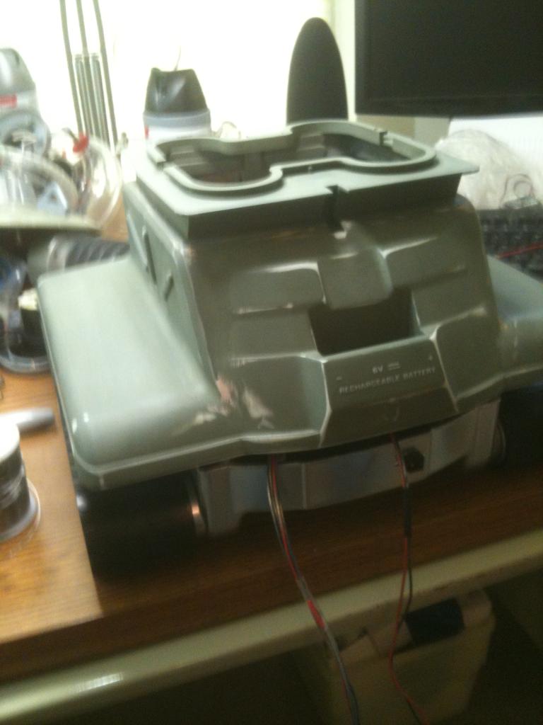
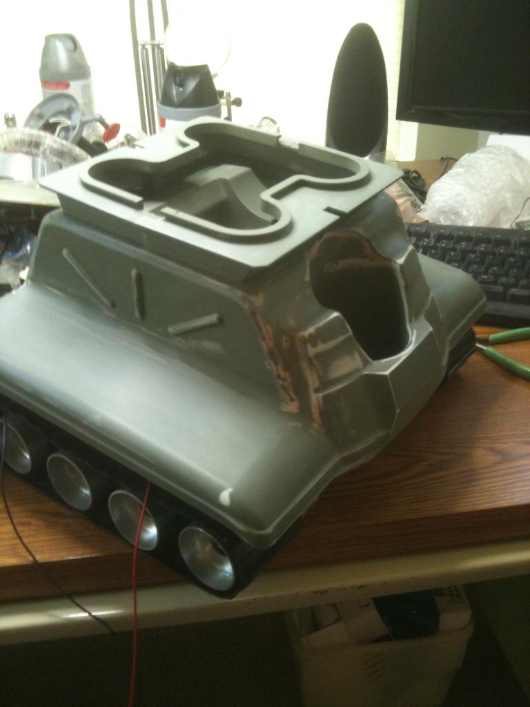
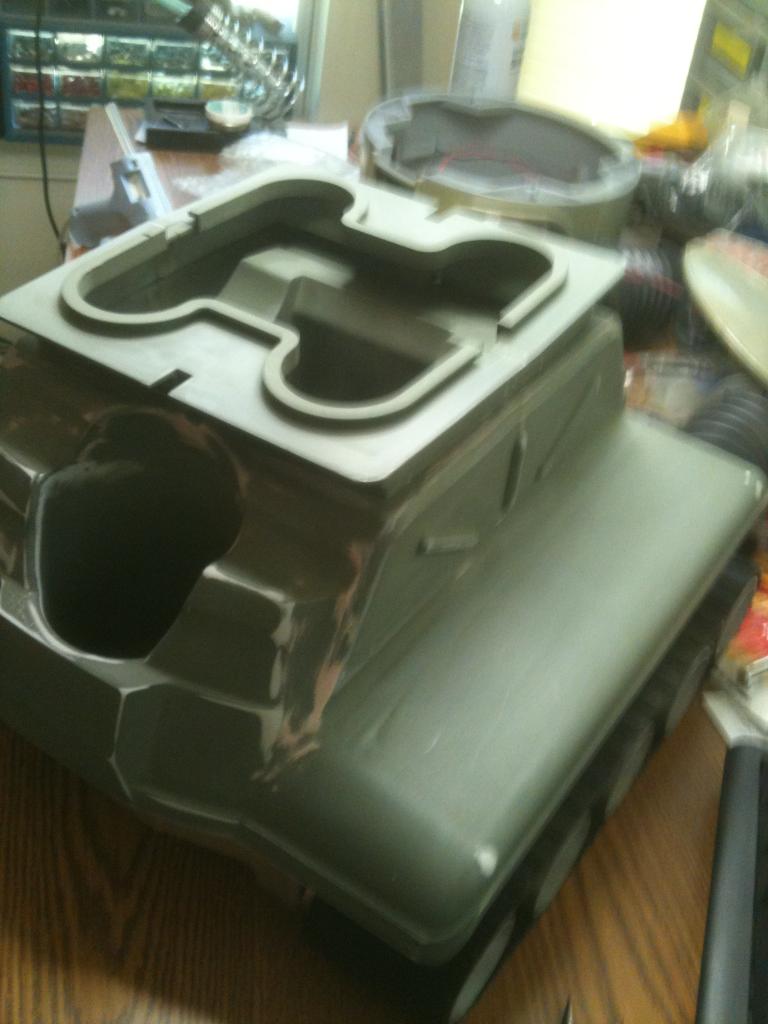
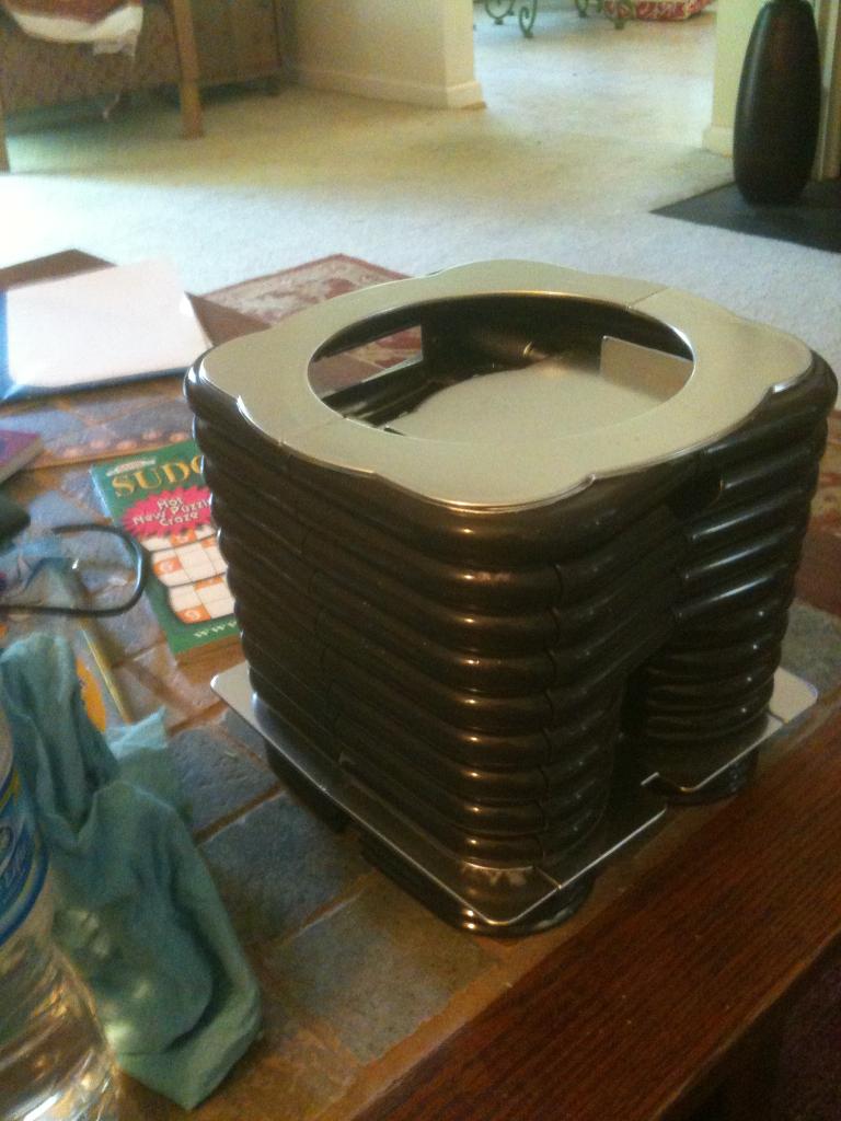
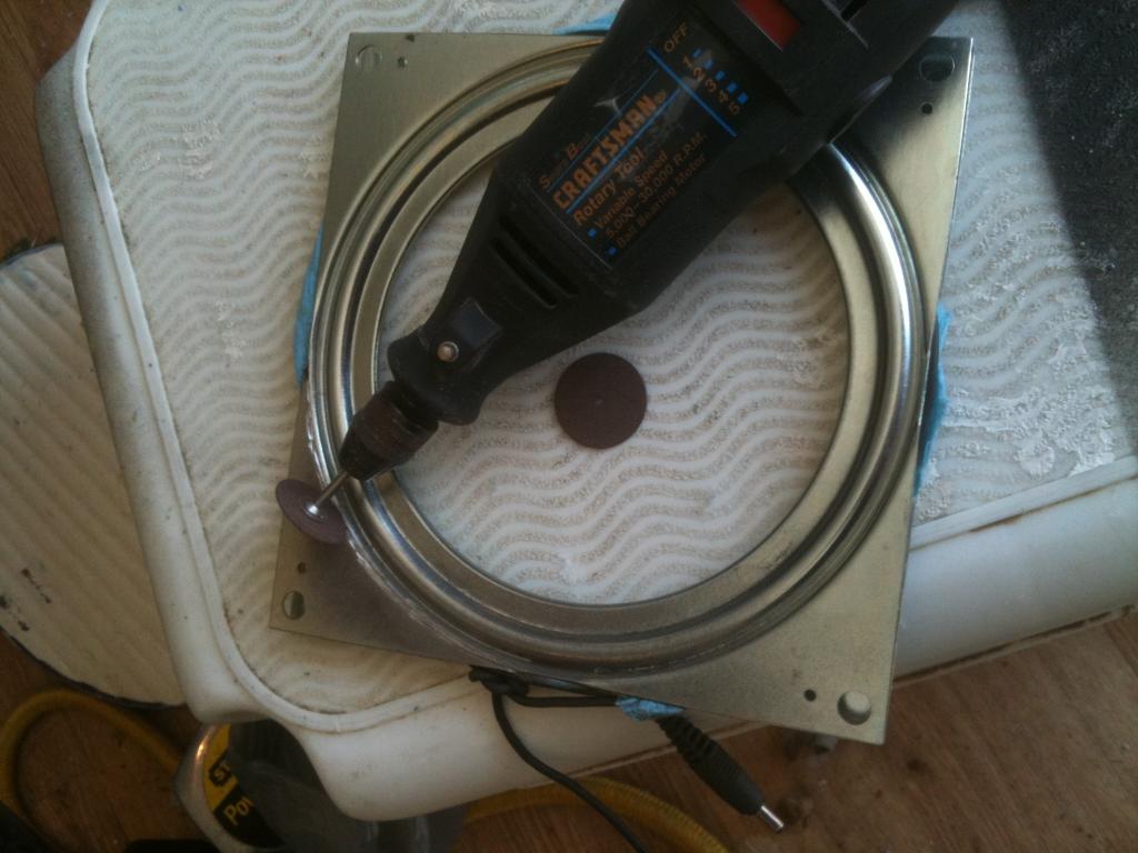
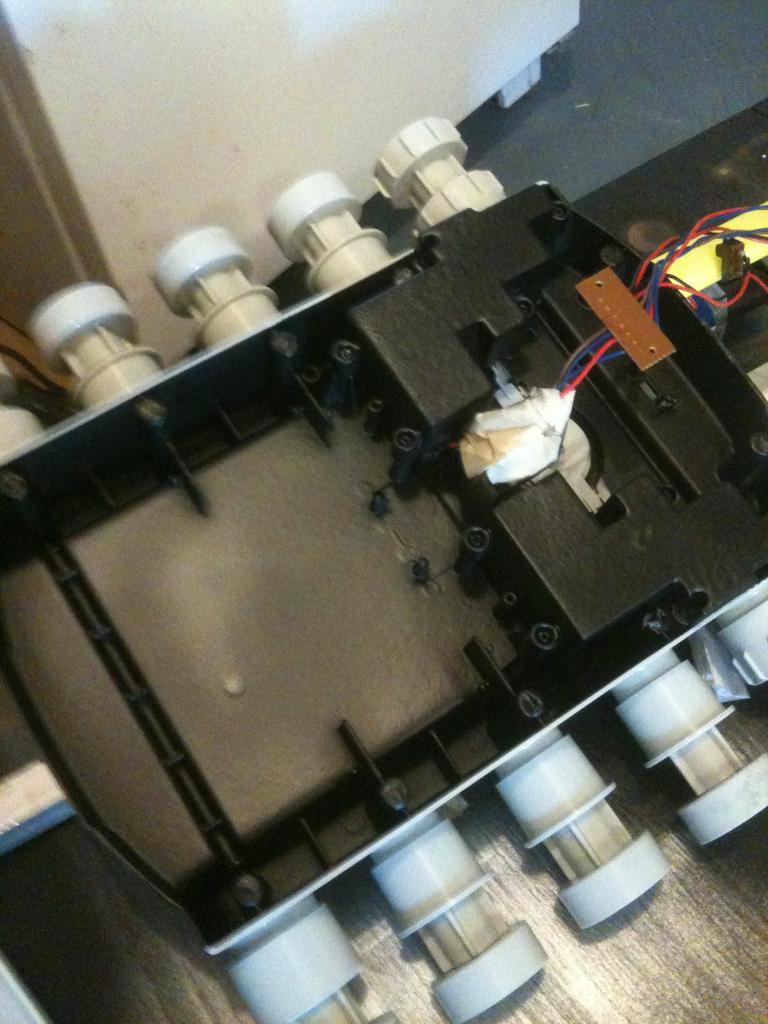
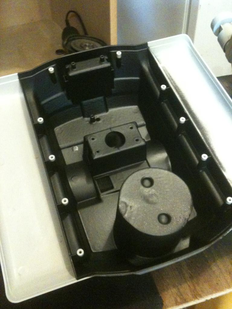
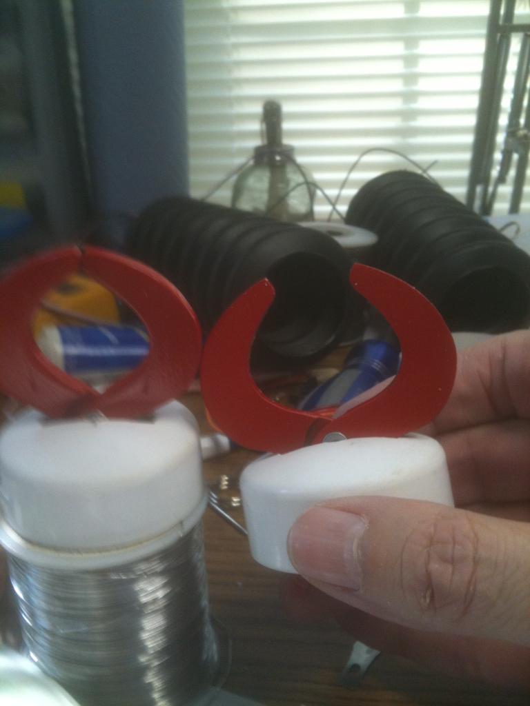
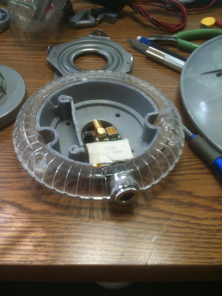
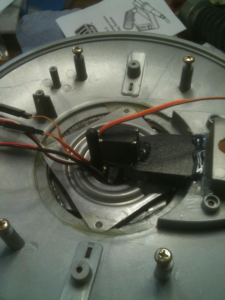
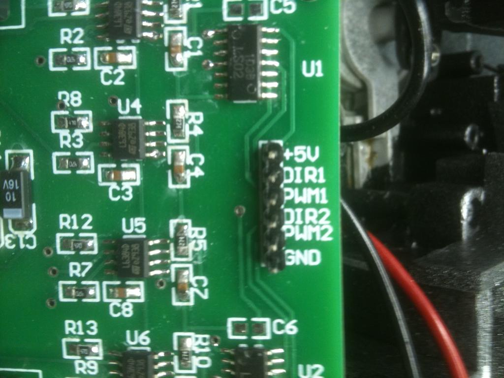
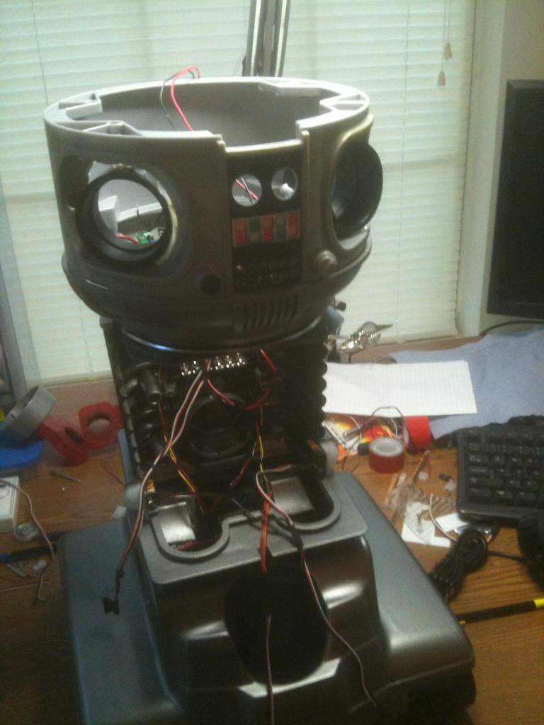
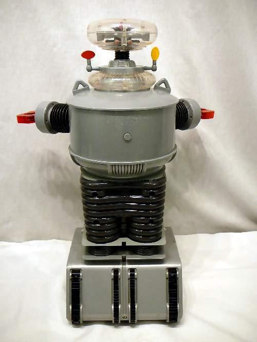
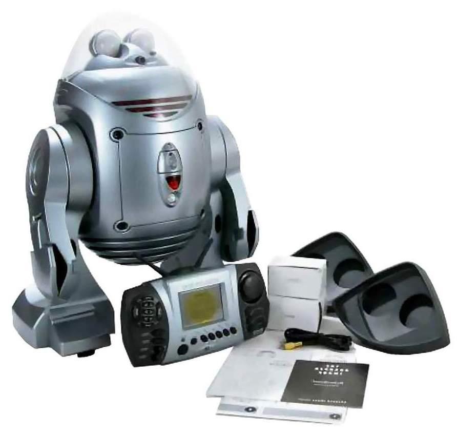
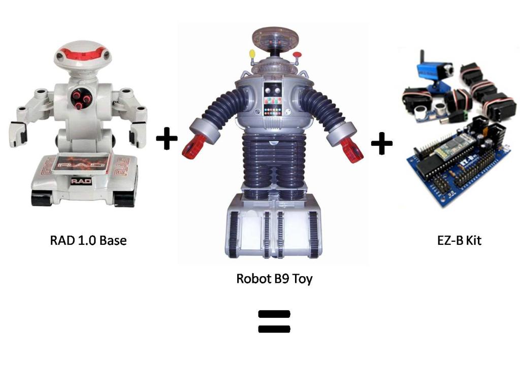
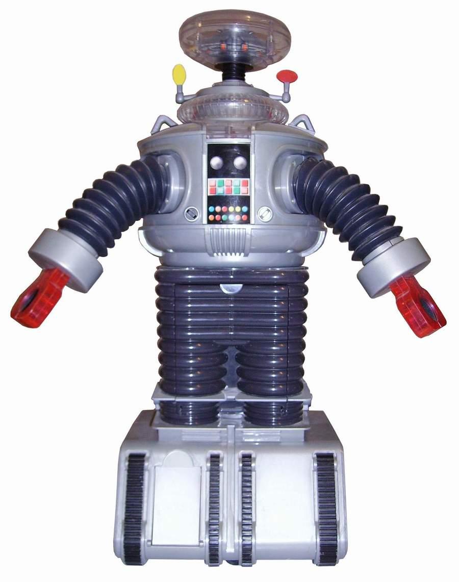
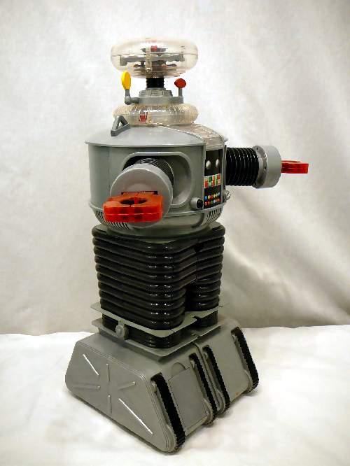
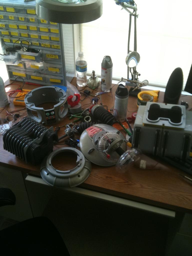
Now that I have finished B.O.B., my get your feet wet bot, I have begun my next hack. This next robot will bridge the gap between Bob and my ultimate big robot. I am starting with a remote controlled B9 toy from Trendmasters. It was very limited in what it did, and the drive section was pathetic, but it was B9!
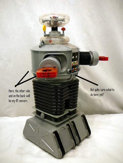
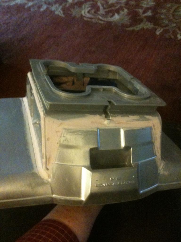
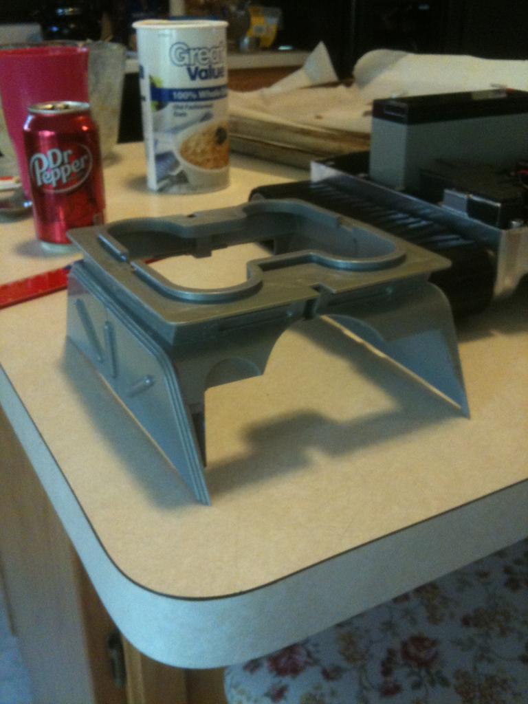
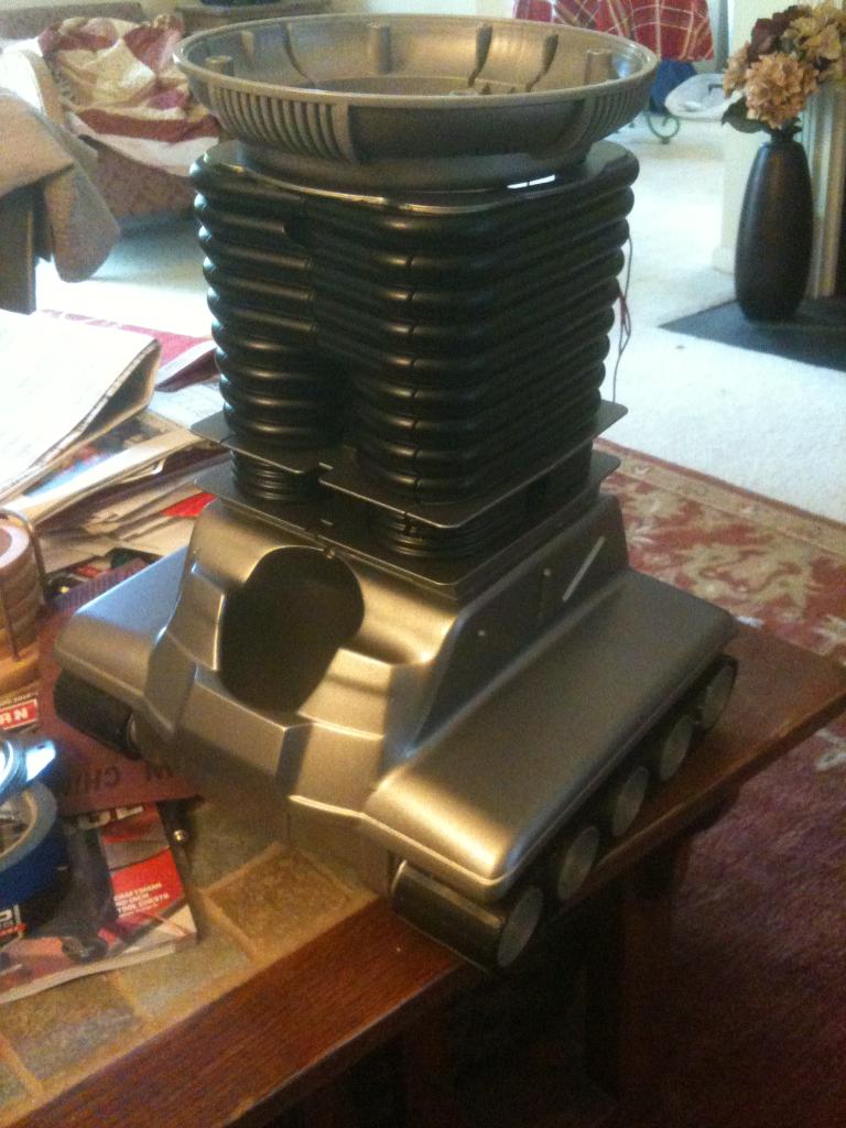
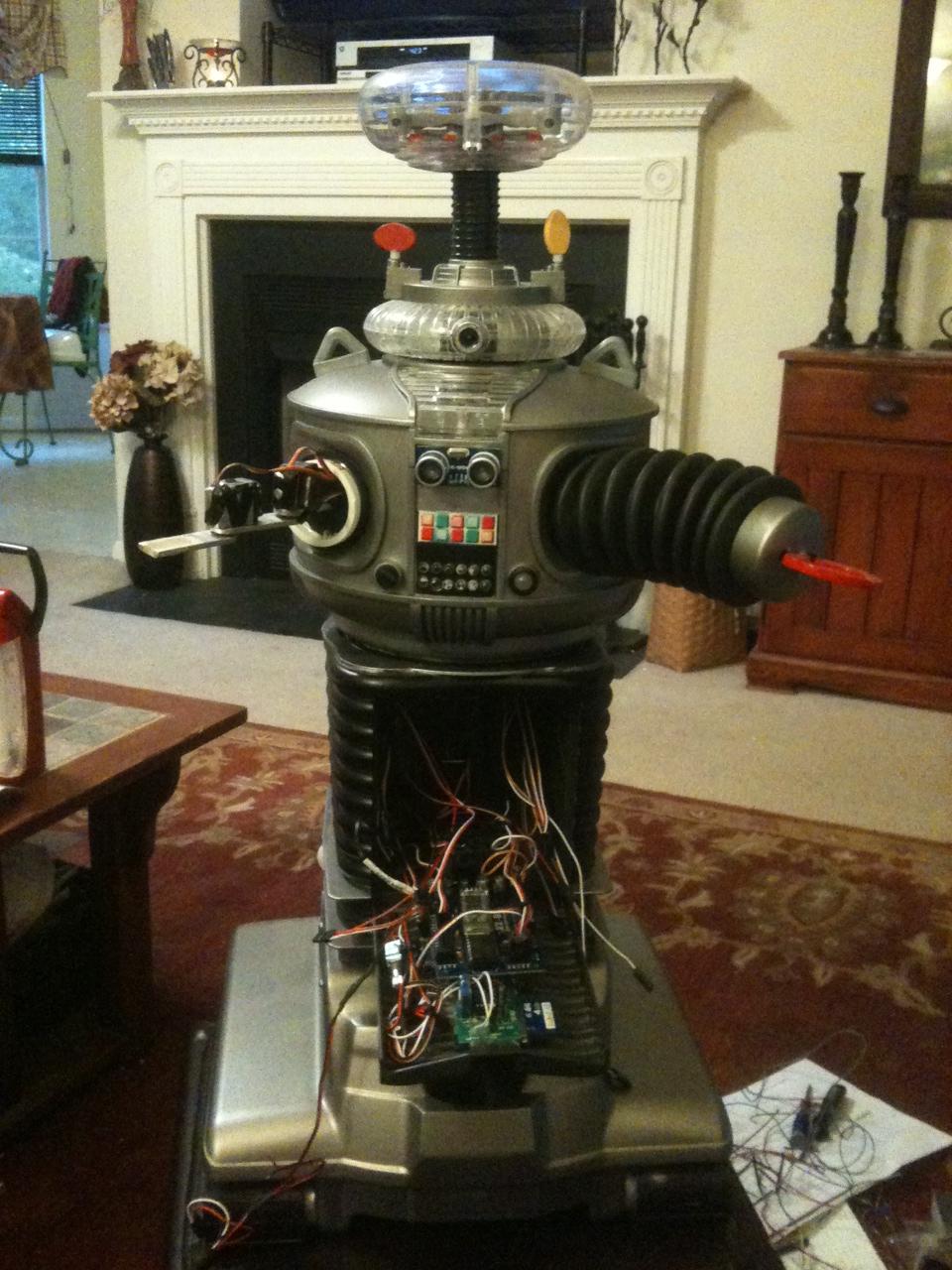
Before Pics:
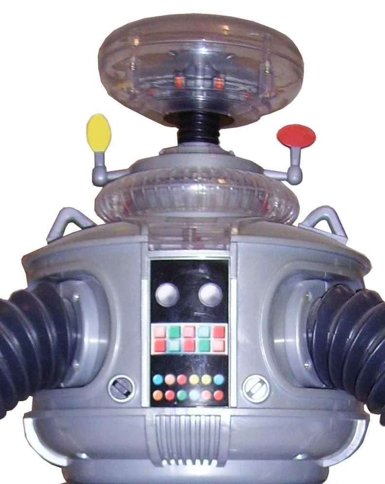
Note: the front "lights" in the chest plate is actually just a decal.
Here is what B9 looks like now:
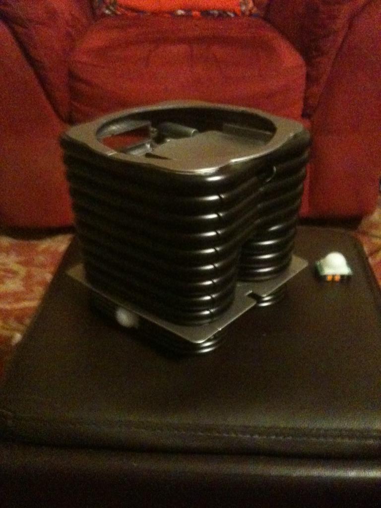
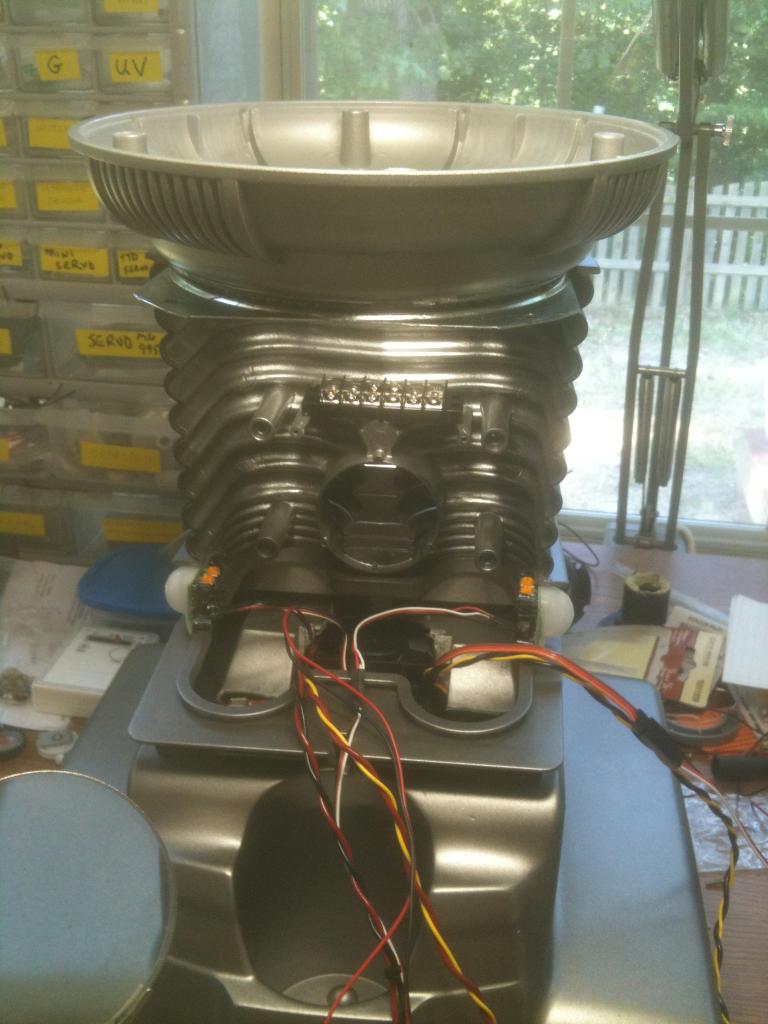
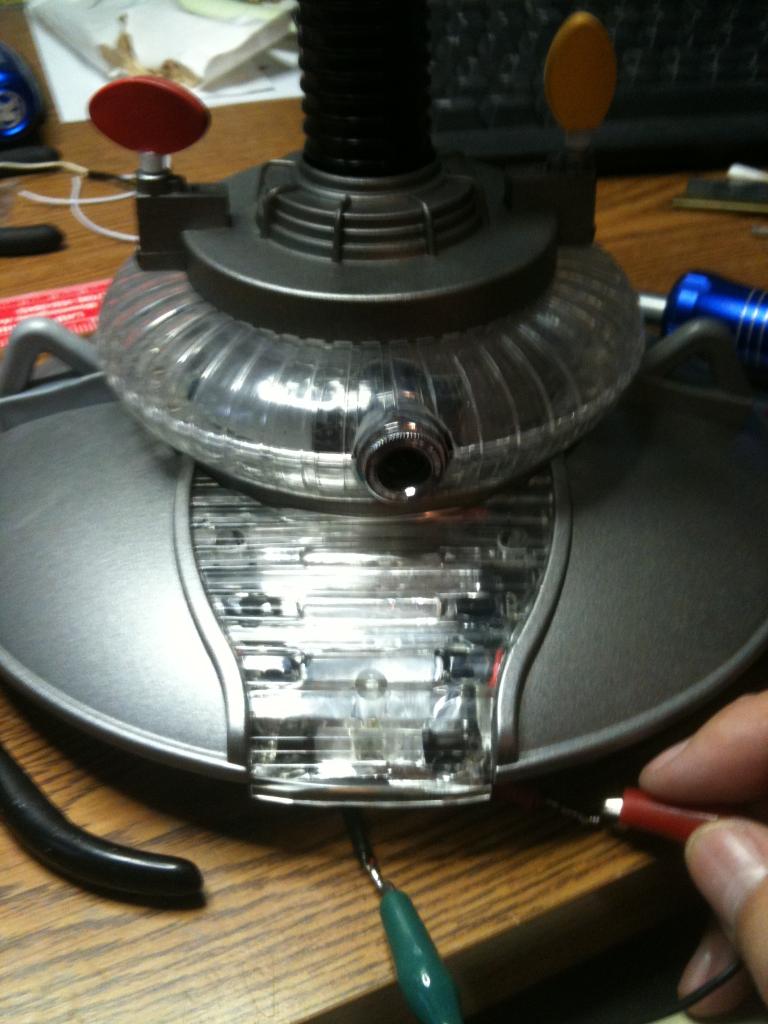
I have mounted clear LEDs in the appropriate colors in the chest at the bottom of the decal and have a flashing circuit that will blink them in the combination as seen on the series. Where the two large round circles are (white domes on the big guy) I will have my ping sensor. I have mounted pager motors in the antenna housings to turn the "sensors" as seen in the TV version. I have mounted red El Wire to his voice plate to emulate the original as well. I have also mounted a series of blinking LEDs to the "brain" section in the bubble.
Next is to work on the rotation of the bubble and torso, articulate the arms and claws, and make a real functioning tread section. For the tread section I am adapting the base from my RAD robot. I will keep you posted with pics as I proceed.
Thanks,
Bret
Other robots from Synthiam community

Jstarne1's Levi Rover Modular Robot 3D Print

Jstarne1's Diy Awesome Project Case Made From Netgear...

They got him back together though. I am sure that you will too. I look forward to seeing him moving around on his own.
I have a 5 and 1/2" acrylic lazy susan bearing coming in so I can rotate the waste, and a servo attached to the bubble's neck will rotate that. But I will have to do some cutting to the bot to get the collar section to rotate, but that is where I want to mount the camera. I'll have to see what I can do there. I also have a plan to get a fairly full range of movement out of the arms that will mimic the original robot from the series.
After it all dries well, then I'll get the motor controller and batteries set up. I plan on using the original wiring in the base, along with the on/off switch. I will also mount my charging port here in the base. I plan on two 6V batteries wired to keep it 6V but increase the amps. This should give me a longer run time.
That is looking great! I am curious to hear how your undercoating went...how many coats did you use and where did you get it?
Again....B9 is looking pretty sweet!
v/r
Kevin
The dimensions are 6" X 2" X 3.7" (LxWxH) - it is 6V 12AH and only $14.00
@jstarne1 - what are your plans for your RAD base?
And the battery:
Then I have the B9 base I need to blend with it so the leg section can attach.
It's a rover.5 smaller footprint. 9.5 inches should fit.under your b9 without hanging.out. its 45 bucks , 4 motors , adjustable track length too. It's the.rover 5
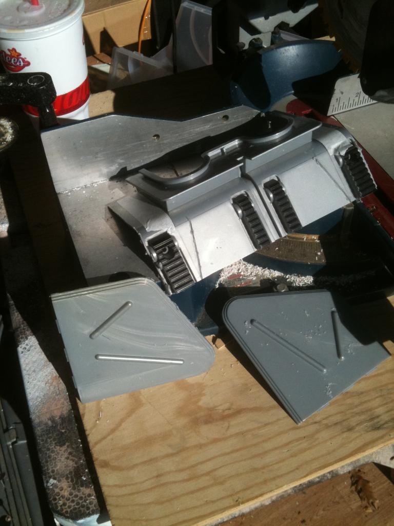
Then I needed to cut out section to fit over the hump in the RAD base.
Then I had to shorten the side panels and give them a slight curve to match the contours of RAD
Next I need put all the B9 pieces back together and mount it onto the RAD base with plastic epoxy.
I think it is looking great.....well done mod. I like how the RAD tracks set outside the B9 base, I like to see the tracks moving ..personal preference....it will go together nicely It easy to start sinking big bucks into this stuff..
v/r
Kevin
And here is what it looks like sitting on the RAD drive section - note I can still use my cup holder. Yay!
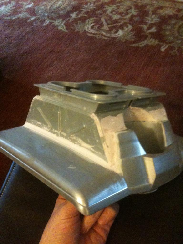
...and sanding...and sanding
...and then sanding some more. I should put on my last skim coat this weekend and get all the sanding done. Then I can paint it and complete the drive section.
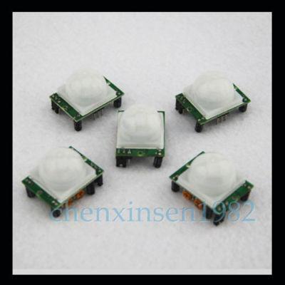
100% BRAND NEW!
Weight: 33g (approx)
Color: White + Green
Dimension: 3.2cm x 2.4cm x 1.8cm (approx)
Infrared sensor with control circuit board
The sensitivity and holding time can be adjusted
Working Voltage Range: DC 4.5V- 20V
Current drain:<60uA
Voltage Output: High/Low level signal:3.3V TTL output
Detection distance: 3--7M(can be adjusted)
Detection range: <140
Delay time: 5-200S(can be adjusted, default 5s +-3%)
Blockade time: 2.5 S (default)
Trigger: L: Non-repeatable trigger H: Repeat Trigger (default)
Work temperature:-20-+80C
Trigger Method: L unrepeatable trigger / H repeatable trigger
Note:
Sensitive Setting: turn to right, distance increases (About 7M); turn to left, distance reduce (About 3M)
Time Setting: turn to right, time increases (About 300S); turn to left, time reduce (About 5S).
Package Included:
5x IR Detector Module
And I think I will mount 3 of them in his lower torso on the sides and back - nothing gets past B9...
You're a freaking Genius!!!!:) Always Great Advice!
@brett I don't know if you ever done this but get warm water , put some dishsoap in it , like dawn. Just so it is a little soapy. Dip your sandpaper in it every minute or two its way less messy than all the dust. I do mine over.the.kitchen sink. You will see it sands much easier with less resistance , easier on your fingers
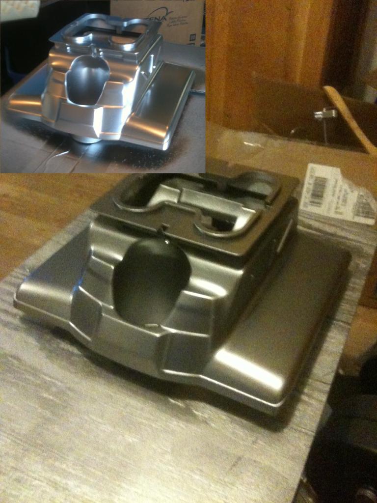
Thanks to input from jstarne1 I have primed and water sanded the newly melded bases of B9 and RAD. It is not perfect, but good enough for paint (for me anyway).
And here is the leg section with new paint - I still have to clean off the silver that worked its way under the tape, but I like the color.
great job of joining the two robots together . It looks like they were moulded that way .
A fantastic job .
Steve_c
I had to quieten up a genarator on my boat , I put sound deadening tiles around the inside of it box and
poly foam under the lid , It was alot quieter .
Thats what youve done there so it will be much better.
Steve_c
After some good dry time I am going to give it a coat of carnuba wax to protect it and then mount it to the drive section. Then comes the leg section and some more wiring of sensors, motor controller, and install of the EZ-B.
First I cut it down to fit the torso base.
Here it is trimmed up to fit the leg section - it will be mounted under rather on top.
Now the torso base fits it well.
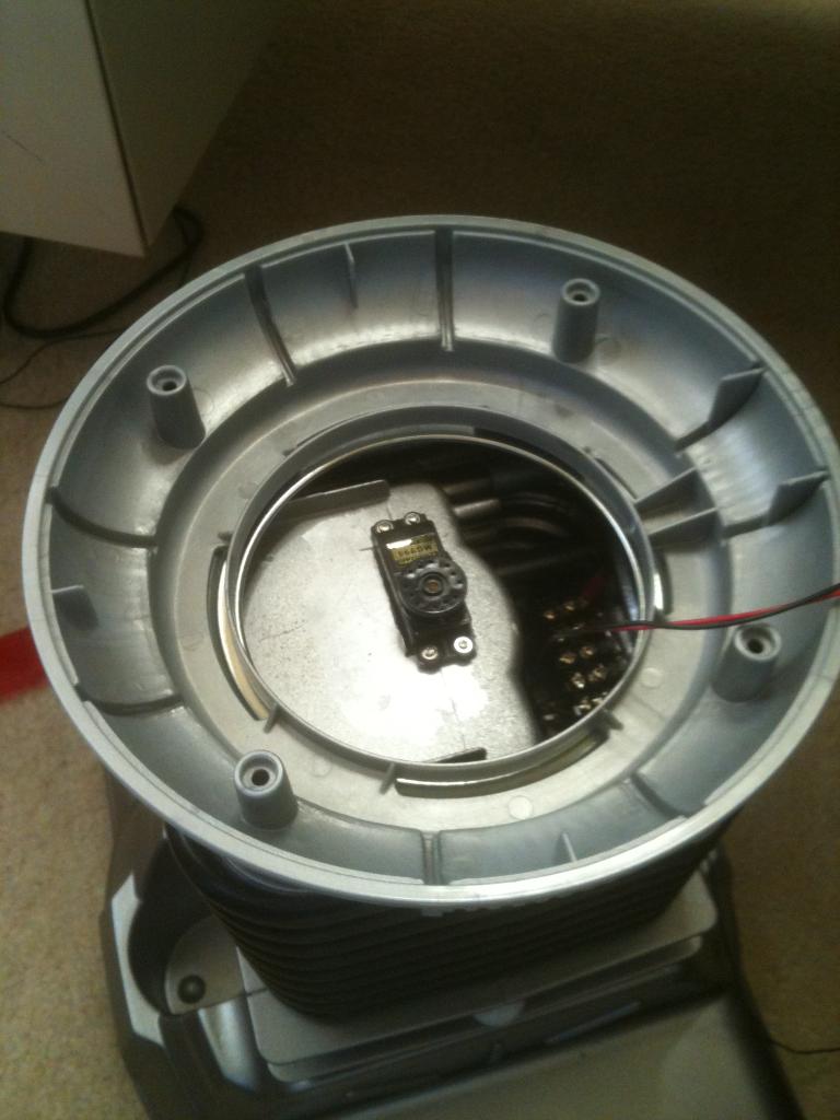
And there is a perfect mounting place in the leg section for the servo that rotates the torso.
In the upper corner is the silver I started with, and the larger image is what I will be going with.
Then I will put a top coat of clear satin finish to protect it and take some of that gloss off.
You could put a wheel on a servo , and make a lip/ ring and glue it inside the body. Mount the servo and wheel agianst the ring and that can control left and right motion and no gears to strip incase it runs into a table or falls over , just center it back and keep going. Much like in the pic the tire is agianst the ring on this carnival machine. No belts to break no gears to strip.....
You can snug the wheel on any edge , top , bottom , or like I have pictured on the inside :). Be sure to use a metal gear servo though
How do you maintain position of the torso with regard to the servo position in this configuration? Because of wiring I can't have a continuous rotation servo. But a 270 degree servo might be nice.
360 servo
like this
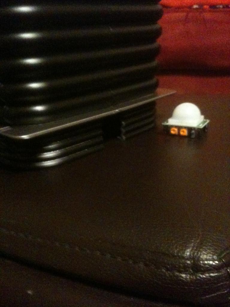
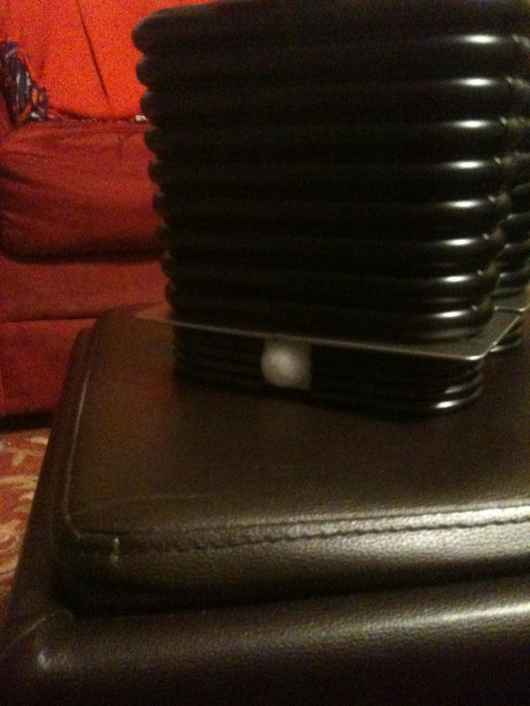
I enlarged the cut out in the side (originally there was a silver "knee" joint here) to mount my PIR sensors.
They fit very nicely and will sit about a foot off the floor on each side.
To minimize port usage (as I am more than maxed out and in need of cutting a few things back) I am going to use a single port to activate both sensors when needed (sentry mode) and tie their outputs to a separate voice module from an old B9 toy so it will say either "Danger, Danger Will Robinson!", or "My sensors indicate an intruder is present!" in a random order. This way I can still get the audio without the use of one additional port.
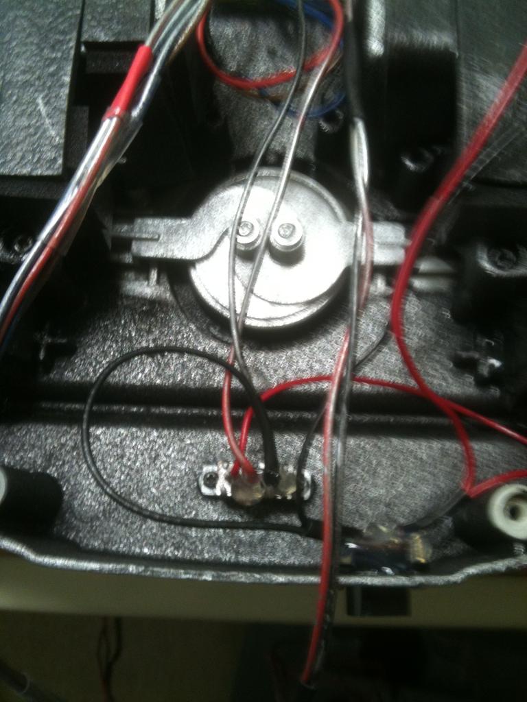
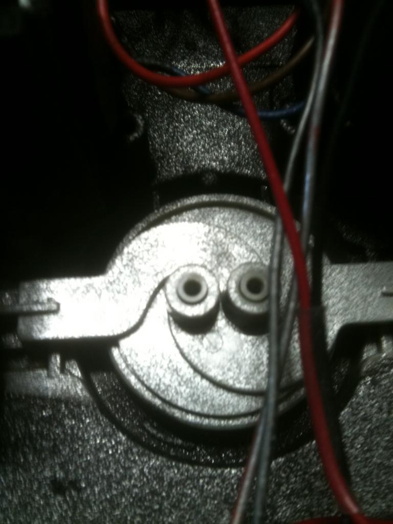
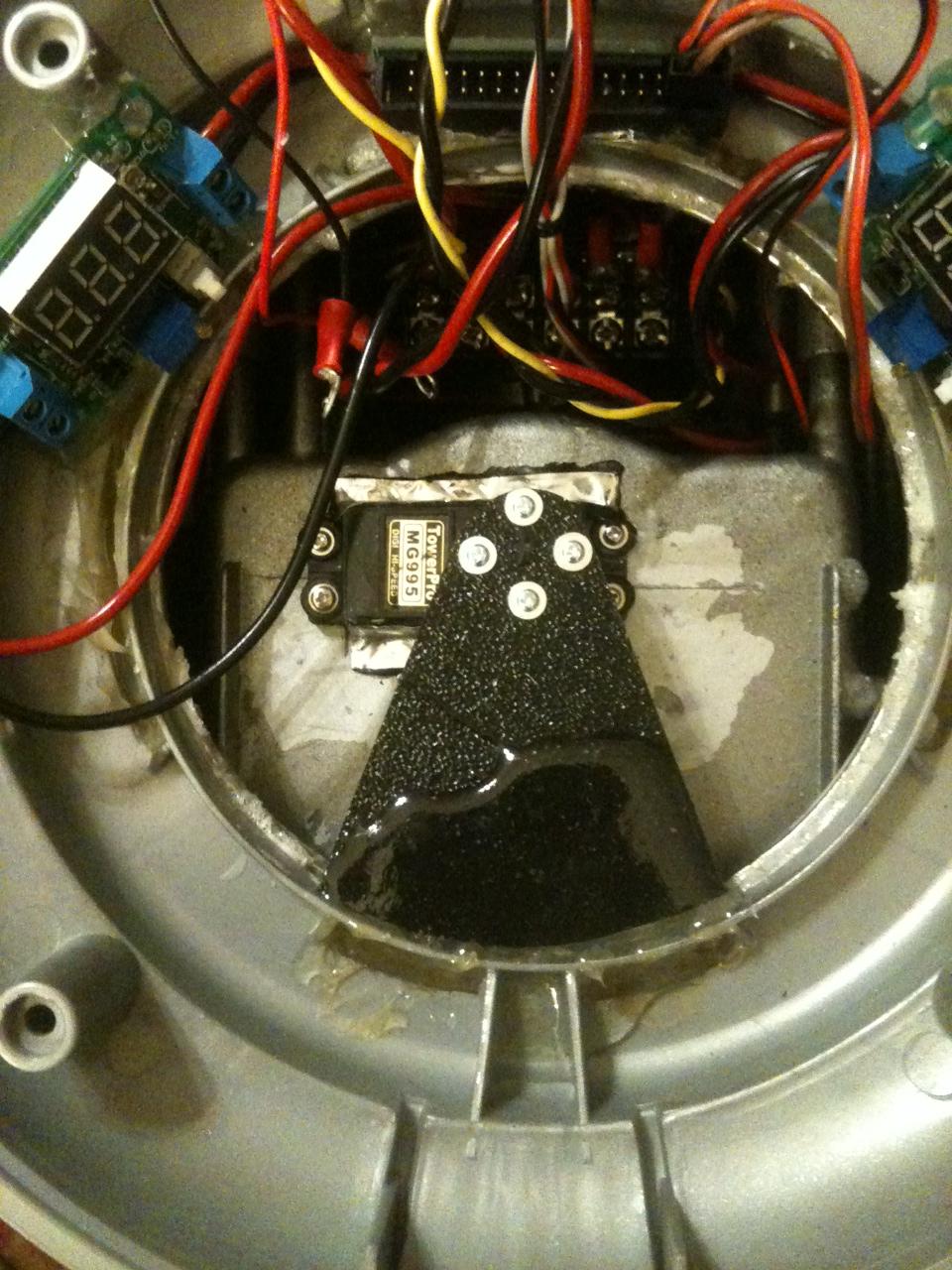
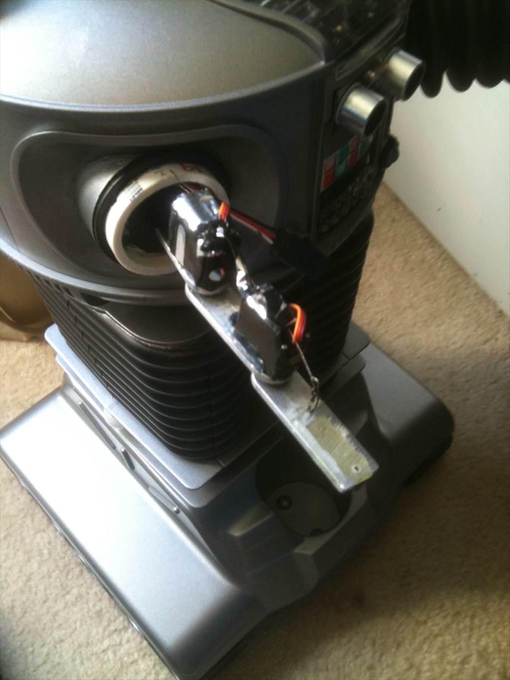
This is the mechanism from the inside of the base. I removed the two screws that hold those arms on.
Then I had to cut a piece of plastic to use as an adapter between the mechanism and the servo horn. This is because the screws on the mechanism are too close together to mount a servo horn directly to it.
With the servo horn on the servo, I am using rubber bushings as spacers.
Then I secure the servo to the adapter plate and compress the bushings as I tighten it down.
The servo sits between the motor housings and basically floats on the mechanism.
I then pack foam core around the servo which keeps it from rotating.
And Jimmy is ready to take it for a spin
@jstarne1 - Thanks man! Hey, go to All Electronics on line. I believe they have the motors you need for your arms.
linky
I seriously wonder if this motor controller is going to work for me, or I need a larger one?
I mounted my lazy susan bearing to the legs last night and should start mounting the leg section tonight. Along with a terminal block, PIR sensors, and torso rotation servo. Then the base will be complete and I can concentrate on the torso and "head".
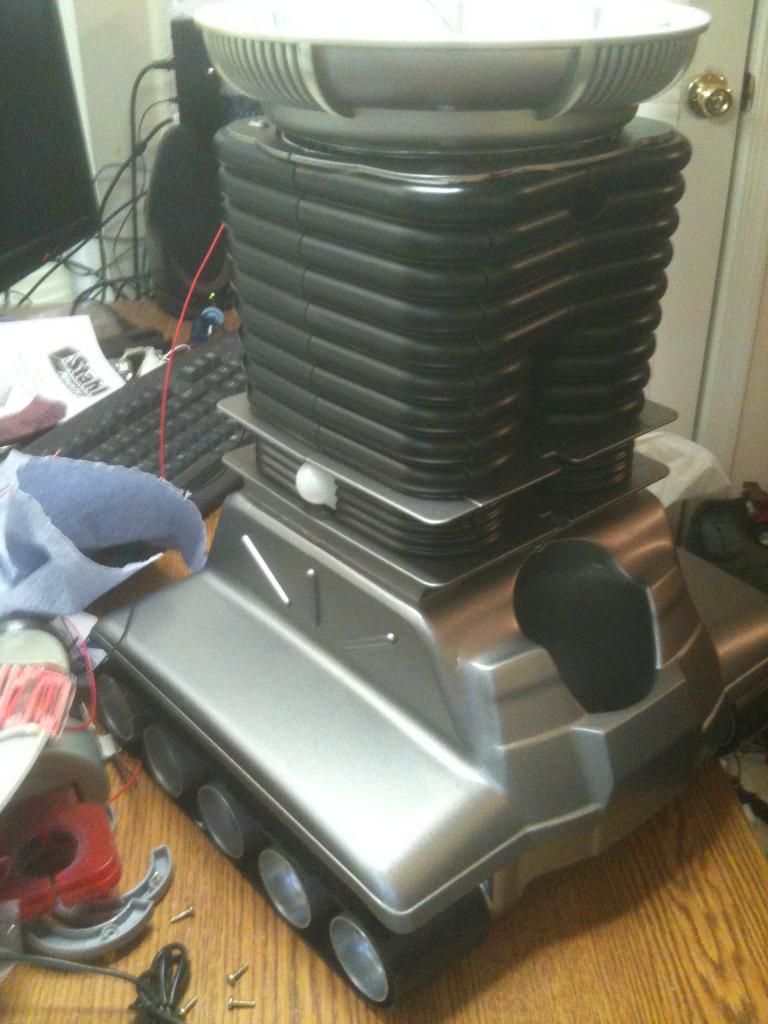
Note the PIR sensors in the "knee joints" - the little white spheres:
And in the back I have replaced the original switch assembly with wire mesh for air flow.
In the front is a door that opens up where the EZ-B is mounted.
Wow! Playing catch up on the forum...you are really moving out on your bot. It looks really, really good!
Nice work!
v/r
kevin
Brett - its looking good , I love how the rad base became one with your b9 so well :). I'm going to send you a light sensor , when I bought mine I got like 5 of them.
This is actually a storage compartment in the front of the leg section - part of the original bot.
I'm going to mount a triangular piece from the front of the torso base to the servo horn. That way I can get the rotation I want without damaging any of my wires. The storage compartment becomes the home for my EZ-B.
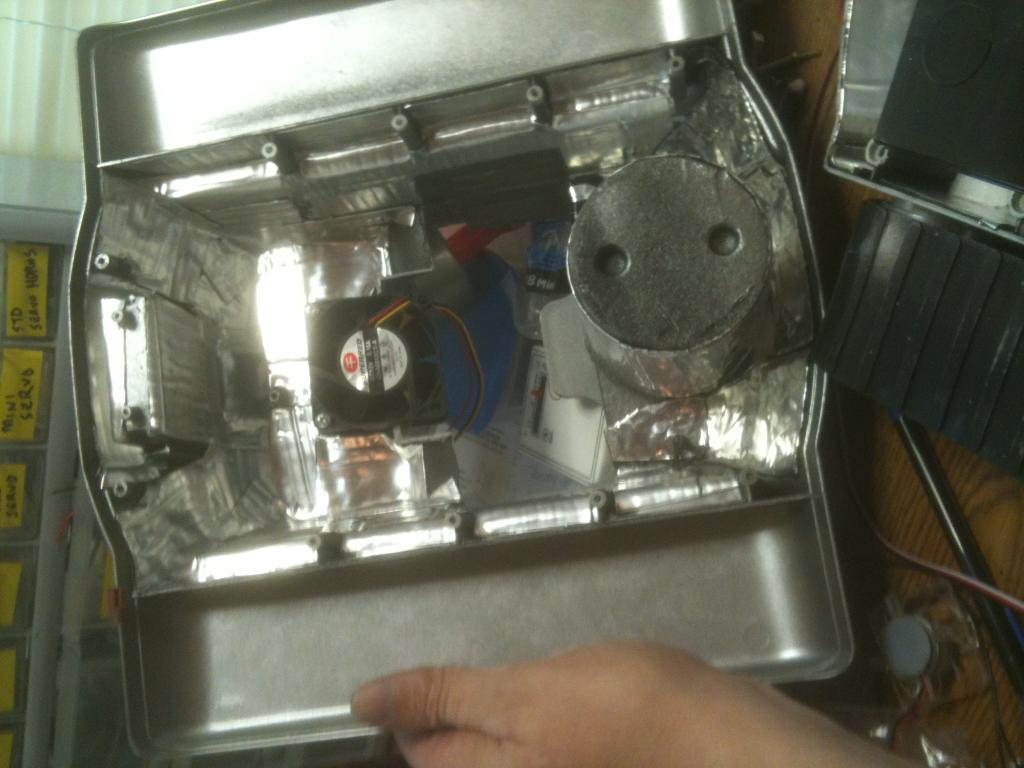
There is plenty of room in here for the EZ=B and easy access too. I have drilled vent holes to help the fan keep it cool and run my wires. Next step - install the EZ-B. Unfortunately for now it looks like I'm going to have to rob Peter to pay Paul so-to-speak (I'm going to take the board out of Bob for now).
I know what you mean about that..but you gotta do what you gotta do....B9 is looking very good.
I like the lillypad LEDs if you can work them in vice regular LEDs. I actually think they are brighter too but mounting them could be a challenge depending on where they are needed.
vr
Kevin
I have to say am not very happy with this. Not sure if I don't have enough power, the motor controller isn't up to snuff, or the motors are just too over loaded. THis is the low gear setting so the speed is not such an issue, but in high gear it wouldn't even move. I'll throw the charger on it to see if the battery is just low. If that's not it then I'll try a different motor controller. After that, the only thing left would be to change out the motors. We'll see....
As a RAD owner I run my motors at 7.2V (RC Car battery) and they do not sound or bog down like that. More juice I think.
v/r
Kevin
Take in mind this is about 3/4" longer than ezb , and with heatsinks wider too. I they claim 60amps peak , 10a continous so there's no way you could overload this ir damage it by stalling ect.
ESC 20A
I know they are listed in euros but they are coming from china and shouldn't be a problem. I have the pdf for these if you want a little more info.
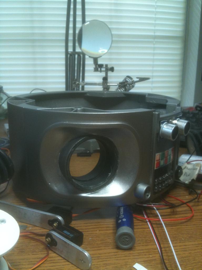
Then modify the collar and neck to house the camera.
I will use a lazy susan bearing to join the head back to the shoulders. The camera fits very well in the collar with just a little modification.
Not exact, but good enough for government work...
Now I can rotate the antenna just like his big brother.
And here is the head section with the camera, antennae, and bubble with lights. If you look close you can see some fiber optics coming out of the bottom. Next to mount this to the top section and test out the camera, head movement/tracking, and lights.
And here is the head/bubble mounted to the top of the torso. Ready to test out it's operation.
And thank you ww321q
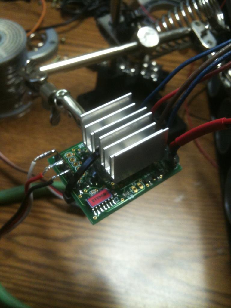
My new motor controller came in but the Radio Shack by me didn't have any heat sinks so I will have to try some other stores tomorrow. But with a nice long weekend I should be able to get him moving. I'll post some video when I do. I've also started working on the arms. First, I am epoxying some PVC in the arm holes of the torso.
And the only reason I'm farther than you are is mine is not nearly as complicated. You are doing so much with your bot it is truly amazing.
Thanks,
Bret
My other option is to pull the ESC out of my omnibot BOB (since I have already started using some of his parts) and just use that.
What do you guys and gals think?
I am not sure this will work for my needs on B9. I would like to use joystick control for movement.
After fiddling for a bit I did get B9 to mover better than with the first controller, but not as good as I think he should.
Thanks Josh, you are are truly a good guy.
Bret
Specifically: cgi.ebay.com/ws/eBayISAPI.dll?ViewItem&item=160755601853
I only ran mine for like 10min so far, as I just temp wired it to test before starting in on building it a body. IIRC, I had set the PWM at somewhere around 70-75% to get a decent indoor speed (meaning not to fast) with just the 6.2lb battery on it, unfortunately I don't know what gear it was in.
Turning on these rubber tracks will always be much harder on the motors then going straight, mine (my RAD tracks & my complete unmodded RAD 2.0) makes a more struggling when turning as well.
Can't promise anything, but I'll try to get it wired up again & take a video this week.
18ga should be good, it's what I'm using.
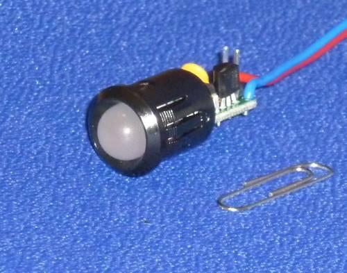
The 10mm LED indicator will signal at various levels - 3 colors, flashing, fast flashing. It can also be set as a charge monitor.
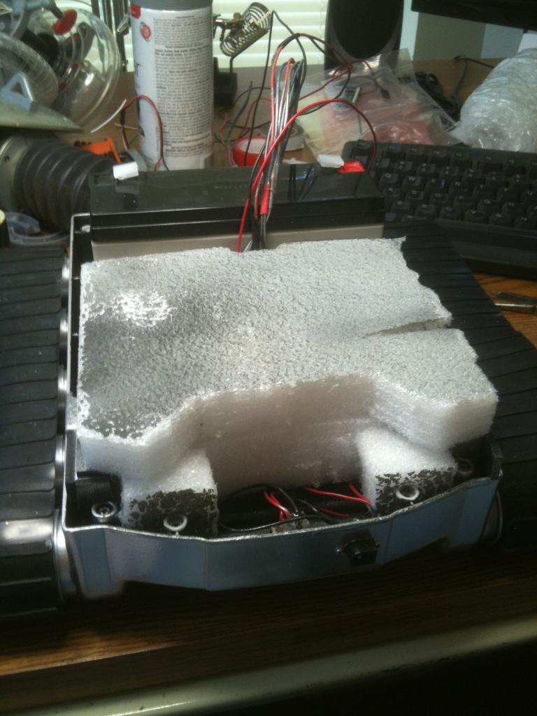
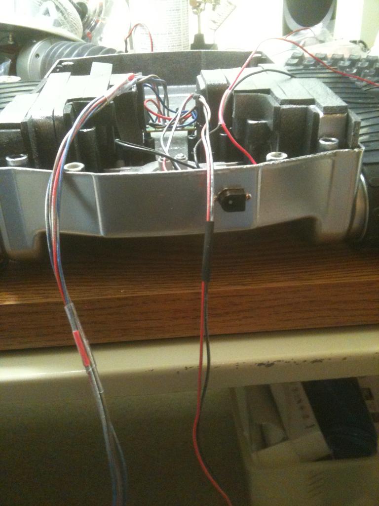
Then I have my foam core for a little extra sound deadening and support for the servo that changes gear. I also left room in the back to install my cooling fan (again, compliments of Josh).
Now to modify the cover to the drive section to accept the larger battery and the new cooling fan, then I can close it up and continue with the torso. Thanks to everyone for their suggestions and help getting B9 mobile.
Speaking of where is your project David?
Right now its just the tracks & a cedar framework for a 7" tall box on top, just tall enough to get a netbook above the battery & electronics.
I need to get the EZ-B & h-bridge mounted on it's 4"x12"x1/16" PVC sheet. The fuse block, euro terminal strips, & main relay are already mounted on an identical sheet. And get those 2 sheets mounted & everything wired/hooked up.
Then it needs the pvc box made that sits over the wooden framework, a 4ft tall pvc pipe mast attached to the back (where a Logitech Quickcam webcam on a pan/tilt will be mounted & an on/off switch near the top), bumper switches, & the ping sensor/radar servo mounted.
It's just a simple telepresence bot, which will be really useful for watching my CNC machine in the hot garage from my room.
Then I the modded cover for the fan you sent.
Then I put a good layer of the dynamat on the inside of the cover.
Hey Josh, on that fan it has a red, black, and yellow wire. How do I need to wire that up?
And this is the 12V power block with wiring to my motor controller, 6V step down regulators for the servos, and cooling fan for the drive section.
Plenty of room for other stuff (like powering EZB and lights)
I want to.help with.the port issue , can you please number the ports and list what is connected to those ports . Some things may be consolidated or a y connector for servos.
Total of 19 DO - this leaves one port for the "mouth" lights if I need it, or any other thing I may need.
@Josh - yeah, I figured on an amp for the sound. If you look at the leg section just below my power block there is actually a speaker mount. It is in the back so I may not use it. I may actually drill holes in a grid pattern (like you did for ventilation) below the lights in the "mouth" and put the speaker there. Haven't really decided yet. Any thought?
And here is a sneak peak of what B9 is going to look like.
Next I joined the pieces with standoffs.
Insert this assembly into the socket.
Then the outer cap completes the rotational socket.
The slot is for the arm base.
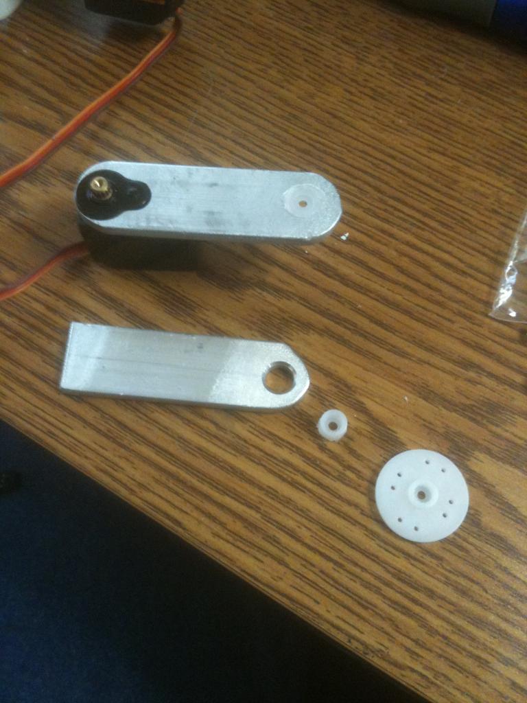
3/4 X 1/8 aluminum bar stock.
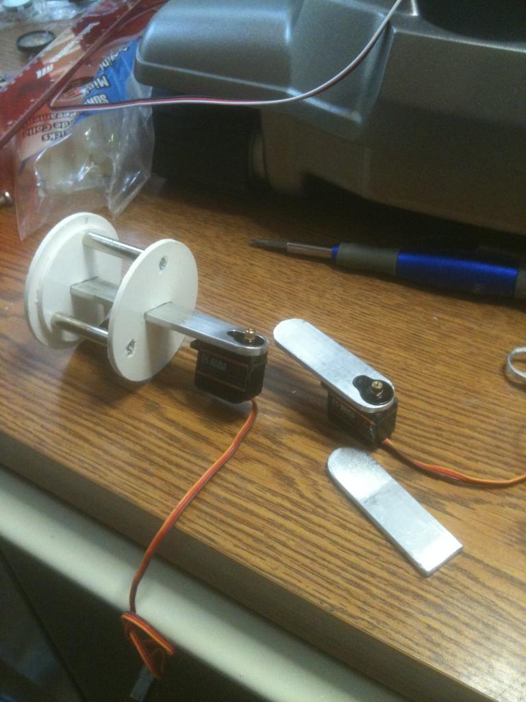
And the whole arm rotates with a servo on the inside.
In the video I am actually turning this via the aluminum bar and not with a servo as it is not secure in the arm socket. This is just for demo. Gonna work on it more today and update as I progress.
Then cut my arm pieces.
A step down bit and a file make mounting the servos easy.
Now to joint the arm sections and create my claws - oh boy!
If this doesn't hold up then I will look at using epoxy for mounting the piece in the hole.
Now to make a second arm and finish the bondo on the arm sockets. Getting close now!
And here is a video of the arm in the socket. It moves pretty well...
also just omnibot at a very good price thrift store near my house $20 and rad 4.0 at even a better price $10 from ebay,plus perfect shape in box rad 2.0 with remote not using him for EZB for my large collection of robots but other will use EZB
but specs says only 8 lb carry,it is a fair good chassis DAGU ROVER 5 CHASSIS
can you post a video of it carrying 40 lbs
BRET how much does the B9 robot weigh
thats why i wanted to see a video ,the company who makes it say under 10 lbs
so i wanted to see a video before i buy it
on ebay RAD'S going for under $30,i got one at $10 and another at $15 ,and third one restoring it
on my omnibot project i need super stong tracks like vex robotics ,because loooking at making it a BIONIC OMNIBOT
one very good reason to use better tracks,last much longer not much stress,plus less current too
Altogether - B9 is 17 lbs. And that RAD base with 12V battery moves him around great!
btw ...ok to use Rex instead of rgordon
thinking others will give you other ideas,so might need to try each one
Been working on my arms and hope to have them mounted this weekend.
witch i think it should
mine mostly take alot more time,beacuse i fully test everything,motors ,sensor and correct placement ,current load handling,drop test,plus current saving devices
drop tests very important,you dont want your robot to fall and repair the plastics latter
any robot can fall even if balance correctly
look at people we fall if hit a stone or a ditch
simple test just let it fall down,i do all theses test because i hate REWORK and CHANGES
You made the Rad drive fit B9 with style.
Glad you went with the 12v battery.
Under power never helps anything.
I look forward to seeing him altogether moving his arms and yelling danger.
I have a 3d computer model of B9 if you have any need of one.
No charge, as I didn't make it myself anyway.
I do make computer models and real robots.
Making progress with mine EZ-B but want to get the head built before taking pictures or making a video.
Sure, I need some pics of your robot.
@robotmaker - yeah, in the torso if you remove the device that pops his arms out. THere is also some room in the leg section.
It would be cool to a computer image of B9 - that would be great? Can you email it to me?
my girlfriend did a nice job getting all the boxes from ups and usps
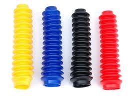
I got them in black, they are extremely flexible, the perfect size for me, and only cost $5.00 ea.
Now on to the b9 claw - this is a little more difficult.
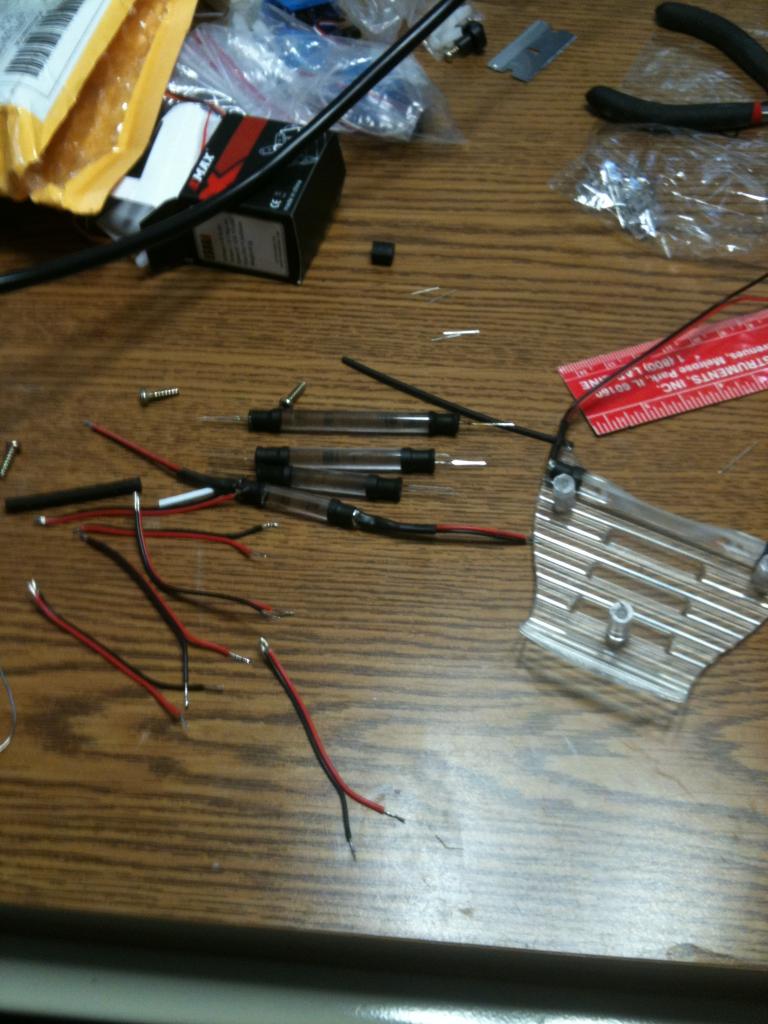
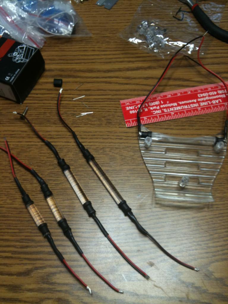
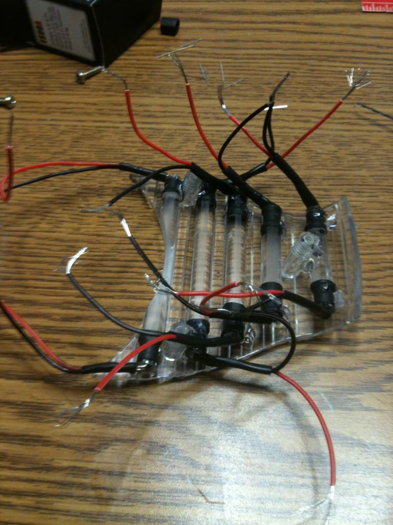
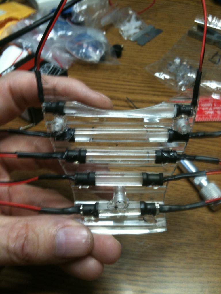
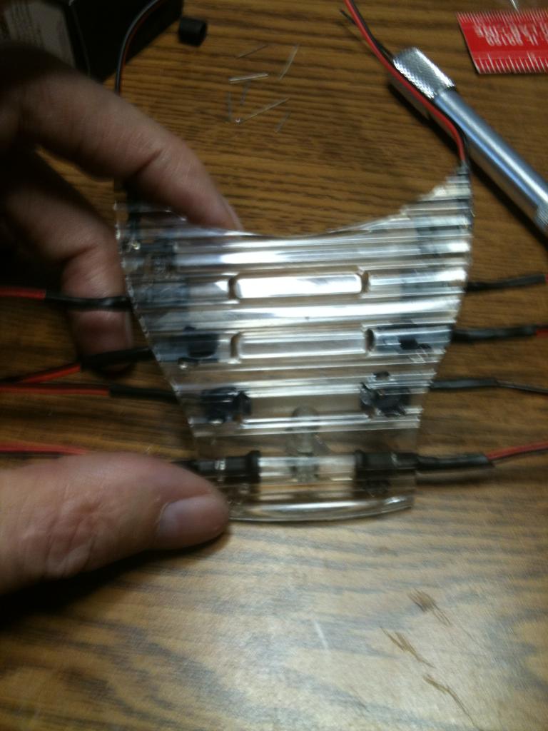
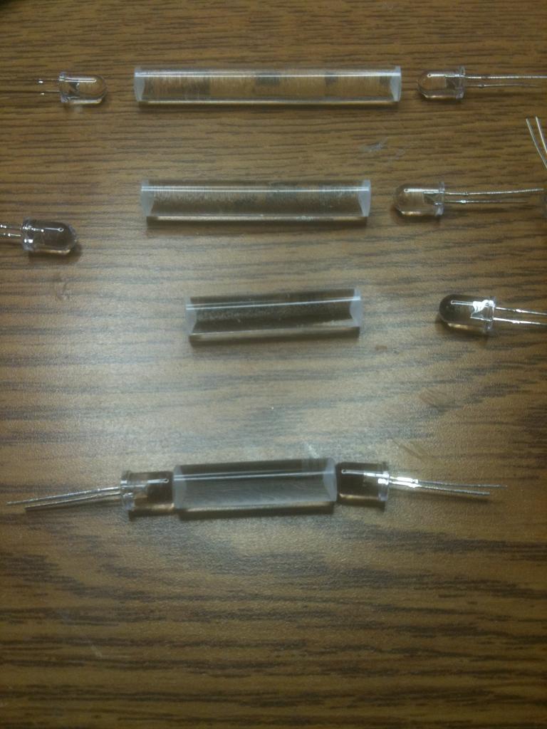
But I have also found a solution for the lights in the voice box of the robot. By using acrylic tubing and hazing the inside with a chemical, then putting an LED at each end, it lights up like neon.
also are you cutting it to use the bigger part of the shock boot too
i need a 3 to 4 inch one for my omnibot 2000 neck
they look great for hands and maybe shoulders ?
first my omnibot project ,its looking to be much better the JOSH javis ,even his is good robot
but that is where you start with one idea and make it better,and may nbe some day others might make mine better
with your it gave a few ideas to use and some ideas to make better
keep up the very good work BRET
@robotmaker it should be better than Jarvis for 6 million dollars ...
i cant wait to see the paint job too,your omnibot might have to much stuff ,BUT still looks good,good name for it OMNIVAC
delrin might be ok .,but the best idea and for paint to stick to is can use any good plastic and thin layers and add aluminium in between is like a sandwitch,and if done right the aluminium wont show
i did this before on a project,but dont rember what project it was
this way you get really good strength and plastic like the claw
plexiglass and acrylic is very brittle,why some like to use it i dont know,its great as windows for sensors or face plates,but impact level very low
another good idea about using aluminium ,besides low weight is that you can attached servo or pushrods or other stuff without it breaking or comming loose
ma kes it super easy to remove servo's then a gear goes bad or the servo
@GLICKCLICK nice site for bellows
rubber bellows
right now not at the point to buy any yet,hopping to finish my omnibot frame and post photos and parts of all parts used,i see most dont post a complete parts lists for each section of the robot
makes it super easy to build any robot design anyone makes if a part list is made
BRET on ABS if you use instead of the aluminium design,www.mcmaster.com has very cheap prices on ABS sheets many sizes and types
i get my parts in 2 or 3 days very fast shipping
delrin not a good choice unless you sandwitch it between other plastics and very slippery and paint hard to stick,same with nylon,mostly great for gears and fixtures
What is the ID of the bellows you need? I can look around here and see what I have.
whats super great about using resin molds compare to fiberglass,first no sanding is needed,very flat surface,sometime stronger,a lot cheaper,plus not very messy and easy to shape in a mold
i know JOSH loves using fiberglass a lot ,BUT ITS NOT GREAT FOR ROBOTICS,unless you are will small holes using only BONDO
Can't wait to see these crazy arms moving around , really khudos to you! I think you did the best b9 arms ever. Even comparing them to the life size replicas I believe these will move more like a robot and less like s guy in a suite.
silicone is easy to use,and molds not hard to make too
what i use a lot in making molds is moulding clay,sometimes you need a release compound to remove your cast from the mold,also parchment paper works great or vaseline
and Thanks Josh! I am pretty pleased with those arms.
I just won a bid for a 24 inch B9 off of ebay and will be modding him as soon as my humanoid robot is finished.
Also my B9 is missing the front leg panel. How much would you charge for a copy of the leg panel?
Looks like a fun project. I have always love this robot.
I can't wait to see your progress with your B9.
I will need to paint it anyway.
Let me know how much you want for it.
I just got some resin, but I haven't ever made copies of parts yet.
Thanks Bret for finding me help so fast.
but looking to start doing some casting of my omnibot project,and moulding clay i can use over and over for many casting projects,MOSTLY WILL BE ABOUT THE COST OF THE RESIN
not shore how much i have ,may need to buy more
I would love to see his arms together and working.
They finally shipped my B9 today. So I hope to have it soon.
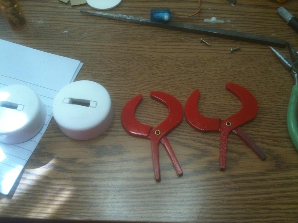
Next to this one is the original arm and claw off the B9 toy.
Then I modified a couple of drain pipe fittings to use as the cuffs on the end of the arm.
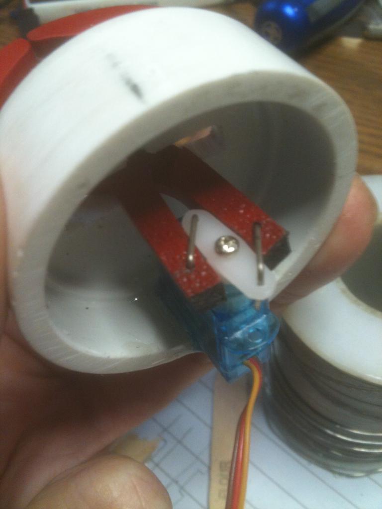
Next I cut my claws out of ABS and made a notch in each half with a forstner bit.
and here is the claw before paint.
Next I will finish the cuffs and install the claw mechanism on that. Then mount that onto the end of my arms.
alot will be using very light weight aluminium for many reason ,biggest it easy to attach arm motors ,circuit boards and more,plus a lot stronger then fiberglass or plastic,still will have the outer body of omnibot
sam looking to do the same on the B9 ROBOT even the claws,except for covering will be plastic
I almost got my B9 today, but I was at work when Fed Ex came to my door.
I will get him tomorrow for sure. Then I will need to get some rubber boots for his arms. lol
I have lots of vacuum cleaner hoses. They might be a bit too stiff. I will see better the size tomorrow. Anyone ever try the waist motor in a RAD for tilting a B9 forward and back?
Might not handle the weight. If I make rubber legs for B9 he could do his power unplugged bend forward with arms dangling. Would be cool if it worked. I know RAD can pick up a basketball.
Not many toy robots can do that.
i bought 4 of them,one to restore,1 for (going to be RAD project)1 for B9 robot i think
and one left over for parts ,so may have 2 waists not using
i like a very heavy duty base,one main reason i may go with vex robotic tracks
looking to make mine super close to the real B9 robot
and i think JOSH meens ROVIO ROBOT BASE witch is very high cost robot to use only the base
i have one i can control using my mind with EEG headset
That sounds cool.
I got my B9 today!
cant make movies no more sold all my high end video equipment
dont need it and video doesnt have much use any more
also looking at getting another type of headset for $200 ,this one can get software to can control some robots and arduino board
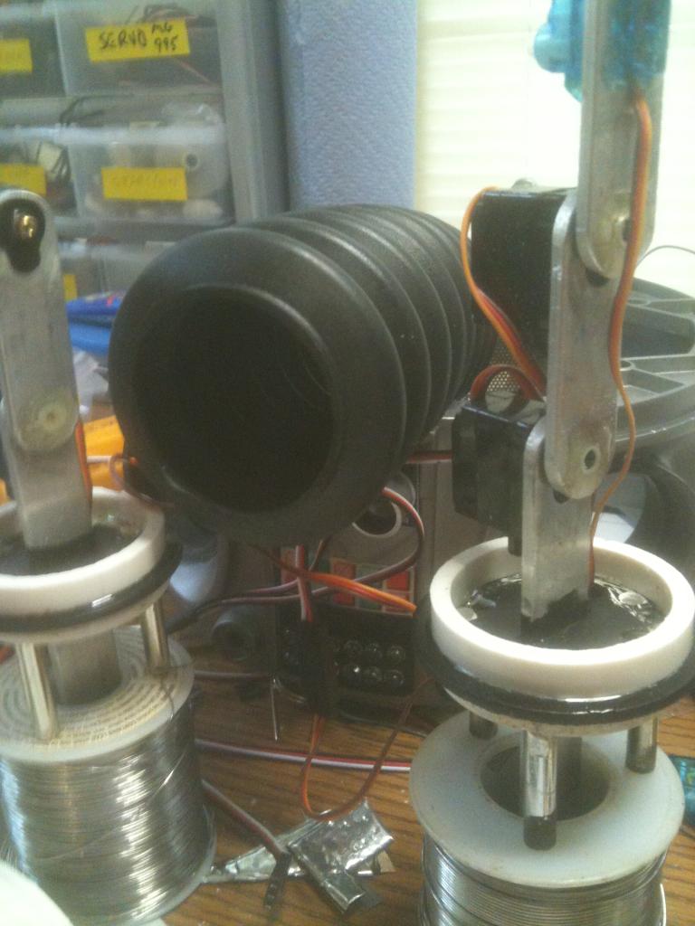
THen I mounted the arm in the socket.
And here is the boot on the arm - not too bad.
I am in the process of painting the claws so it will be a little bit before I get those mounted. In the mean time I will continue with the other arm...
Will look great with your new claws.
Hope to see the pics soon.
Got to get my humanoid done first.
Anyone have the remote that came with the 24 inch tall B9?
I was just wondering what all he could do?
I need to finish my humanoid project first.
Thanks
I will be glad to pay more than cost to you.
Thanks
And the cuff fits perfectly on the end of the rubber boot.
Here you get an idea of the size. Pretty darn good I think.
I am going to mount the servo that controls the claw to the inside of the cuff so it is a whole unit that can be added onto the end of the arm.
He will look so cool with his arms and claws in place and working.
For his sonar you can scan side to side turning the upper body.
Looking super good on everything.
This B9 can go where most will never go and move his arms better than most full scale B9 robots.
In place between the claws arms
I will mount the servo horn between the arms to open and close the claws.
But first, some paint!
Makes me want to work on my B9.
Love the lights, arms , claws, body turning, head turning and those RAD tracks.
All comes together with a EZ-B, sonar a video camera and you have the best 24 inch modded B9 robot ever seen.
One RAD B9!
THanks!
(sorry, I just had to say)
The servo works great!
Now I'll paint this claw and while it is drying I'll work on the other one. I didn't do them all at the same time as I wanted to make sure I had it all worked out before investing the time in two of them.
i have a lynxmotion johnny five looking to add at sometime a EZB,still waiting on a quote from DJ for many EZB's i got many many robots that need EZB
hand part looking to use,but claw looking to make mine a little stronger
tracks system looks good,but looking to use different tracks more like the real B9 without much changes,that and a computer board to add
B9 is one of my all time favorite robots.
I am sure everyone wants to see the whole robot.
Then we want videos!
can buy 1 to 10 or 50 still price the same
for a larger robot not great for ,but still will work
like the new board running at 70 mhz uses arduino software and few others
i have 4 and 5 on order and still need may be 5 more,have many toy robots ,only using one per robot
Now all ya need is the arm flailing about action (DANGER DANGER WILL ROBINSON)
you have set a standard to work for.
His claw opens plenty far too.
Looks like he is ready for his EZ-B and the new servo AutoPosition script.
Hope to see him all together and yelling danger as he waves his arms and drives around not crashing because he has sonar.
I need to download some B9 sound clips. Nothing adds more life to an animated robot than good sound.
Great job on everything you have done with your B9.
B9's got a mean chop there , I hope he dont run amok , that would be worrying .
Getting better all the time , Nicely done.
Steve_C.
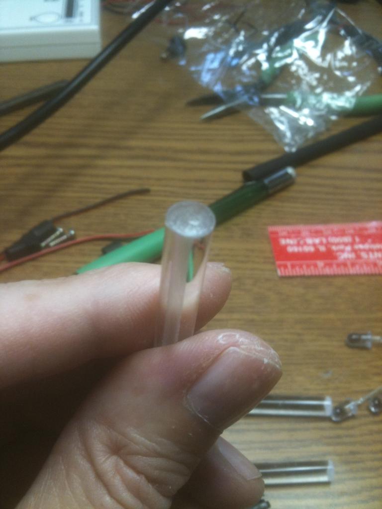
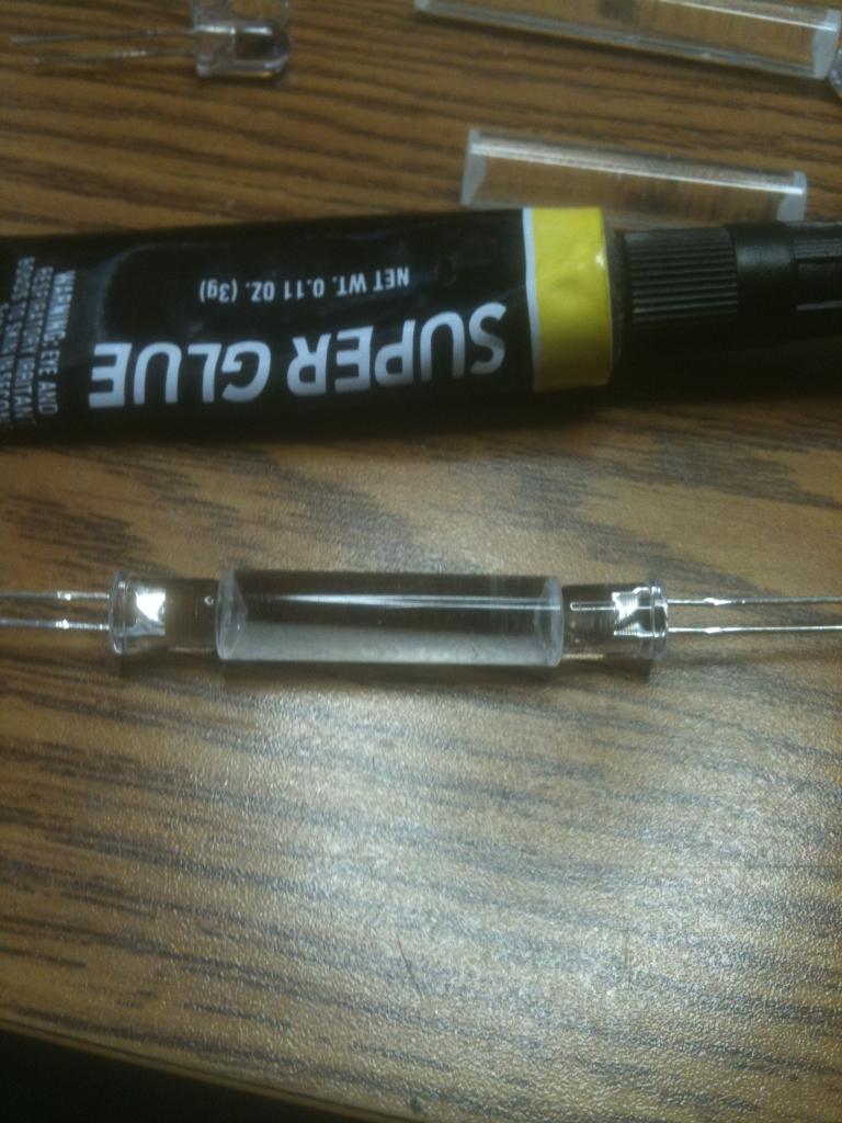
For the lights I am using clear/red LEDs and solid plexiglass rod. I cut the pieces to length and made a divot in each end with a drill bit. Then I filed a flat spot on one side - this helps to make the rod glow when seen from the other side.
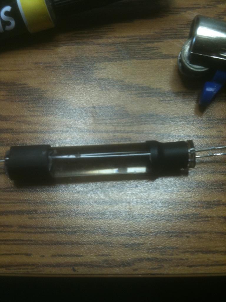
Then I super glued the head of the LED into the divot of the rod.
A little heat shrink tubing and I have a light bulb.
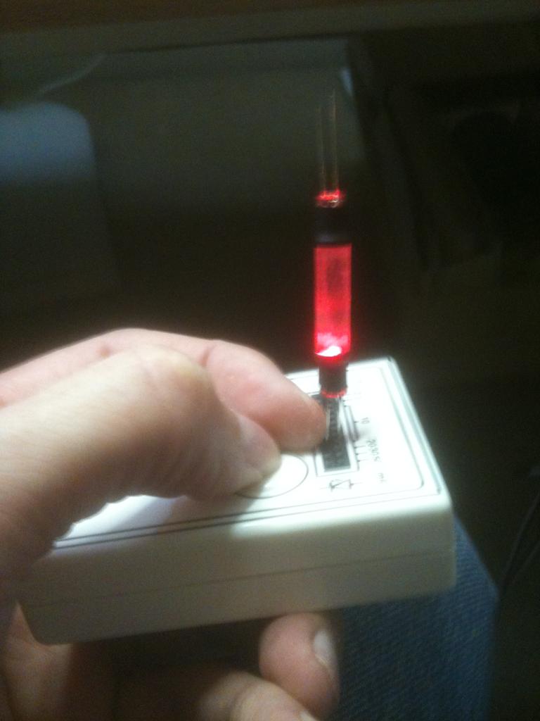
Then I put one LED in my tester and got my light. Note this is only one of the LEDs lit up. With both it should be fairly bright.
Now you need a Dr Smith or Robbie the Robot to go with him.
Anyone see any 2 foot tall Robbies anywhere?
If they have any they wont be cheap. lol
I always wanted a little cylon robot wondering around the house.
to see winter the dolphin,plus zoo's and busch gardens and more
but after see about sending some of the flex tubbing
And this is the controller - too cool!
Color LCD so you see what he sees. Obstacle avoidance, working arms and hands. So much to mention. He may be too cool to mod. Yeah, way too cool to mod (for now, and if DJ makes this a platform for the EZ-B so we can write new code mua ha ha ha)
Check out this link for some further info I found:
www.robinhewitt.com/roboscout/index.html
I completely understand your reluctance to gut this cool, big, and slightly rare robot. Kind of like my feeling toward my Ultimate Wall-E. However, if Roboscout ever breaks down or if it can be integrated into ARC similar to the AR Drone, as Gunner stated, then all the better.
Can't wait to see more of Roboscout. Enjoy your new robot friend!
Okay, after this it's back to B9 - I wouldn't want him to get jealous. haha
He and B9 can be friends.
This program is free and works great.
I use it on all of my computers.
And I am using Audacity - it is great.
B9 will always be one of my fav robots of all time.
No other TV robot comes close.
B9 had some of the best lines in Lost in Space.
Your B9 will have many of those great lines.
I am sure kids of all ages will run over to see him if you take him anywhere.
hope to see your design finish soon,when i get back first finish omnibot project then start on B9
BRET your design going to look very cool
Bret, I remember when I was young. I used to go on a three week vacation to Disney World and all the places in Florida. I couldn't wait to get back to work so I could get some rest. Ha!ha!
Put together,
Mounted to back of the chest piece
From the front
mounted in place in the bot.
and finally a video of how it looks. Not perfect, but it will work for me.
ON a side note, this is what I had to do to get the battery out of my roboscout.....
The lights you made look great. Don't over critique yourself
You did a GREAT Job on him.
Hope to see B9 all together and having fun soon.
Roboscout
I think the next one (the kit will be for) is going to be the robosapien/tank combo.
Then the amplifier - very cheap and allows to me to adjust volume for my application.
All tied together with a cool speaker I got from Josh.
It all works perfect. My camera phone does not do the sound justice, at half volume it is really loud.
linky
http://shop.cointaker.com/category.sc?categoryId=184
Here's a link to a video one of my friends made about this ghosting problem on a pinball machine. Seems they found a way to fix this problem through the software ROM in the game. Don't know if the fix will help you here but the visual is great and nicely shows this problem:
http://vimeo.com/12823973
Good luck and have fun!
Dave Schulpius
Once we get AI running in these guys they will be like friends and not just robotic toys.
Who knows how smart they can become.
Good programming can make them so much more alive now that the robots can hear and see.
Measure distance and even scan the room with sonar. A blind robot bumping into walls is all in the past. Yes, robots still bump sometimes, but so do we.
I so much want to see your robot running across the floor talking and waving his arms.
He need a tilt switch so he yells danger when he falls or comes close to falling.
Got my voltage reduction worked out for the servos. 6V for the left and 6V for the right.
This will power the servos for the arms/claws, as well as torso rotation, gear change, and some of the lights. For simple plug in (so I could pull the top off for repair) I took one of the ribbon cable connectors off an old mother board and tied my power into that. Now I can just plug servo cables right into it.
Are you going to use speech recognition with your little guy? It's awesome being able to have a conservation with my full sized B9! The only problem is using the MP3 Trigger the mic pics up what B9 is saying and more then often he will interrupt himself with another phrase. DJ said he will work on a fix for this issue.
Dave Schulpius
where did you find your voltage reducers? i was wanting something like this for my project to power servos and lights.
thanks
I think in Bret's case, the stronger amplifier just had a stronger "hum" or background noise when there was no sound... thus causing the LED to ghost. Perhaps putting in a larger resister inline with the LED would keep the lower voltage from actually powering the LED.
@bret.tallent I really like the detail you are putting into your robot... settle only for the best
Linky
Gunner you are correct. The cheaper amp I used on the MP3 trigger has a background hum that is the LEDs. Since I added the second amp with a clean input just for the voice lights I don't get that effect. And I can adjust the lights independently of the volume to my preference. It is such a simple way to get the lights to sync with your voice I think I will use this method from now on.
You are making a cool robot even cooler!
Can't wait to see him running around and talking to you.
He needs a gun ontop each fender lol.
So are you going to eliminate the cup holder for more room? Its not too difficult just some epoxy and masking tape. I did it so I could fit one of those 12 volt 7 ah batteries inside.
That is too cool.
How can he get you drinks if you lose the cup holder?
B9 brings all the drinks?
Yes, he needs guns!
I will build my B9 when I get a few other projects finished or at least closer to finished.
THen I got my speaker mounted (thanks Josh)
Finish the right arm/claw
Identify all my wiring and connectors
Mount the head/bubble onto the torso
Make and mount the bracket for the torso rotation
Mount the torso onto the base section
Plug in all my wiring
Trouble shoot everything
Start Playing!
It's starting to look like B9 again.....
I think the red sensor goes on the left.
Not that he wont work right with them reversed.
They had his head facing backward on the toy so I fixed mine to face forward, but I made sure to have the sensors in the right places.
Science has found a planet that is .9 times the size of Earth and has a sun 1.1 times the size of our sun in the area where the Robinson family was lost in space. Sadly the planet is too close to its sun. But there is hope a planet like Earth will be found.
Next I mounted my motor controller onto this bracket.
Okay, I guess I need to break down and go paint that claw...haha. Then I can start hooking up some wires. Yay!
Now he is really starting to look like B9...
The leg section really is a great place to house the EZ-B and MP3 Trigger and amps. All of my wires are labeled and pulled through into the Brains compartment. But I need some servo extension cables and the ones I have are all 20 inches long. I guess I will need to order some 6 inch ones. In the mean time I can finish up the right arm.
Then I will need to test out all of my connections and ports, fine tune servo movement, and start with some programming.
Then Gunslinger Bob and RoboRAD get worked on. Yay!
I hope to see pics and videos soon!
I just got a load of metal gear servos and some 1/4 scale servos for more robot fun.
I also ordered another EZ B.
Can never have too many servos!
making metal arms with omnibot arm covering
Speaking of pictures, here are my final pics of B9 for this thread. Got all my stuff plugged into the EZ-B.
Close the door and it looks good.
Now he is all buttoned up and ready for programming.
I took a video but don't know what happened to the sound. I turned him on and his chest lights come on, and the green light on the lower right is his battery charge level monitor. The one arm needs a little repair as I messed up one of the elbow servos (broke the servo horn mounting screw off in the servo.