
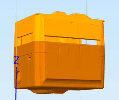
I did a mock up of the JD backpack based on suggestions from @WBS00001 and @ptp from my C3PO JD head post.
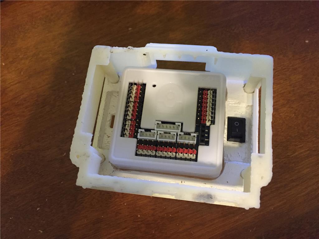
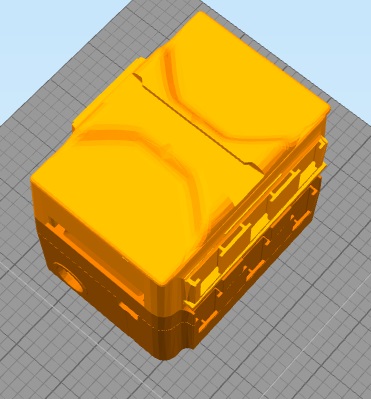
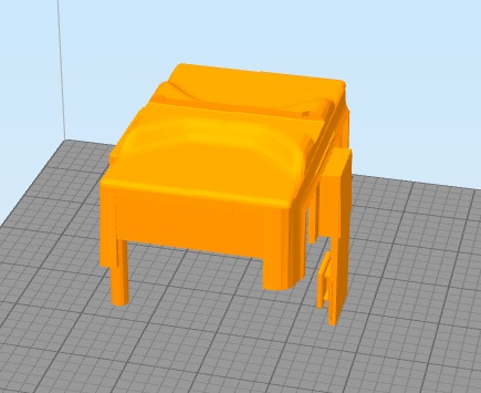
It has a male clip on the bottom to slide into the 3rd middle female slot inbetween JD's legs to anchor the backpack cover. It also has two posts that slide into the top two screw holes of JD to help steady the cover.
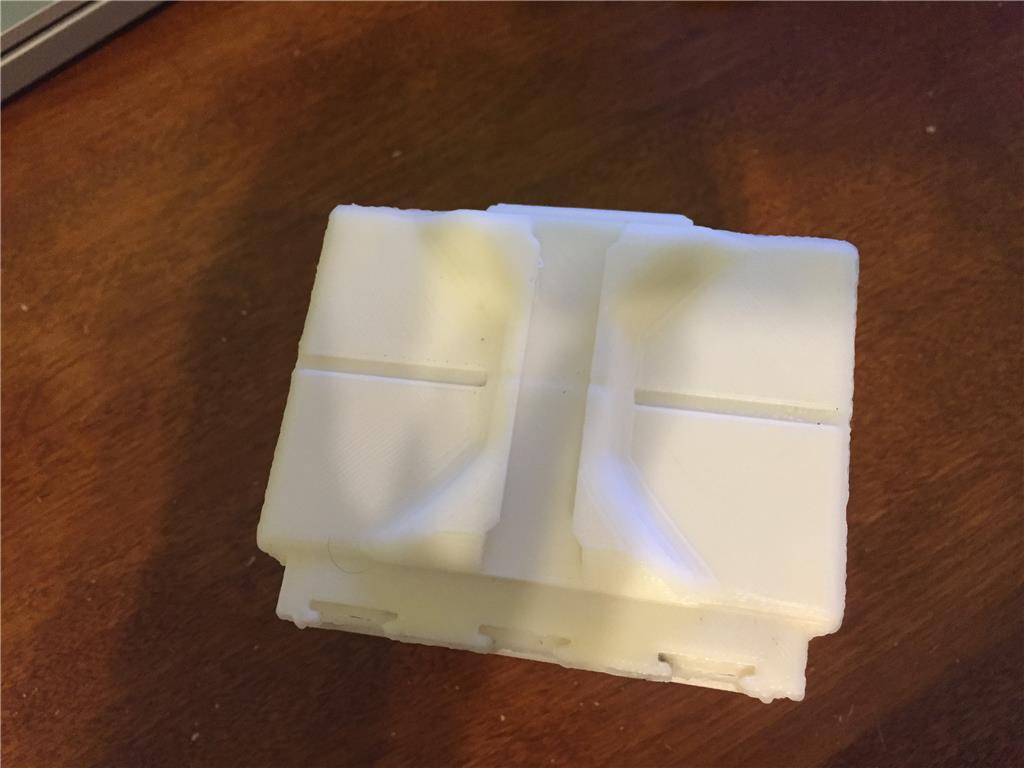
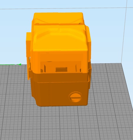
There is a dual female slot on the back where you can mount 2 things like sensor modules or light weight items.
I opted not to add a male clip at the top of JD as the other anchor point. I don't think it's needed for a cover, but I may make an alternative version and incorporate that idea. I feel like it would only be needed if you wanted to do something extreme like mount a 3rd foot or 2nd head.
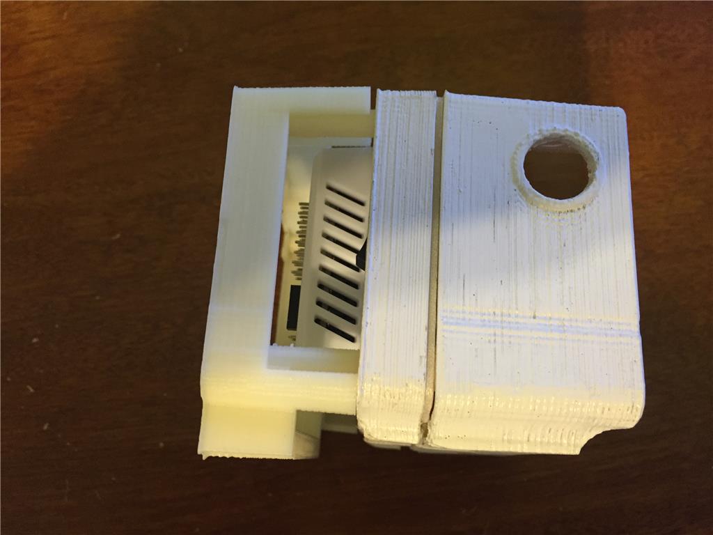
There are open slots on the top, bottom and sides for wires and the switch side has a big enough opening "most" fingers should be able to still access the switch.
I have not print tested it yet, I wanted to share the rough draft first for feedback.
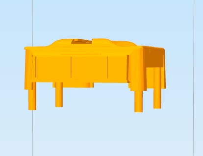
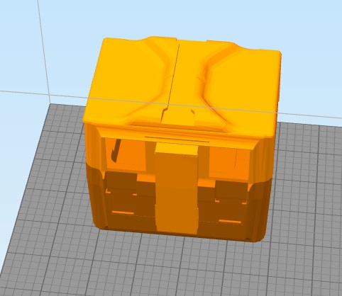
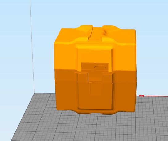
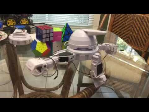
The backpack as it would appear on JD:
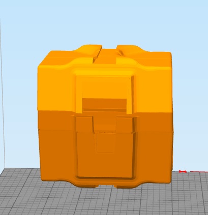
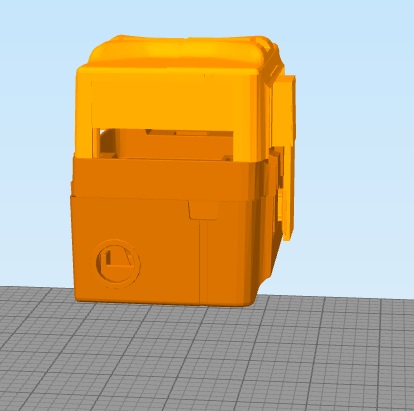
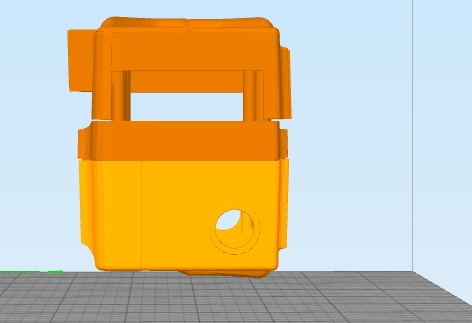
The backpack by itself.
I welcome suggestions and input. I think this is a community project.
Discover more robots
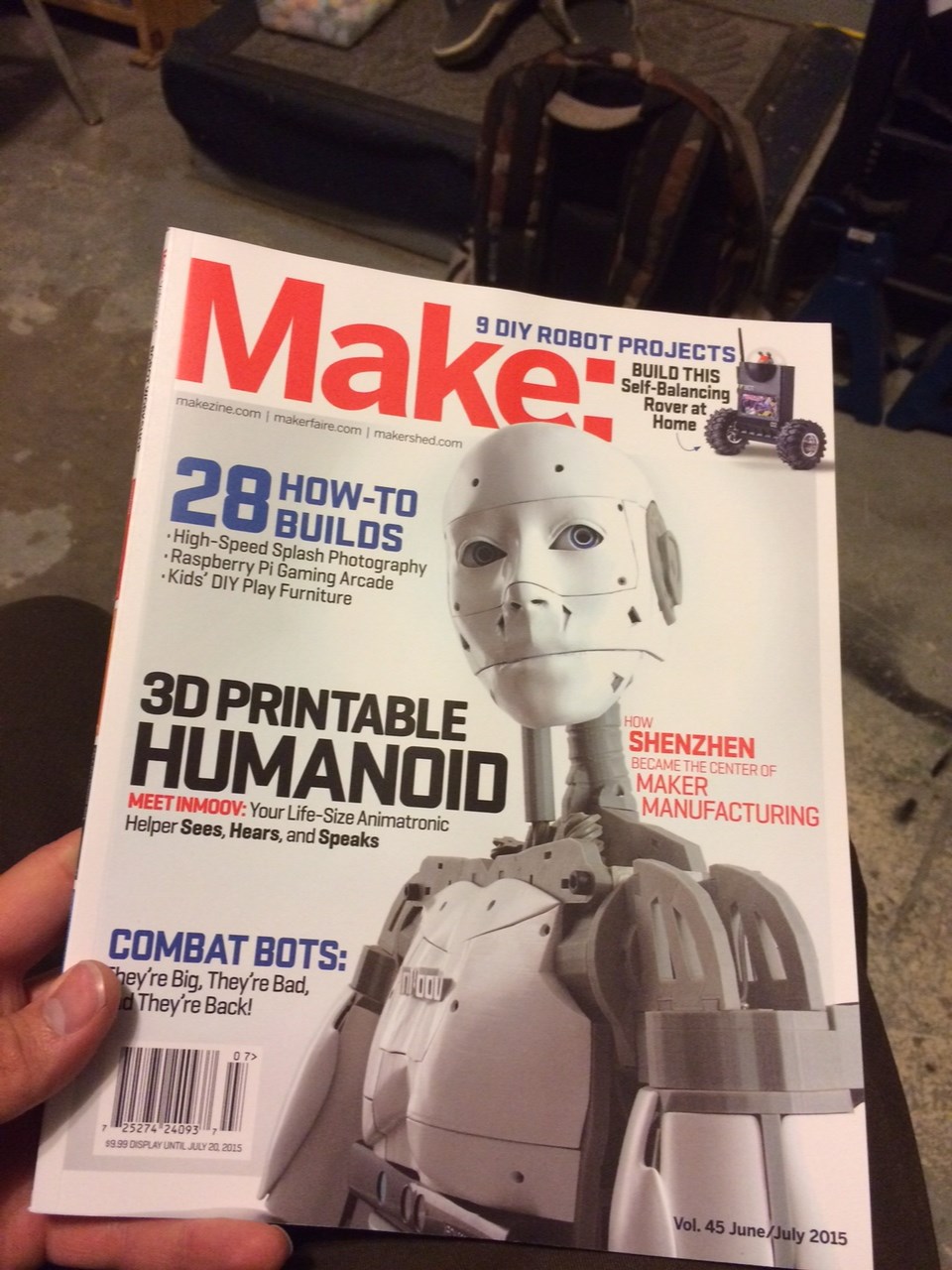
Jeremie's Richard R And Bhouston In Make Magazine
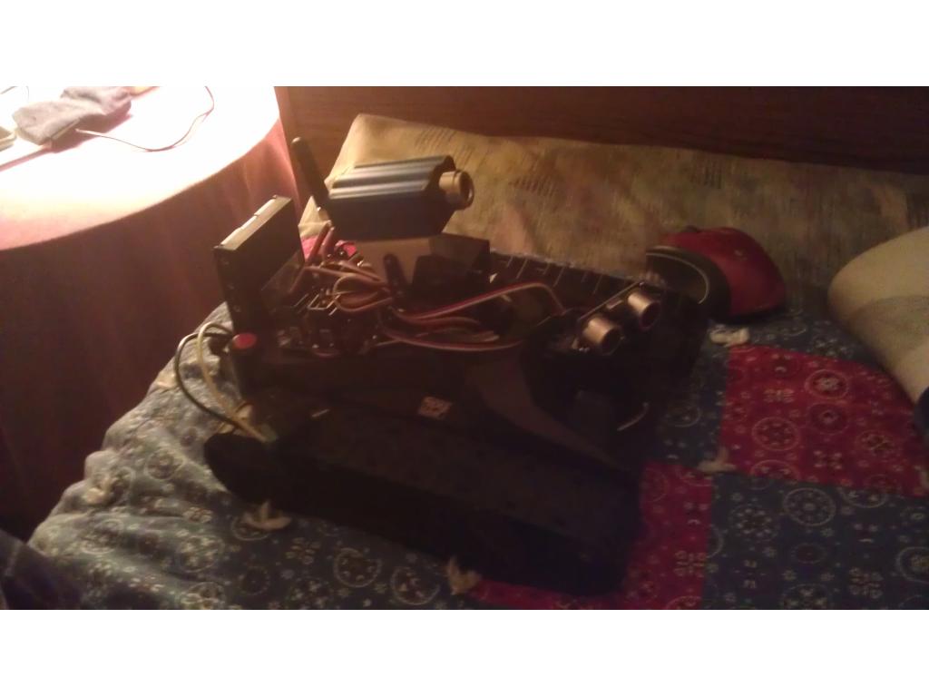
J's Rover My First Bot

looking great.do if you use the male clip on the bottom ,you cant use the , sensor for jd to get up when he falls.you can ad female on the bottom clip.
or you can also use 4 tiny screws and keep the original female slot. for the sensor.
i made a little video.you can use the tiny screws from the servo's dont drill a hole but use a heated tiny screw.this way it will be, as solid as can be.and stll have the female left for sensor.
Excellent work. Just excellent. Great idea of making posts to go into the existing holes rather than tabs on the top. I wonder if it would be possible to make them hollow such that a screw could pass through them from the back of the backpack? I was thinking that each would have a few mm of the tip part solid with a small hole going through it. The idea would be to be able to screw the unit in using the existing setup on JD but using somewhat longer screws. Just a thought. I have no idea how feasible that would be. It might require the post walls to be too thin. Nomad's idea about putting small screws into the sides to go into the posts sideways is a good alternative. That way the posts can be as thick as needed and it would be up to the user to decide if they want to go that route.
Also, I would echo Nomad's thoughts about adding a female clip to the tab which goes into the bottom slot on JD. Looking at JD I see there is not enough room (height) for it to go on the part that inserts into JD itself, so it would have to go on the portion of the tab which is attached to the backpack. Additionally, I would still like to see a female clip on either side of the bottom tab if possible. If nothing else, they would give the user an alternative place to insert the sensor (plus another one of some sort) if it is undesirable to make a female clip as part of the tab itself. And ... I'll admit it, because I really want to play with a 4-legged JD.
Thank you so much for doing this. It's something I have wanted to see for a long time. Next maybe we could discuss a 3-fingered claw?
hi the reason for not using a dril is because a 3d print is made out off, many layers.if you would dril a hole in it the layers become visible, and that weakens the body.by using a heated mini screw driver you make, the hole but also closed the layers by melting.
Thanks for the ideas @Nomad and @WBS00001!
Anthony original made or started working on a backpack for JD and he used the 4 post method, like Nomad suggested It's a pretty good way to go I think, it should use less plastic and will print cleaner than the male clip method.
You can design a part like this probably over a dozen ways, each with some pros and cons, but the middle of the road method I think is the 4 post method and to really anchor it, use side screws like Nomad suggested.
The center tap and longer screw method is not something I can pull off and I'm not sure how many folks would be able to find the right size screw even if I did. And I think it would risk damaging the original screw thread slots in JD with different screws. The print tolerance would be pretty tight for that method as well.
I did add 3 female slots to the bottom this time, which really cuts down on the slack for wires going in at the bottom. Along with the 2 on the back give 5 additional slots!
Additional suggestions, ideas or thoughts?
it looks great.you can use the screws that comes with the servo here in shop.
screws
justin this is a great contribution for the forum and all who has a jd robot.
maybe an opening on top for the wires rgb,servo,camera
thank you
Those screws would work for the side screws I think. There already is a slit in the top for the cables from the head.