-636348381130562972.jpg)
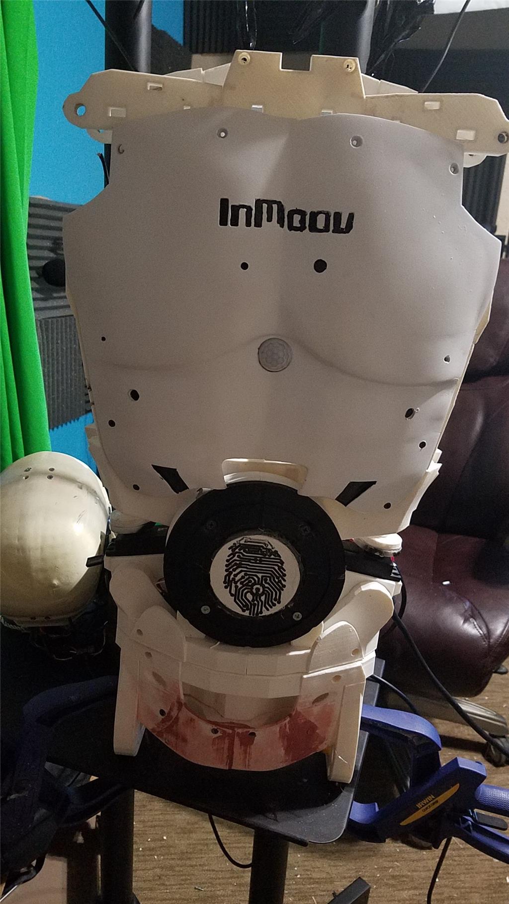
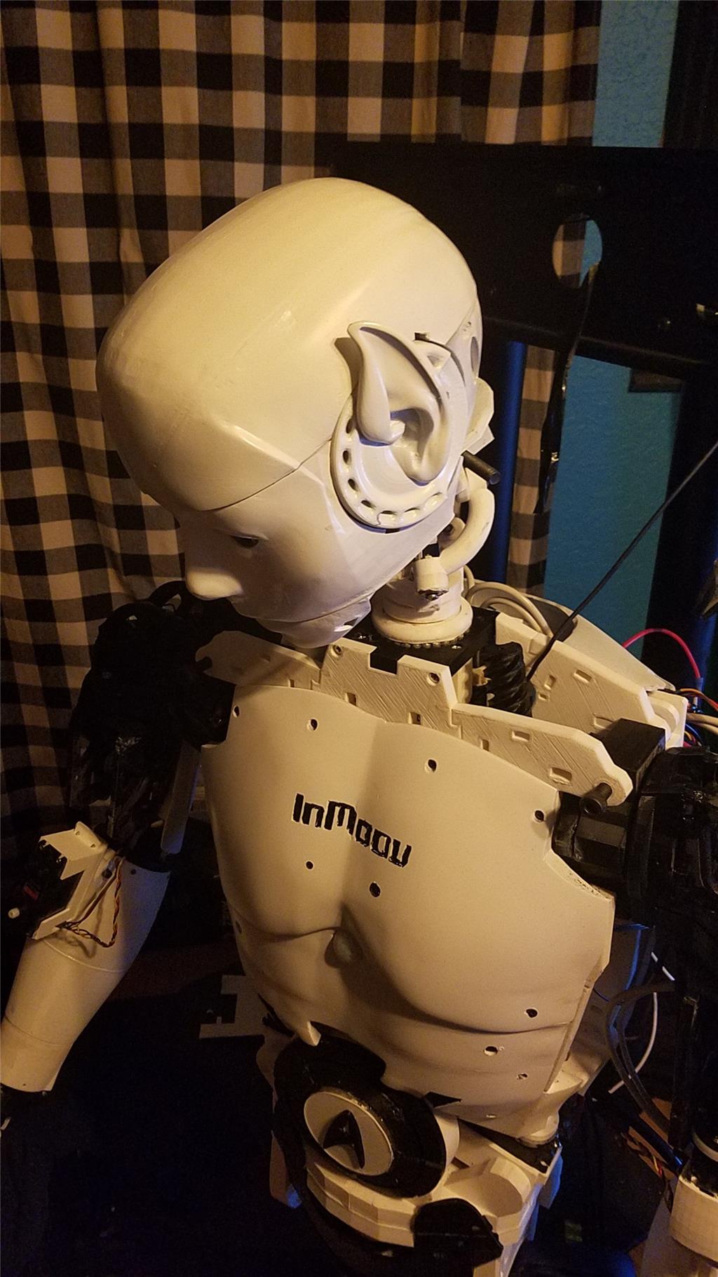
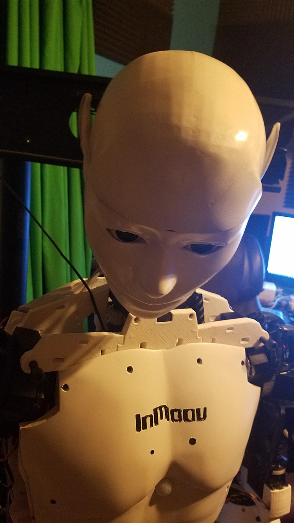


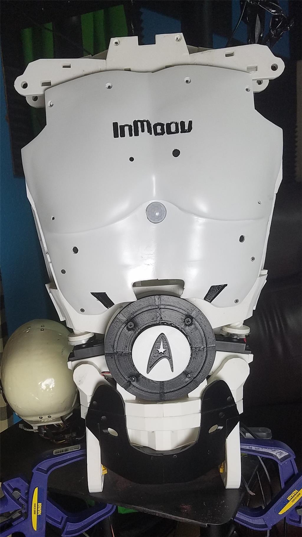


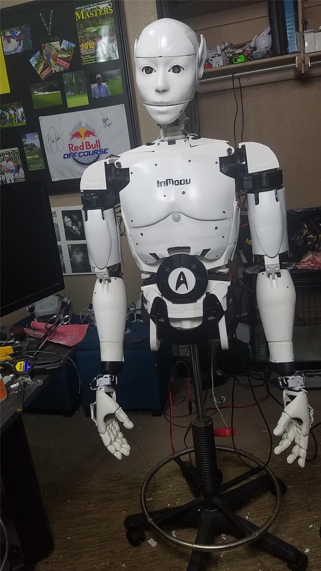
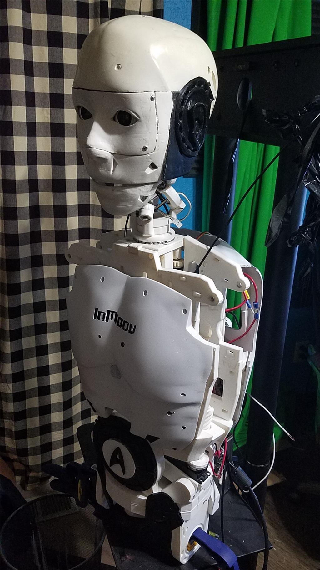
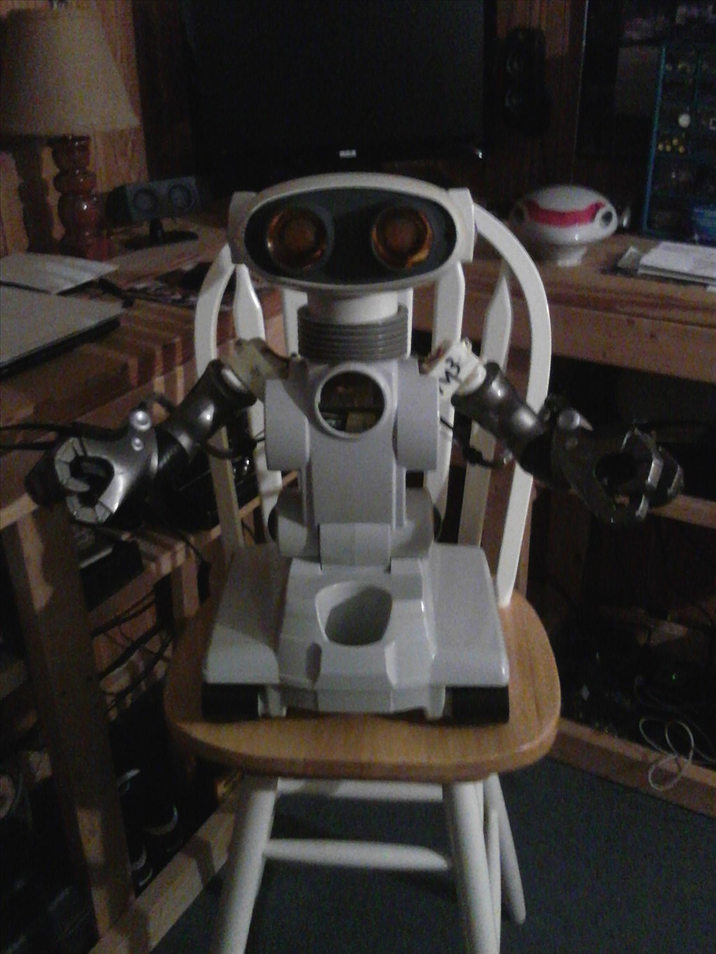
I have decided to start my InMoov project. I think I will call him Spock out of respect to Leonard Nimoy who passed away on the day that I started this project.
I am editing this post so as not to confuse people with the current configuration. I continue to update this post with the latest photos. If you are reading this for the first time, don't be confused. There have been a lot of changes to the InMoov over the past couple of years including starting over.
https://synthiam.com/Community/Questions/7398&page=21 Post 203 starts the rebuild of the InMoov.
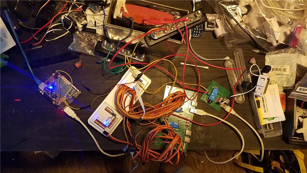
I have decided to use an onboard computer. I chose the Latte Panda due to it having an onboard arduino Leonardo and also because it uses little power.
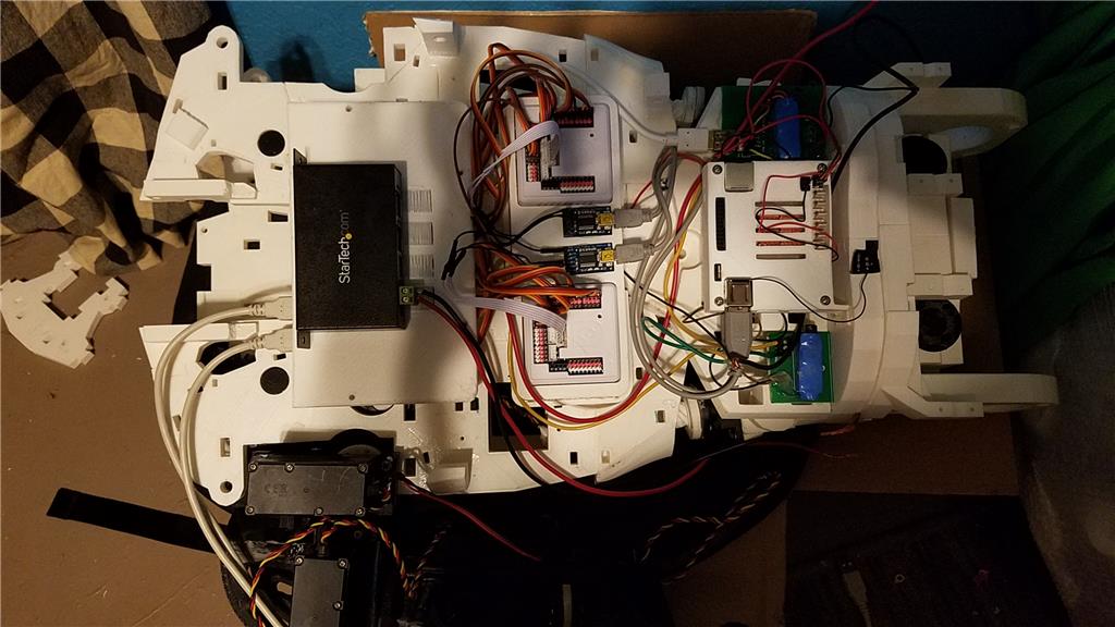
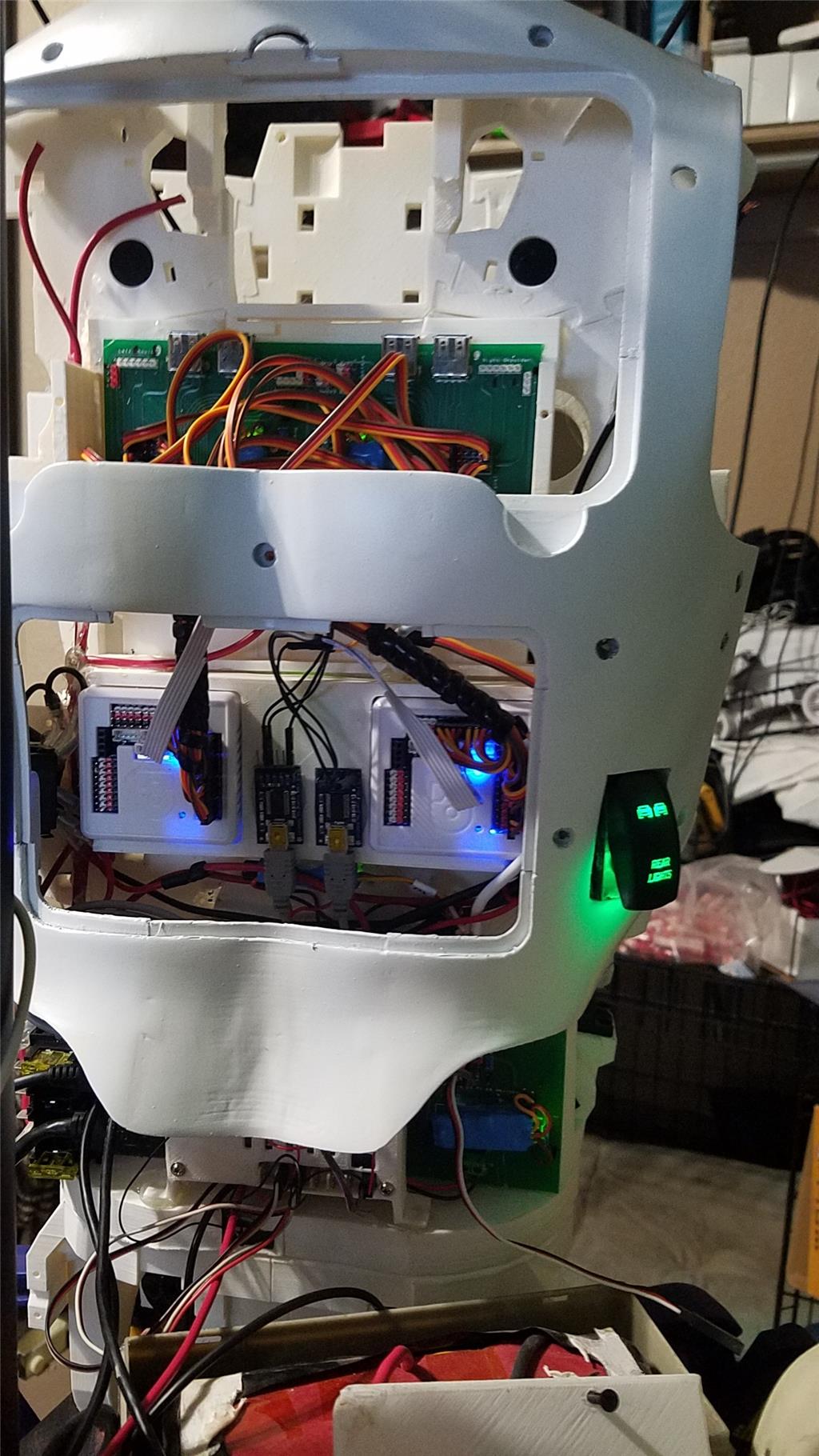
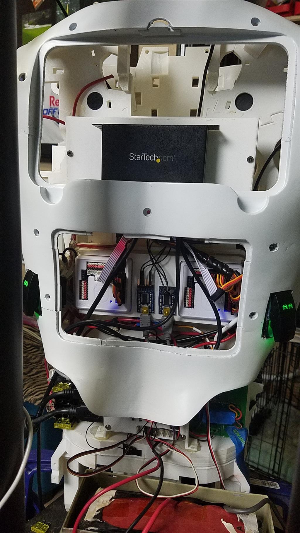
I used 2 EZ-B controllers connected via the camera port to Adafruit FTDI friend boards. This allows the Latte Panda to have a non-wifi dependent connection to the EZ-B's. I use a powered USB hub connected to the USB3 port on the Latte Panda to attach other items.
The Omron HVC-P is used to identify people, emotions, human bodies, hands, age and gender. It is attached to the Latte Panda via an FTDI friend which is then connected to the powered USB hub. It is mounted in the chest of the InMoov. I also use a 3 element microphone which is a MXL AC-404 microphone. It is disassembled and the board and microphone elements are mounted in the chest of the InMoov. This mic board is connected to the Latte Panda via a usb cable which is attached to the powered USB hub. There is a USB camera in the eye of the InMoov which is connected to the Latte Panda via the powered USB hub.
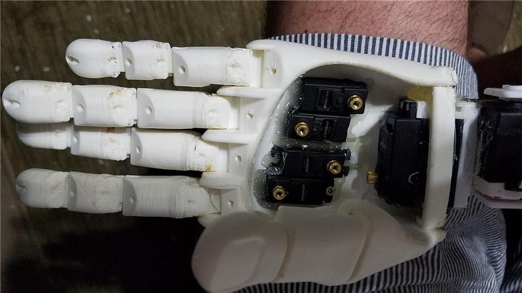
I chose to use the Flexy hand with the InMoov. The design is far more rugged than the original hand and works very well. There are 4 EZ-Robot Micro Servos in the palm of each hand which controls the main fingers. The thumb is controlled by an EZ-Robot HD servo. The wrist waves and uses an EZ-Robot HD servo to do this motion. I use the standard Rotational wrist.
I have castle BEC's for power in the following locations set to the following voltages. Forearm's - 6.2 V - Controls fingers, wrist and elbows Custom power distribution board (2) set to 6.2 V controlling head, neck and Shoulder servos. EZ-B's - set to 6.1 V - it is mounted in the controller mounting plate and connects to the EZ-B fused power boards from a power base. Latte Panda - Set to 5.1 V and is mounted to the EZ-B controller mounting plate. Waist - set to 6.2 V and is mounted in the lower right side of the back. This provides power to the lean and pivot waist motors..
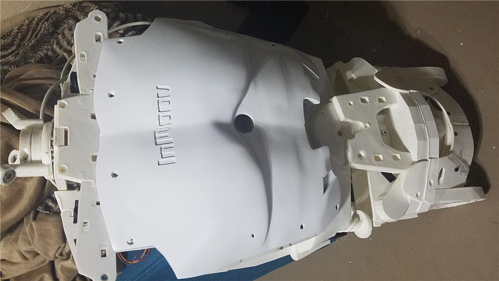
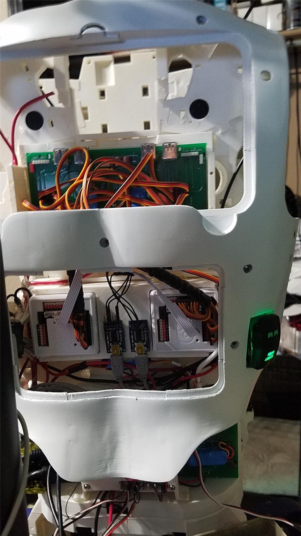
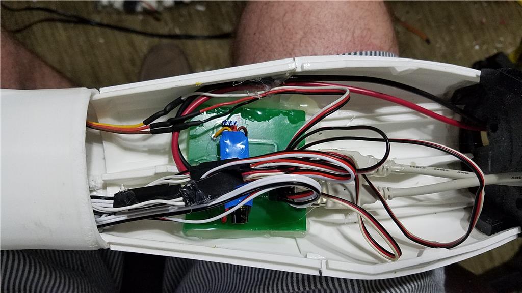
There are some custom power and signal distribution boards. These are in the forearms, lower back and in the upper back. The upper back or main board connects to these distribution points via USB cables to provide signal to the other boards for servos. The main board also has servo connector pins that are for the neck, head and shoulders. This allows the power to be distributed between multiple BEC's and also allows the servo signal cables to be shorter and more protected via the USB cables.
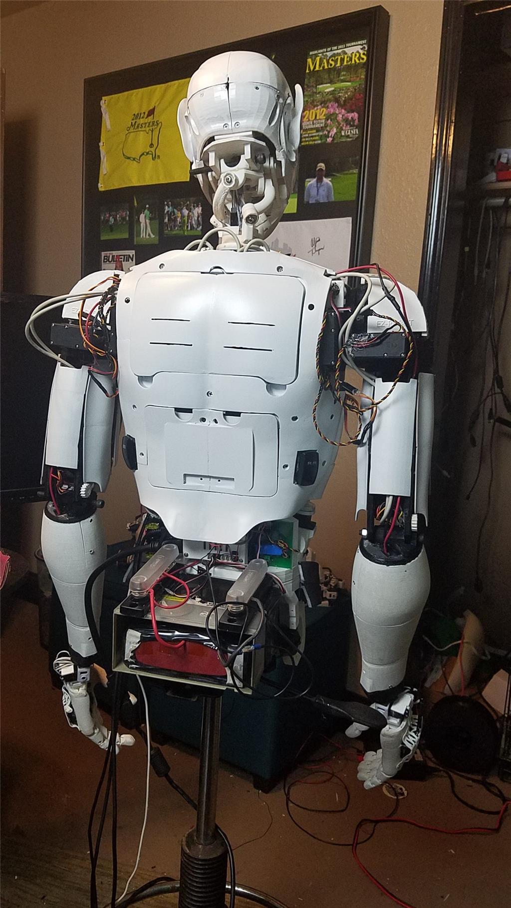
For power I use a LiFePo4 battery that is rated at 30 amps. It has the balanced charging circuit built into the battery and also has a low voltage shutoff built into the battery. This protects the battery and allows the battery to be charged with standard car chargers.
I put switches on the back on the InMoov which are rated at 20 amps at 12 volts. These are rocker switches that allow the user to pretty much slap the switch to turn it off. There are two of these switches. The servos for the elbows and fingers are on one switch. The latte panda, neck, shoulders, EZ-B's, waist motors and some lighting is on the other switch.
I also added a fuse block. This allows 20 amp fuses to be put in line to help protect things. The switches above drive the fuses for each of of the motors listed in that section.
-636348716348649435.jpg)

Discover more robots
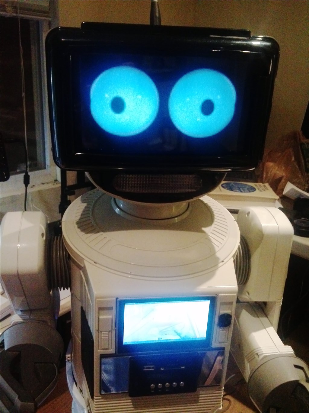
Donesvarc's Wall-E From Czech Republic
Rb550f's Super Omnibot

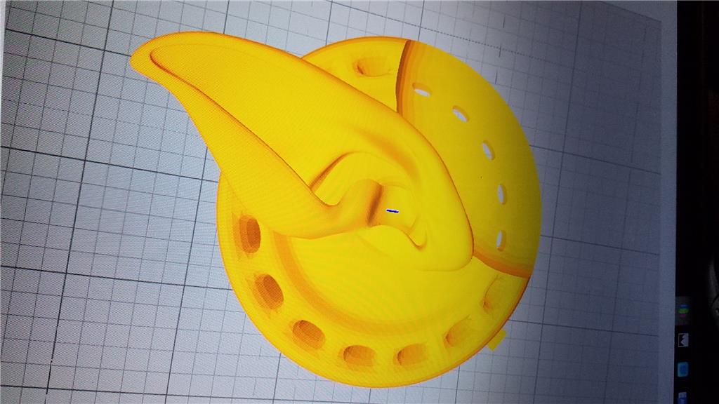
I had to end up printing each part of the fingers individually for the replacement hands. I only have left to print the NinjaFlex joints. I plan to do that this evening as I expect there to be some tinkering with the printer to get it to print well.
Attached is the current progress of the printing. I could have completed in 30 days, but I had other things come up that prevented me from being home to monitor the prints and had one printer down for about 3 days or so.
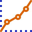
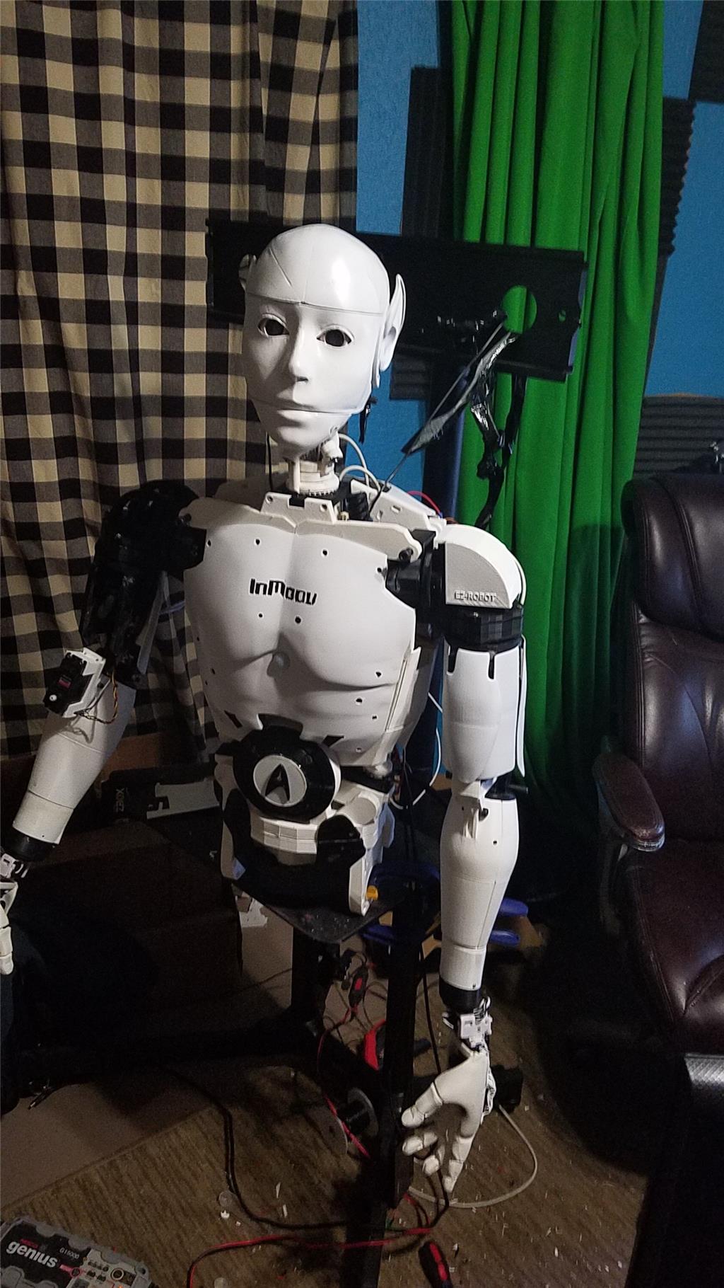
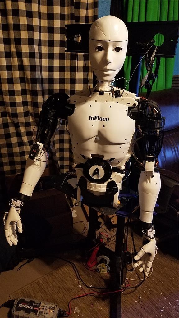
I have started building the shoulders and then will work my way down the arms. After it is built without any electronics and all of the pieces are put on and aligned, I will start the sanding, filling and painting process.
PrintStatusInmoov.pdf
**Edit - I forgot to add in the other filament used. Updated spreadsheet. The answer to the question for my reprint is that it takes about 60 days of pretty constant printing if you have a single Flashforge Creator Pro to print an InMoov. It costs around $180.00 in filament which is a little over 9 KG of filament. This is printing every part using supports and rafts and using some pretty high wall counts and tops and bottoms for parts that take the most abuse. The parts that needed to be strong I used a 60% infill while the cosmetic pieces I used a 30% infill.
I can say that NinjaTek Cheetah prints very well and very easy. It isnt as flexible as NinjaFlex though so I may be reprinting my hand joints for the alternate hand with NinjaFlex if these are too ridgid. Anyway, printing is complete.
Dave, just play with your settings if the hinges aren't flexible enough rather than buying more flexible filament. I printed the finger hinges with 2 shells and 40 % in fill and they work good.
Gotcha, Thanks Bob!
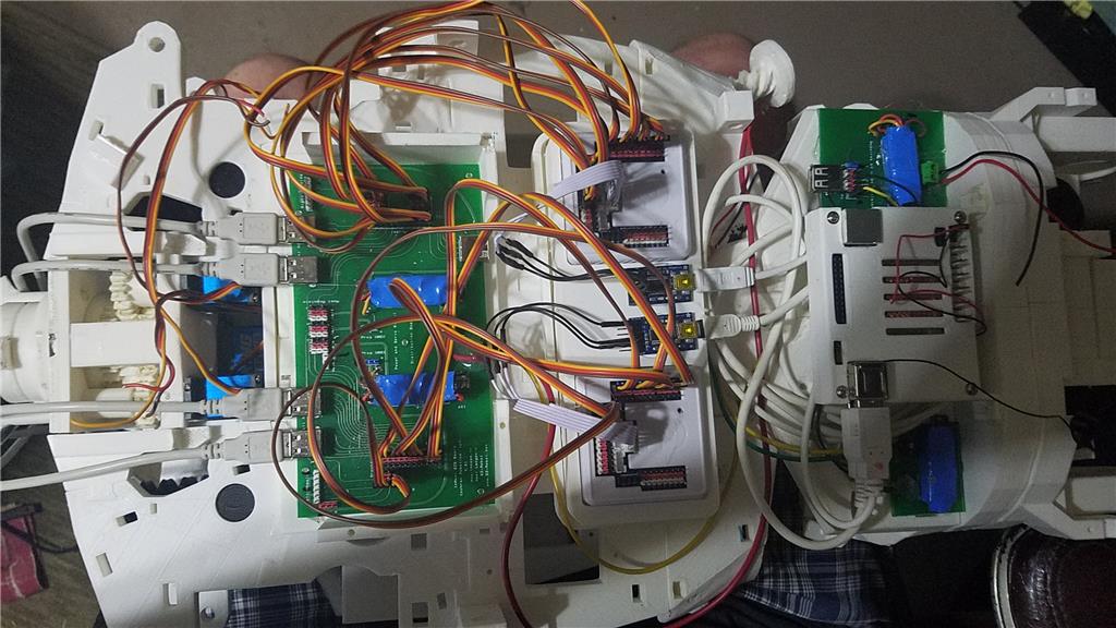
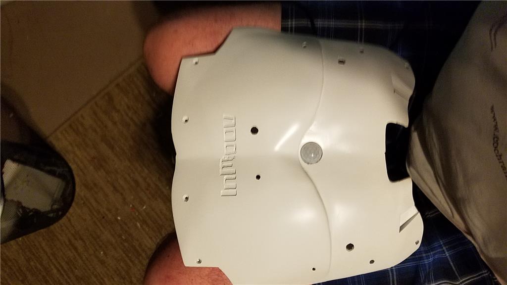
I printed the back door last night. It wasn't on my list so, here is an updated print statistics page. I am done printing until a part breaks I suppose.
PrintStatusInmoov.pdf
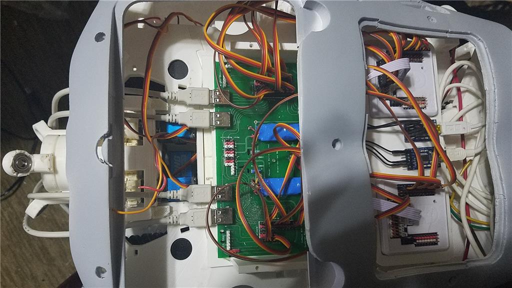
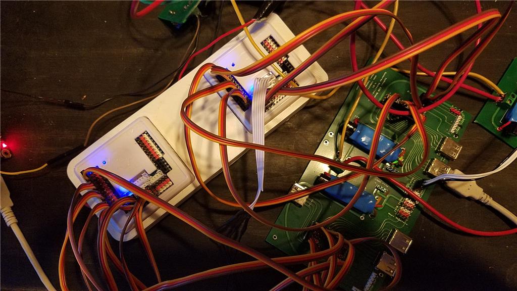
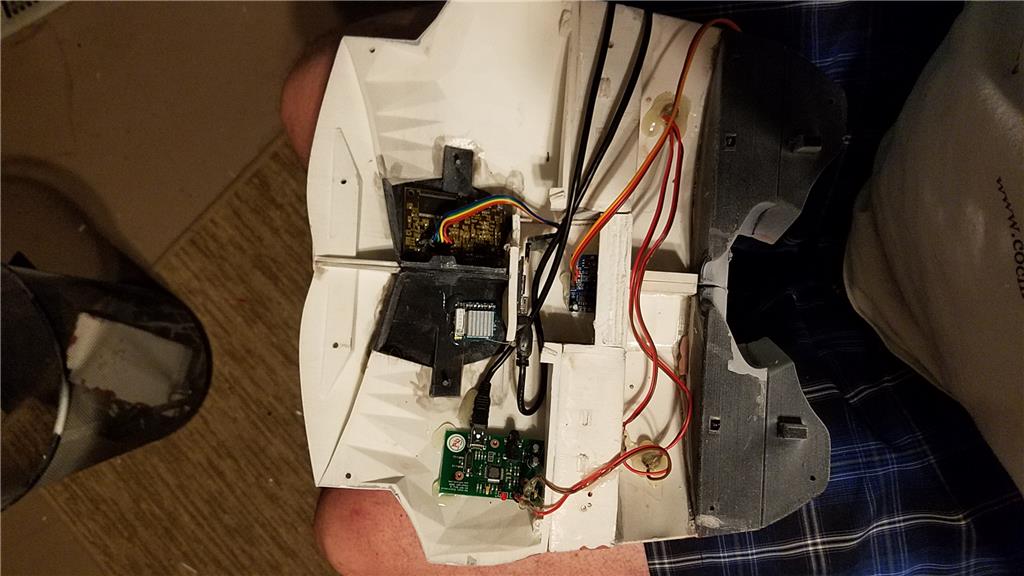
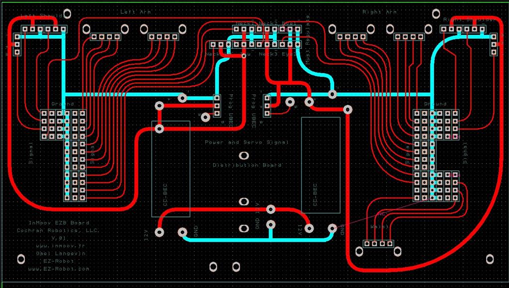
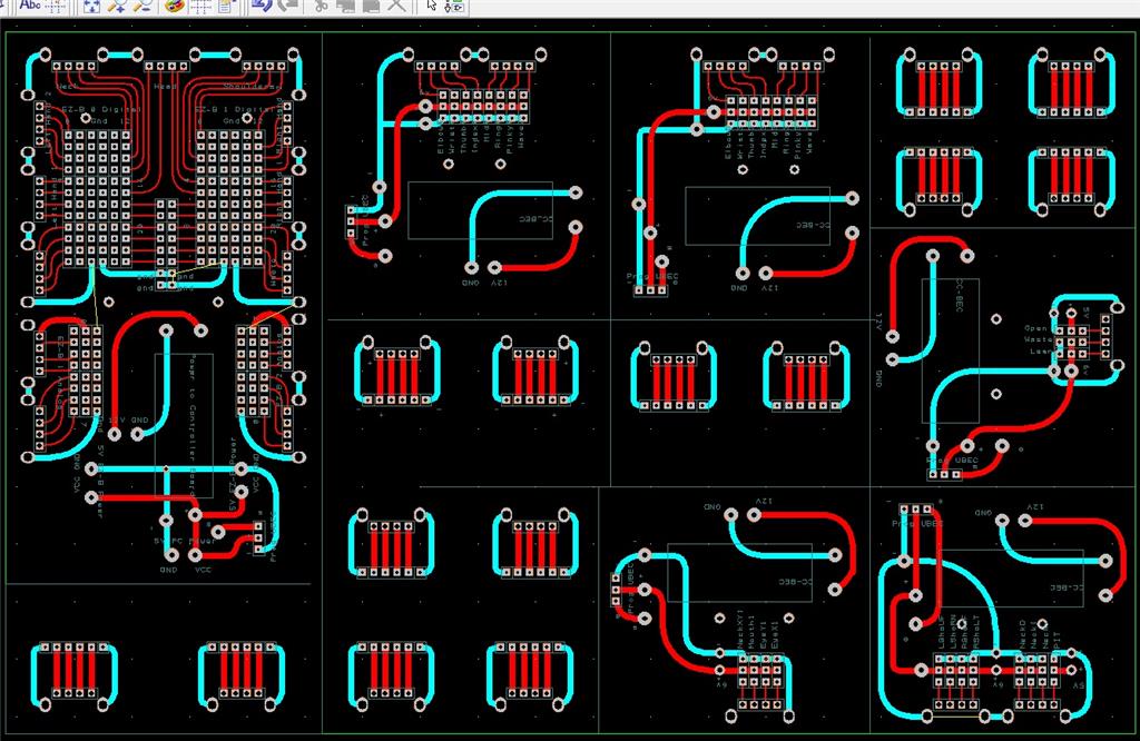
I have designed and have being made a power and servo signal distribution board that will go in the space behind the top door. It will be about a week before I get the board and then will start building it out. The purpose of this board is to supply the correct voltage to the servos and break out the servos into groups with each group powered by their own CC-BEC, with 2 of them being soldered in place on the distribution board. This should prevent brownouts during the inrush when the servos first start moving. The CC-BECs have their own capacitors to hopefully prevent such things.
There are usb type A female connections on these boards to carry the signal to remote boards, such as the lower arms, which have their own CC-BECs. The wires that need to go to the lower arms are 2 USB cables, a positive and negative cable from the 12V battery. This should keep the number of wires needed to run up the arms reduced.
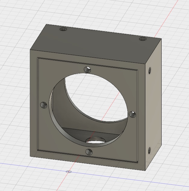
The distribution board will have places for the shoulder, neck and head servos to plug in. The eye servo ports need to be regulated and this is labeled on the board. I will need to plug in a voltage regulator inline that will reduce from 6V to 5V for these as it isn't included on the board. The shoulders and neck servos shouldn't have any problem using 6V, but if they do, these CC-BECs are programmable to allow more voltage to go through to the device. I have include pin headers for the CC-BECs to allow the voltage to be adjusted using the Castle Programmer.
The remote boards (such as those used in the arms) also have CC-BECs on them. This allows different regions of the robot (left lower arm, right lower arm, waist and computer/EZ-B power) to be programmable as far as voltage goes also. These also have pinouts for the CC-BEC's to be programmed. This should allow me to replace almost any of the components with different components and still be able to adjust voltage for that area of the robot.
The power board for the computer/EZ-B's has 2 CC-BECs, which allows different voltages to be used for the EZ-B's and the onboard computer. These will all be placed behind the lower door in the back of the InMoov with the battery being placed in a wheeled platform that I will design, or modify based on what is already on thingiverse to fit the battery that I use.
Here is an image of the board that is being made. I plan to use different color pins to designate ground, power and signal when I build this board.
Fingers are crossed that everything is mapped out correctly on the board. If not, there will be a version .02 Anyway, that's where I am today.
Impressive, thanks for the update.
I'm using adjustable voltage BIC's produced by Castle for the different servos on my B9's arms. They are rated at 10 amps each and are switching style. Kinda expensive but I absolutely love them. They're tiny, very light weight and run cool. After stepping down the voltage from 12vdc to 6 or 7vdc as needed they easily handle the amp draw of my power hungry servos lifting up to 4 pounds while moving fast.
What are these CC BIC's you're using? Sounds simlalur to mine.
Castle Creations BEC's are what I use.
https://www.castlecreations.com/en/bec-voltage-regulator/voltage-regulators-1/cc-bec-010-0004-00
Dave, you are the guy that got me looking at them. I love em.
Yep, it was post #103 of this thread that got me looking at these. Hard to believe that it was 2 years ago...