
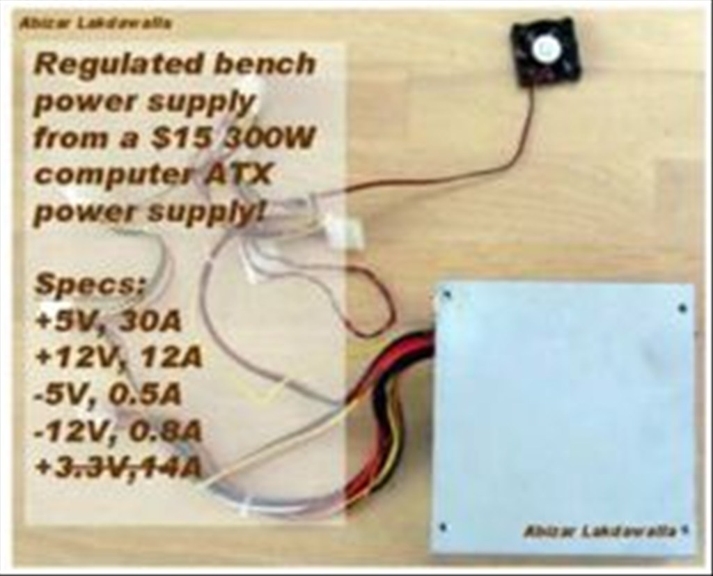
Hello EZ Robot members. I came up with the idea to post this mini project because my roommate needed a power supply to power leds and also 12v fans. Lots of members really need a good high amp dc bench power supply on a budget. My roommate went to a local electronics supplier and recently paid 90 dollars for a 7amp 12v DC power supply. Pc power supplies are generally reliable , handle 15 to 40 amps DC and are 1/5 the price. Take for example the Thermaltake 425 watt TR2 for 30 dollars at Best Buy in the USA.
Safety alert! Capacitors in psu can pop you pretty hard so avoid touching internals of a pc psu even when its not plugged in.
By jstarne1
— Last update
Discover more robots
Jeffmorris's Homemade Biped Robot
Upgrade EZ-Robot hip servos that can't lift biped legs with higher-torque servo recommendations for reliable leg...

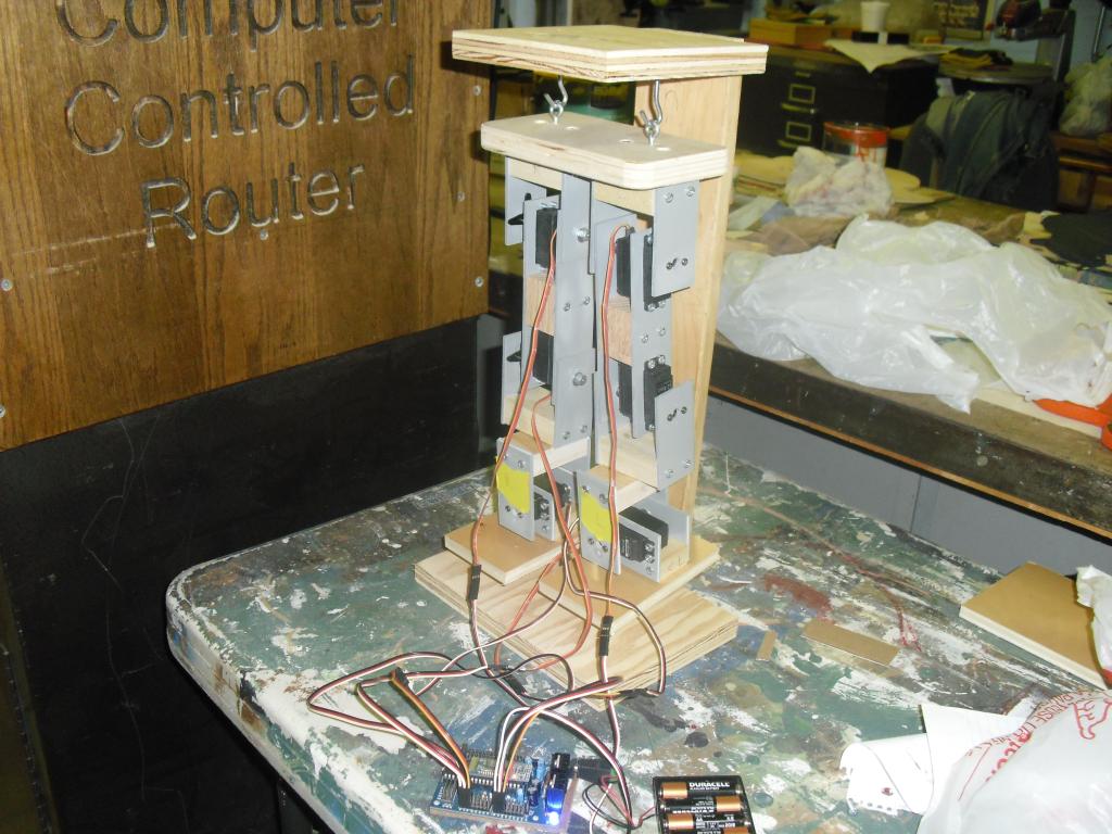
Leversofpower's Omnibot 200 Mod Progress
Control Omnibot EZ-B lighting via Arduino Mega over serial with NeoPixel LED effects, programming progress and...
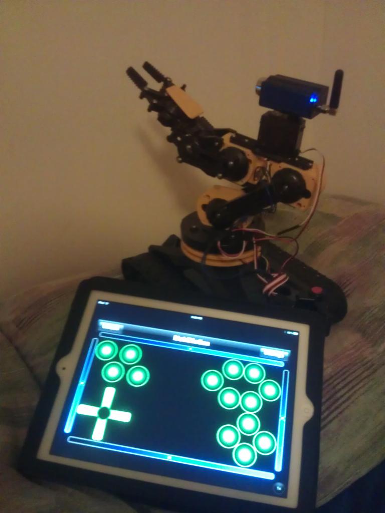
J's Robo Arm
Control a second robot arm from an iPad with the MobiMotion app-drive via accelerometer or joystick; photos show the...

Choose the right psu. Prices have really dropped on pc power supplies so your not limited to used equipment. New power supplies will list three ratings. The important ones are the ones with a positive sign after them. There will be three voltages we are looking at.
12 volt rail - great for bench power supply or source of power for a charging circuit for your autonomous robot. 5 volts - already ideal voltage for ezb and servos. Make your own bench supply to test high torque servos. Also 5v is great for sensors too.
3.3 volts - well leds? Maybe this rail wont be used much
Look online or at your local computer store for an ATX computer power supply, or dismantle an old computer and remove the power supply from the case.
2Unplug the power cable from the power supply and turn off the switch on the back (if there is one). Also, be sure you are grounded so that you don't introduce any static electricity and fry everything.
3Remove the screws that attach the power supply to the computer case and remove the power supply.
4Cut off the connectors (leave a few inches of wire on the connectors so that you can use them later on for other projects).
5Discharge the power supply by letting it sit unconnected for a few days. Some people suggest attaching a 10 ohm resistor between a black and red wire (from the power cables on the output side), however this is only guaranteed to drain the low voltage capacitors on the output - which aren't dangerous to begin with! It could leave the high-voltage capacitors charged, resulting in a potentially dangerous - or even lethal - situation.
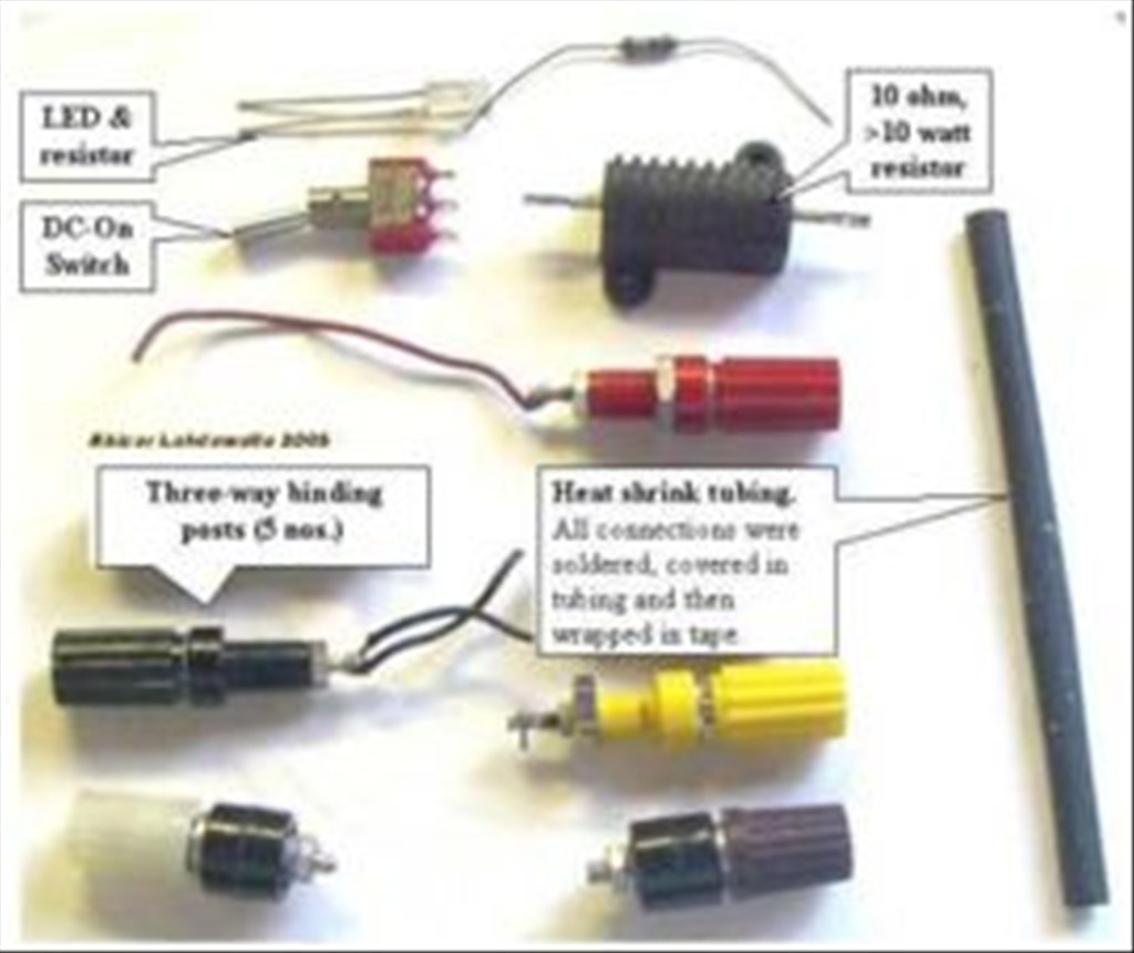
Gather the parts you need: binding posts (terminals), a LED with a current-limiting resistor, a switch (optional), a power resistor (10 ohm, 10W or greater wattage, see Tips), and heat shrink tubing.
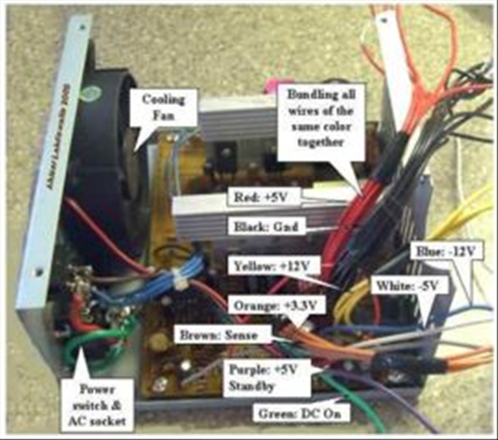
Bundle wires of the same colors together. If you have wires not listed here (brown, etc), see the Tips.
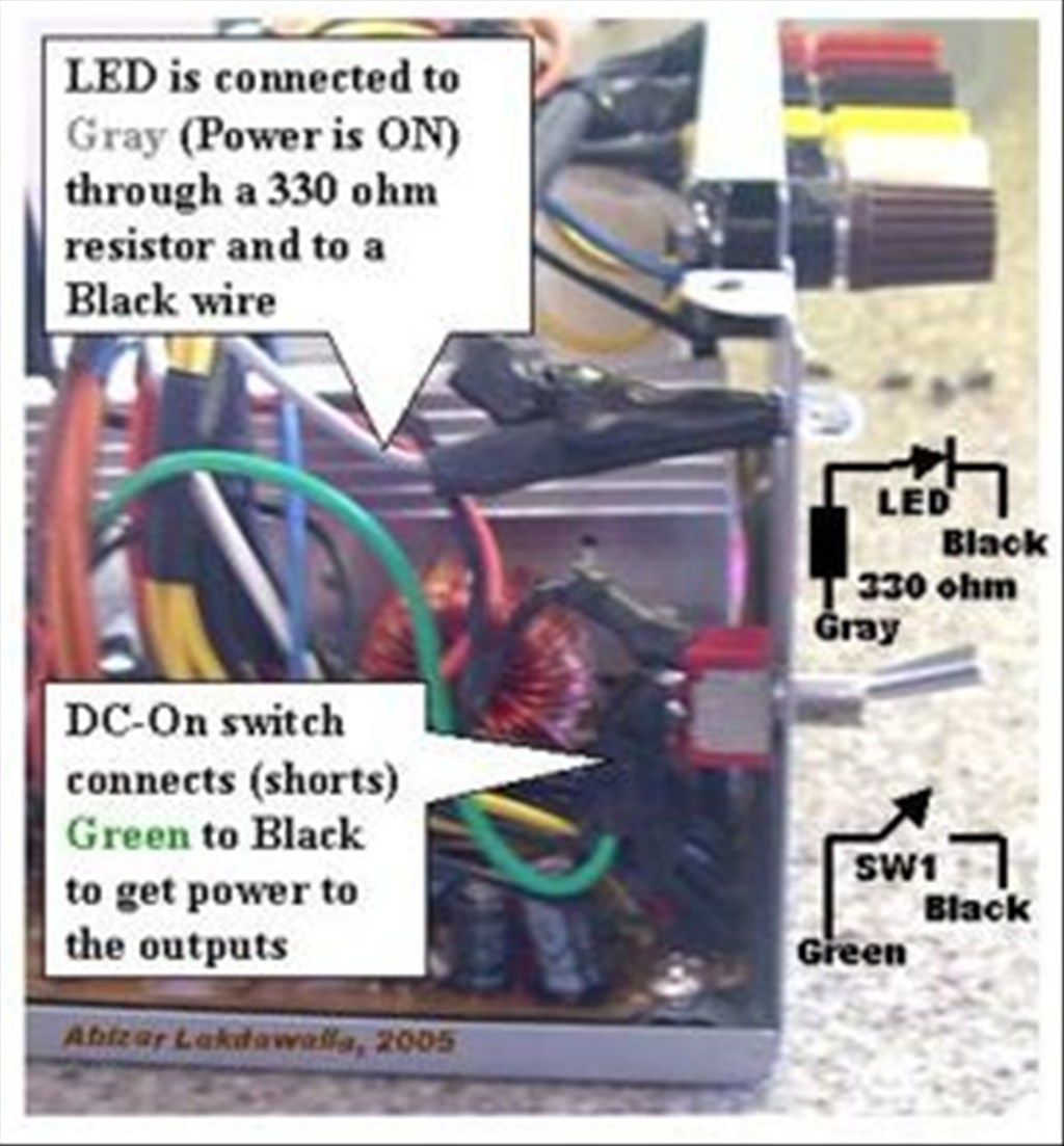
The color code for the wires is: Red = +5V, Black = Ground (0V), White = -5V, Yellow = +12V, Blue = -12V, Orange = +3.3V, Purple = +5V Standby (not used), Gray = power is on (output), and Green = PS_ON# (turn DC on by shorting to ground).
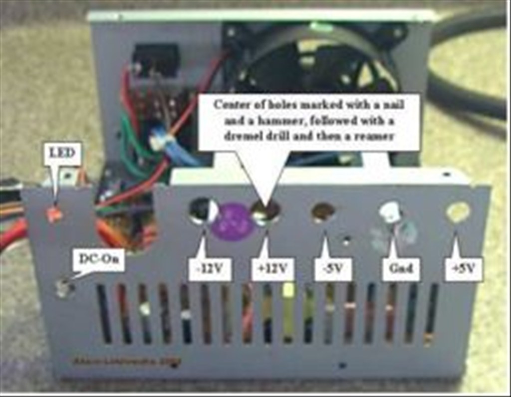
Drill holes in a free area of the power supply case by marking the center of the holes with a nail and a tap from the hammer. Use a Dremel to drill the starting holes followed by a hand reamer to enlarge the holes until they are the right size by test fitting the binding posts. Also, drill holes for the power ON LED and a Power switch (optional).
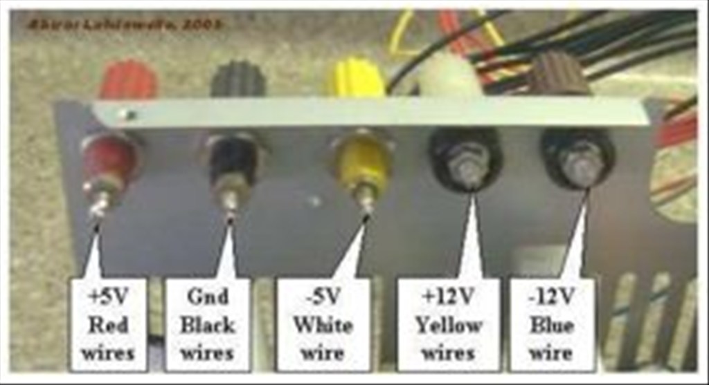
Connect one of the red wires to the power resistor, all the remaining red wires to the red binding posts;Connect one of the black wires to the other end of the power resistor, one black wire to the cathode (shorter lead) of the LED, one black wire to the DC-On switch, all the remaining black wires to the black binding post;Connect the white to the -5V binding post, yellow to the +12V binding post, the blue to the -12V binding post, the gray to a resistor (330 ohm) and attach it to the anode (longer lead) of the LED
-Note that some power supplies may have either a gray or brown wire to represent "power good"/"power ok". (Most PSU's have a smaller orange wire that is used for sensing-- 3.3V- and this wire is usually paired at the connector to another orange wire. Make sure this wire is connected to the other orange wires, otherwise your lab power supply won't stay on.) This wire should be connected to either an orange wire (+3.3V) or a red wire (+5V) for the power supply to function. When in doubt, try the lower voltage first (+3.3V). If a power supply is non ATX or AT compliant, it may have its own color scheme. If yours looks different that the pictures shown here, make sure you reference the position of the wires attached to the AT/ATX connector rather than the colors.Connect the green wire to the other terminal on the switch.Make sure that the soldered ends are insulated in heat shrink tubing.Organize the wires with a electrical tape or zip-ties.12
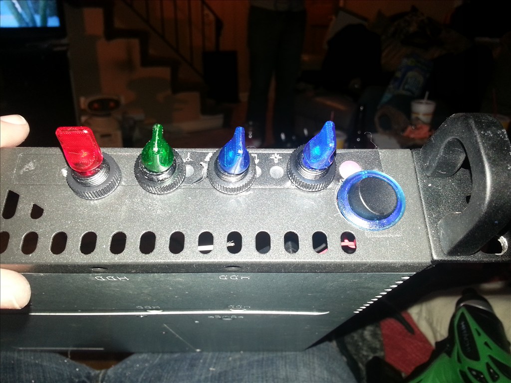
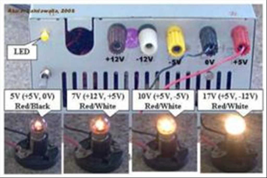
Ok so this pic shows how you can get creative to have a higher voltage if you need. Please be sure to always verify your connection and voltage with multimeter!
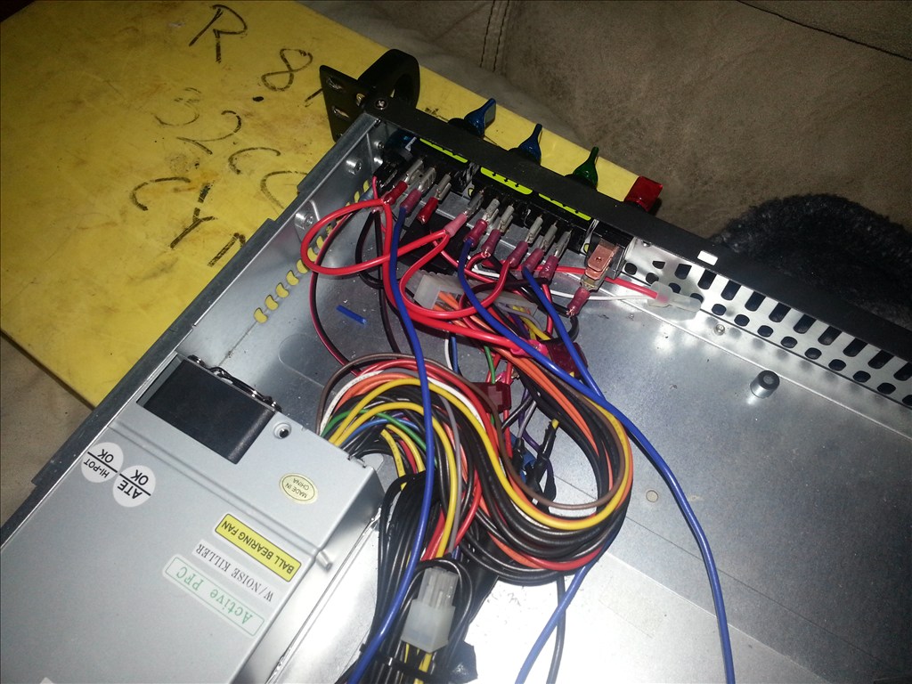
Personally I didnt need all the outputs so I left some unused. Basically the most important trick to the mod to know is connect all the grounds together and connect your greenb wire from atx power connector to a switch and ground on the other side. Turning the switch on powers the psu on as well. I only used 12v pos and 5v pos on the recent smart saltwater aquarium posts.
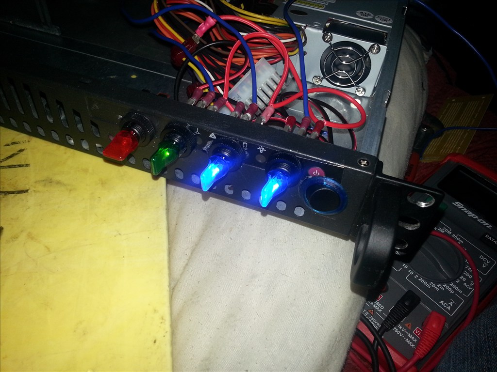
You are right, they can make a great power supply. Just a note, MOST PC power supplies will not turn on unless they are connected to a PC motherboard. If this is the case for your supply then you must make a small work around to make it power up. Look at the 20 or 24 pin main power plug that runs from the power supply. You will see on it one green wire. You need to connect jump the pin from the green wire to a pin on a black wire (any black will work). I just cut a very small piece of wire, large diameter and jump it.
Note: Do this while the power supply is NOT plugged into your wall outlet
Herr
P.S. ... Wow your fast. I started writing this after your second post and you had the rest, with pics up before I finished ... LOL I Didn't know you were going to post how to build one like that only telling others that they can use a PC supply. That is why I mentioned the jumper wire between green and black.
Nice supply. Great work.
Lol yup ! I try to get things together quick unless im having a lazy day. Well today is a lazy day I guess but I still wanted to make a noteworthy contribution to the community today. Many who are new to electronics do not know they could have a potential lab grade power supply in their old computer
Thanks jstarne1 for your articulate article and added pictures! and Herr Ball for the addition
Great tutorial.
But is this image correct?
Unless I have misunderstood, 7v, 10v & 17v all use red/white wires to get the voltage...
Shouldn't it be; 3.3v = Orange/Black 5v = Red/Black 7v = Yellow/Red 10v = Red/White 12v = Yellow/Black 17v = Red/Blue