Battery Charger Docking Project

rgordon

USA

Hello Team,

Well I'm diving in on this project. So it's sink or swim. The discussion thread for Automatic Battery Charger Docking is still open for those who wish to keep brain storming on the topic.

We decided that it would be better to start a separate thread when someone started their build on this project as each one will probably be unique for each individual's home or tastes in design.

I know Fred is doing one Home Base Finding Design Using A Ir Beacon Idea

And I think Technopro is working on one at Ir Autonomous Home Base

So kick back, grab a cup of coffee and try not to fall asleep:D I decided to put down all my thoughts and plans on this subject and work through a scenario (tailored to my home) to help me understand just what will be involved in all this. There will be a bunch of scripting to accomplish this (Rich are you available to assist?) and lots more hardware issues I'm sure. I will en devour to post schematics and pictures as time permits.

Please...please, everyone who dares to wade through all this project, let me know your thoughts and criticisms. Poke holes in my theories, help brainstorm, whatever. All comments are welcome.

By — Last update

ARC Pro

Upgrade to ARC Pro

Experience the transformation – subscribe to Synthiam ARC Pro and watch your robot evolve into a marvel of innovation and intelligence.

United Kingdom
#1  

I'm always available to assist, brainstorm, pick holes etc.

looking forward to this, it should be an interesting challenge.

#2  

Good idea to start another thread,but the last one has some very good idea's that might be forgotten.

On my idea looking at a cheaper way to use the pololu beacon idea,same design only not using the CPU ,but using EZB instead. from the costs of 4 receivers and 6 IR diodes it looks about $10

Using the EZB connections ,looking at 2 ways to use the digital I/O ,one is called multiplexing and other i might use is I2C to digital ,both chips under $1

I ordered the parts i needed ,plus a round pcb from radio shack

This week need to get some scope testing and data from pololu IR beacon

So total cost is about $15

United Kingdom
#3  

I think Rex means this topic is one for his attempt, not a new one for the whole discussion.

The other topic wont get forgotten and I'm (slowly) collating everything that we have come up with so far too so I will pick up all of the ideas.

The original topic is still the place to generally discuss the various ideas, plans, thoughts, suggestions etc.

#4  

Proposed Setup

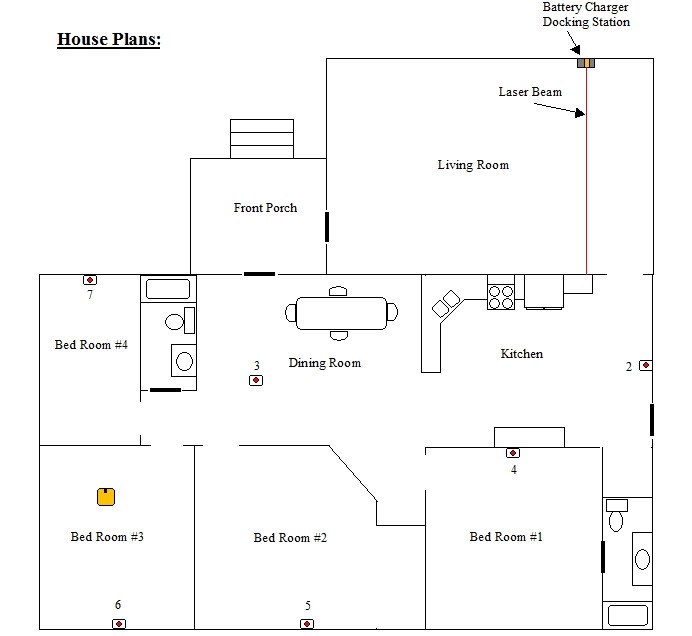
Each room in the house will have its own IR beacon with a unique blink pattern. All IR room beacons will be made using parts from www.rentron.com and will have a low power standby mode to conserve energy while not in use. The IR beacons will be mounted either on a wall or placed on a shelf at a particular height that makes it easy to be seen by the robot's IR receiver. It should be an unobstructed view. The beacons should be constructed so that they are omni directional. Each IR beacon will have a RF receiver that will activate the beacon via a signal from a RF transmitter that is mounted on the robot.

All RF transmitters and receivers will also be from rentron.com. Each RF transmitter will have a unique address code. RF receivers all will have a matching address code so one transmitter controls them all. The RF transmitter will be installed on the robot and will be activated by a digital output from the EZ-B. The RF transmitter on the robot will have its own separate battery supply to keep from using up main battery power while in hunger mode.

On board the robot will be an "omni-cone" reflector that allows the IR detector sensor to see an IR signal from any direction.

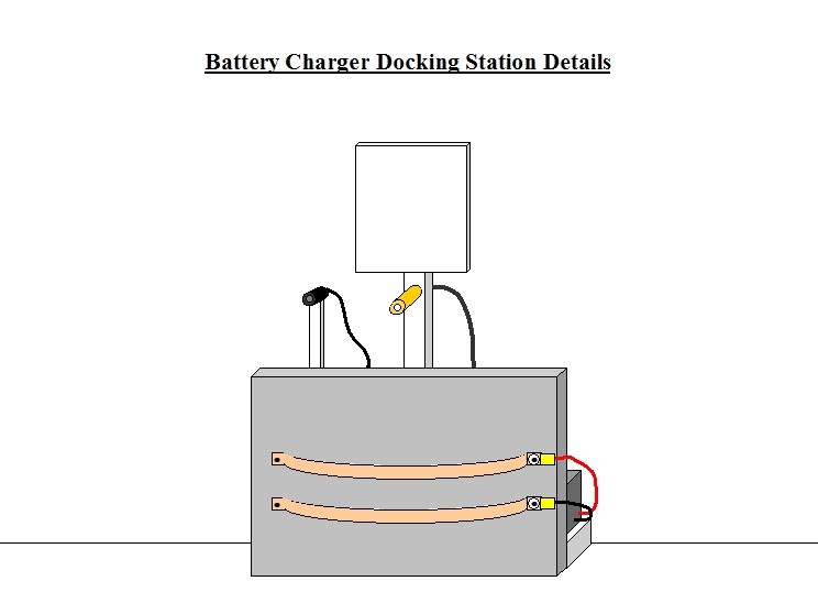
The Battery Charger Docking Station (BCDS) will be located in the Living Room (LR). It will also have a RF receiver with an address that matches the RF transmitter on the robot. When the robot RF transmitter becomes active the receiver on the BCDS and will turn on a laser pointer and a light that will illuminate a glyph symbol mounted on the BCDS. The laser and glyph will be used for guiding the robot into the BCDS. The laser is stationary.

The robot will have a typical array of sensors used for collision avoidance including; IR distance sensors, ping radar, and Ultrasonic Distance Sensors.

There will be a thermopile sensor mounted on the robot that will be used to sense whether an object is living or inanimate. It senses body temperature.

There will be a PIR sensor mounted on the robot to detect motion.

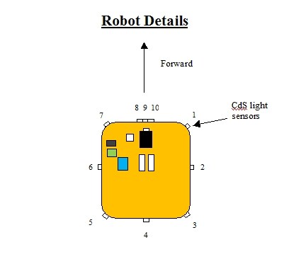
CdS light sensors will be mounted around the perimeter of the robot's mid deck. These sensors will detect the laser beam that shines out from the BCDS. Whenever the laser strikes one of these sensors the robot will stop, then rotate until the laser is shining on the front middle sensor.

IR beacons from www.pololu.com will be used to make it so the robot will follow me around.

Contacts on the BCDS and the robot will be disabled (i.e. not live) until the robot is fully docked for safety reasons.

#5  

Automatic Battery Charger Docking Project 2/27/13 by Rex Gordon

Example Scenario

-The robot is going about its normal activities. -Battery level monitor analog input indicates that the main batteries are low. -A stop command is sent to the Sabertooth 2x12 drive motor controller. Halt all motion. -The robot makes an announcement: "Hunger mode active. Seeking battery charger". -A digital output shuts down all non-essential devices such as: L.E.D. displays, eye
lights, voice lights,etc. If possible. -A digital output activates a RF transmitter located on-board the robot. This transmitter has a 300-ft.range and sends out a signal that activates all IR room beacon receivers and the Battery Charger Docking Station (BCDS) receiver. All receivers have the same address code as the transmitter. So the one transmitter rules them all.

-The IR beacons begin their unique blink patterns:

  Database

   --Bedroom # 4 beacon blink pattern 	 = 7 blinks plus 5 second pause
   --Bedroom # 3 beacon blink pattern  = 6 blinks plus 5 second pause
   --Bedroom # 2 beacon blink pattern 	 = 5 blinks plus 5 second pause
   --Bedroom # 1 beacon blink pattern	 = 4 blinks plus 5 second pause
   --Dining Room beacon blink pattern   = 3 blinks plus 5 second pause
   --Kitchen beacon blink pattern	         = 2 blinks plus 5 second pause

-In the Living Room the BCDS laser pointer is now on and the docking glyph is
illuminated. -Script checks for IR signal blink pattern. -The omni-cone IR receiver digital input detects a repeating blink pattern of 6 blinks then a 5-sec. pause. --Within the script.whenever each IR blink is detected a counter is incremented and a 3sec.wait period (timer) starts. Each time a blink is detected, the timer gets reset to zero and starts over. However, when the beacon gets to the last blink in its pattern, there is a 5-sec pause. This 5-sec pause allows the timer to finish and "time out". When the timer finishes, the script compares the number of blinks stored in the counter to the blink pattern database listed above. The robot has confirmed that it is in Bedroom No. 3 (6 blinks= BR No.3).

-Based on information in the script about the location of the BCDS plus the current compass heading, the robot makes a decision on what direction to take. -A turn command is sent to the Sabertooth drive motor controller. The robot turns and tries to go east (because the script tells it that if you are in BR #3 the only way out is to go east). The script counter is reset to zero.

New directive:

-The robot is now searching for beacon #3. The script ignores all other blink patterns except for beacon #3. It uses wall following techniques and compass heading to find and work its way through the doorway. -After emerging from BR#3 the IR detector starts to see a new blink pattern. -A stop command is sent to the Sabertooth drive motor controller. Halt all motion. -The robot counts three blinks and confirms it is in the Dining Room (DR). -Based on information in the script about the location of the BCDS plus the current compass heading, the robot makes a decision on what direction to take. -A turn command is sent to the Sabertooth drive motor controller. The robot turns and tries to go south (because the script tells it that if you are in the DR the way to the BCDS is south). The script counter is reset to zero.

New directive: -The robot is now searching for beacon #2. The script ignores all other blink patterns except for beacon #2. It uses wall following techniques and compass heading to find and work its way through the next doorway.

#6  

Automatic Battery Charger Docking Project 2/27/13 by Rex Gordon

Example Scenario (continued)

New priority:

-* The Ping radar sensor and forward IR sensor detects an object blocking the path! -A stop command is sent to the Sabertooth drive motor controller. Halt all motion.

Examine object:

-The thermopile sensor input detects the presence of a warm object. (if object temperature is above x degrees then it could either be a pet or a human). The robot makes an announcement: "Excuse me. I need to find my charging dock. May I proceed?" -Wait for proper verbal response: "Yes or OK" -Speech input detects proper response of the word "yes". -The PIR sensor input detects motion. -The thermopile sensor input is now below x degrees. -The forward IR distance sensor input shows all clear ahead. *Note: Ping radar is set so it is only active when the robot is in motion. -The robot makes an announcement: "Thank you." -With the correct verbal response plus all forward sensors showing "clear" then the robot is ok to proceed. -A forward command is sent to the Sabertooth drive motor controller. The robot resumes forward motion. Once again the robot is searching for beacon #2. The script ignores all other blink patterns except for beacon #2. It uses wall following techniques and compass heading to find and work its way through the next doorway. -The robot encounters a new blink pattern. The robot counts two blinks and confirms it is in the Kitchen (K). -Based on information in the script about the location of the BCDS plus the current compass heading, the robot makes a decision on what direction to take. -A command is sent to the Sabertooth drive motor controller. The robot turns and tries to go south (because the script tells it that if you are in the Kitchen then the way to the BCDS is south while following the east wall). The script counter is reset to zero. The script ignores all other blink patterns.

New directive:

-The robot is now searching for the BCDS laser. It uses wall following techniques and compass heading to find and work its way through the next doorway. -The omni-cone receiver analog input has not detected any IR blinks for x seconds. If no IR blinks are detected for x seconds then robot has confirmed that it has entered the Living Room (LR). -Based on information in the script about the location of the BCDS plus the current compass heading,the robot makes a decision on what direction to take. -A turn command is sent to the Sabertooth drive motor controller. The robot turns and tries to go north (because the script tells it that if you are in the LR then the way to find the BCDS laser is north while following the west wall). -The robot encounters the BCDS laser beam: (See Robot Details on page 7) >The robot has 10 CdS light sensors mounted around the perimeter of the middle deck of the robot. Sensors 1 through 7 are all hooked to the same digital input so no matter which one the laser strikes first it will cause the robot to stop and then rotate until it strikes sensor #9. Sensors 8, 9, 10 are each on separate digital inputs. There are circuits on board on the robot that output a digital Logic "1" when the laser strikes a CdS sensor.

#7  

yes i have the thermopile,witch one did you get,also i bought a very good PIR sensor if you look at my brookstone rover project

t hought about using beacons and using a transmitter for each one,first cost is high second i want all sensors on my robot ,and none in any rooms for many reasons

I also have a few other sensor designs for my main robot ,lux sensor and maybe LIDAR

on using CDS you will have a problem with any light hitting it,need something like IR detector to block light

another idea you said i see you are using CDS for is for a laser,what you really need is a LASER photodiode for the wavelength of the laser sensor,this will not let any light in but the laser

#8  

Fred, the CdS circuit is not sensitive to lighting changes. Watch the video at Laser-Detector

Note: I will not be using the latching chip.

#9  

Automatic Battery Charger Docking Project 2/27/13 by Rex Gordon

Example Scenario (continued)

-For this example let's say that the laser is first detected on CdS light sensor # 2. -A stop command is sent to the Sabertooth drive motor controller. Halt all motion. -The robot needs to align the forward CdS sensor #9 with the laser beam. -A command is sent to the Sabertooth drive motor controller to rotate the robot very slowly to the right until the laser beam is detected on sensor #9. Note: The laser beam will also be detected on CdS sensor #1 & #10 as the robot rotates. -The laser beam is eventually detected on CdS sensor #9. -A stop command is sent to the Sabertooth drive motor controller. Halt all motion. -If the path is clear, then a forward at half speed command is sent to the Sabertooth drive motor controller. -If the robot's path drifts to far right or left and the laser beam strikes either CdS sensor #8 or #10, then the script commands the Sabertooth drive motor controller to make a very small course correction (Right or Left) until the laser beam is once again detected on CdS sensor #9. -If the path gets blocked, the script will have to handle the situation and then maneuver the robot to reacquire the laser beam and resume the docking procedure. -When the robot gets close enough that the camera recognizes the docking glyph, the script commands the Sabertooth drive motor controller to slow to minimum speed to reduce chances of damage to the BCDS or robot during docking. -Also when the glyph is detected, the script now ignores all collision sensors except the forward IR range sensor. This sensor plus the docking switches will ensure the robot stops at the correct spot.

Contact with charging dock:

-Docking switch on robot and on docking station actuate. -A stop command is sent to the Sabertooth drive motor controller. Halt all motion. -Turn off RF transmitter. -All IR room beacons, docking laser and glyph light turn off or go into power saving mode. -Power now flowing into batteries. -Script is now monitoring the phototransistor digital input.

Charge complete:

-There is a battery charger, externally mounted, high intensity, Charge Complete L.E.D. mounted on the BCDS that lines up with the phototransistor on the robot. When the charge complete L.E.D. comes on it triggers the phototransistor input to confirm that the charge is finished. The robot announces: "Charge complete. Exit docking station. Please stand clear." -A reverse at minimum speed command is sent to the Sabertooth drive motor controller for x seconds. -Docking switches open. -A turn command is sent to the Sabertooth drive motor controller. The robot turns left for x seconds. -Non-essential systems and collision sensors are turned back on or enabled. -The charging contacts on the robot and the BCDS are now disabled for safety reasons. -The robot resumes its normal activities.

#10  

yes i saw that ,he talking about room light not setting it off,sun light will set it off i guess you need to try it i have a laser diode made for lasers ,no light at all set it off ,i think is $2.42 i paid for it

so would i would do it check different types of lights

whats hard is to try different wavelengths of the spectrum and see if it sets it off,what you dont want is a false trigger to set it off

ONE of the main item i do is look at others who make a design and with testing i made the design alot better without any type of errors

thats one reason my job gives me sensors they design so i can redesign and make it better

#11  

on the thermopile sensor are you using the best one made TPA81 it has 8 thermopile sensors built in

#12  

Thanks Fred for the the thermopile info

Note: You may need to go back and read the previous page as I was entering it when you posted.

#13  

I know this is your post, your idea but you could try using floor map and putting marker on floormap for main room. Then use your sensor idea to guide it there.

#14  

That would be great if it is reliable enough. Do you know how to do this? I am new to scripting and know nothing yet about mapping. Thanks for the info. That's what I want....ideas....ideas....ideas:D

To anyone and everyone reading this post feel free to make any comments or criticisms about any of this stuff. I still have a lot to learn and if someone can save me time and effort I would greatly appreciate it.

Rex

#15  

My design is the same,you make a map and add your furniture,and items in your house,and plan a path using only sensors on your robot,same with home base you also add that to the map this was no other beacon or gyphs or anything else is needed to guide the robot to the home base

i can find the the map info,it is hard to add scripts but can be done ,i do see EZB does have a map feature

They call it path planning

#16  

Automatic Battery Charger Docking Project 2/27/13 by Rex Gordon

Questions (Keep check on this page as I will be adding more questions to it and /or including the answers that I find.)

-Does a compass module just have N, S, E, W or can it also do NE, NW, SE, SW?

-How far away can the camera detect a 4" x 4" glyph?

-What is the best method for using docking switches?

#19  

HEY thats my house is like only just a extra room i have,plus getting ready to buy a little bigger place main reason getting a bigger place,i am getting a ranch to go with it

#20  

So far all my drawings are done using Microsoft Word. Hope to get a CAD program soon.

#21  

Schematics

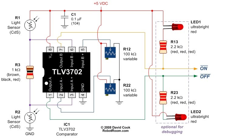
I will attempt to adapt this circuit for use as my laser detector sensor.

User-inserted image

#22  

Thats my favorate type of circuit,its called a window comparator circuit,i use the type in alot of my designs

#23  

Adobe makes one of the best cad software

United Kingdom
#24  

AutoDesk make the best though. What do Adobe make? Can't say I've ever come across anyone who uses adobe for cad, just AutoCAD or Vectorworks.

#25  

yes i mean AUTOCAD from AUTODESK,it very high cost mostly the drafters at work use it

PHOTOSHOP is famous for photo software just like AUTODESK is famous for CAD software

#26  

Ill be glued tio this project so if i see a question i can answer(which is rare) i can help.

Going to take a look at that floor map design i was talking about.

#27  

Need a way to modify the floor map image and feed it back into floor map. Can save the image but no way to put it back in.

Now please turn your attension to @rgordon

#28  

Have not been able to get time to work on my project lately :( Trying to get our rental house ready for the next family to move in. It seems to be an endless amount of things to fix or clean up. We have two rental houses and our house. I hate being a landlord. But the wife seems to think I never give out of energy or don't need any time for myself. tired

Hopefully I will be able to work on my project soon. Got to save up some "squirrel" money to buy the parts for the IR beacons and transmitters.

Thanks guys for your contributions and support on this project. Please don't give on me.

The multiple color tracking is a wonderful new tool but, I don't think it would work in my home for the auto docking project due to the lighting conditions. Seems to me that the camera needs extraordinarily bright lighting to track things properly. Maybe its just I have not found the right combination of settings yet IDK.

Rex

Spain
#29  

You thought illuminate the field of view with a high brightness light on the robot? Could be activated only when the camera HELD color tracking. I'm amazed at how much light the torch of my cell phone, as just a hyper bright LED, perhaps with the appropriate distance between the light and the color of the robot to recognize they could correct the problems by poor lighting or mood lighting.

#30  

SAME with me i wont be able to finish my projects for awhile till i get back from my work trip my robots going to miss me for awhile :(

BUT house stuff and work comes first

United Kingdom
#31  

@R2D2 My robot has 2 high powered LED lights for eyes which light his way in the dark, these are to the sides of the camera so you would think it could illuminate for vision however it does not. When really close it shows as white on the camera due to reflection, too far away and it doesn't help at all.

@Rex, tinker with the settings, you can change the brightness etc. I had to on mine as it is very dim in my house (warm white lamps, a more comforting surrounding, not task lighting at all) but it still catches phantom faces for face detection.

#32  

Rich, have you had time to wade through any of my docking example? How hard (or is it possible) to make a script to count the number of blinks of the IR beacons as described in my example. See page 1 post #6.

United Kingdom
#33  

Not yet I haven't, I've been short on time lately with working 18 hour days so have only had a quick look. Will look properly when I get chance though.

#34  

Here is yet another Ir beacon I have discovered while cruising the web. It is a LEGO approved sensor that may be of some use to us. If we could find a way to use it with EZ-B.

IR beacon

#35  

Idea i have planed after my EZB beacon design is like a LIDAR but uising one IR receiver in continuous turning turret and picking up 16 points of data, using whats called S&H circuit

The design is a little tricky only because after 360 deg the wire will break off,so it needs like the LIDAR design is using or like the design a hard drive has,magnetic reveiver and transmitter

#36  

What if the robot is in an area where it sees two blink patterns overlapping? If the script is configured so that it is ignoring all other blink patterns except the one it is looking for then maybe it will be OK? Say for instance it is in the Dining Room getting near the entrance to the Kitchen area (see floor plan dwg.)and it is seeing two beacons at the same time. At this point (trying to find the Kitchen) it is looking for two blinks and a 5 sec. pause. If it is seeing the two blinks from the beacon in the Kitchen and still seeing the three blinks from the Dining Room the timer does not have time to reset so it will ignore it until it gets to a place it is only seeing two confirmed blinks and a 5 sec. pause. .....I think......(see page 1, post # 6 for my idea on how the blink counting would work)

Help me out here guys...am I totally off my rocker here?

United Kingdom
#37  

Very quickly scanned over that and I may have the wrong end of the stick so excuse it if I have but you want a priority list of beacons... for instance;

Order of priority

  1. Kitchen
  2. Dining
  3. Living
  4. Hall

(Room names are not specific to your project, I am just getting the general idea across).

If that's the case you need the IFs in the right order...

This isn't the code (in a rush, will expand later) but it's something like...

IF(Kitchen Detected) Move to Kitchen ElseIf(Dining Detected) Move to Dining ElseIf(Living Detected) Move to Living ElseIf(Hall Detected) Move to Hall Else Keep Searching EndIf

That will first look for the kitchen, ignoring all else. Then the dining if kitchen isn't found... etc.

#38  

Hi Rich,

From my example: Say the omni-cone IR receiver digital input detects a repeating blink pattern of 6 blinks then a 5-sec. pause.

Within the script,whenever each IR blink is detected, a counter is incremented and a 3sec.wait period (timer) starts.

Each time a blink is detected, the timer gets reset to zero and starts over. However, when the beacon gets to the last blink in its pattern, there is a 5-sec pause.

If no more blinks are detected, this 5-sec pause allows the timer to finish and "time out". When the timer finishes, the script compares the number of blinks stored in the counter to the blink pattern database listed on page 1 post # 6.

The robot has confirmed that it is in Bedroom No. 3 (6 blinks= Bed Room No.3)

When the robot determines what room it is in then based on the info contained in the script database it makes a decision on which direction to move and what beacon to seek next. The counter is cleared and ready for the next count.

Can timers and counters be used within a script? I have not checked yet.


My main concern is what I mentioned earlier; it could possibly get to a point in its journey where it would encounter blinks from two beacons at the same time. This would be when it is in the Dining Room and nearing the entrance to the Kitchen.

If it is seeing the two blinks from the beacon in the Kitchen and still seeing the three blinks from the Dining Room the script timer would not have time to reset. So it should ignore this situation until it gets to a place it is only seeing, what it is currently seeking at that point in the journey, which is two confirmed blinks and a 5 sec. pause.

I hope all my babbling makes sense :D

United Kingdom
#39  

Yes counters can be used. I don't know how the IR beacons and sensor are working (or planned to work) but if for argument's sake it sets a digital port to on when detected...


IF(GetDigital(D0) = 1)
  $Counter = $Counter++
EndIf

That would increase the value of the variable $Counter by 1.

You could throw in a Digital_Wait (digitalPort, on/off/true/false) command to only run the code when a blink is detected too.

However, something that just sprung to mind and needs to be gotten around is this... What happens when the robot "sees" the beacon part way through it's blink cycle? If it's a beacon which blinks 8 times and then a 5 second pause but the robot catches it half way through it will count 4 blinks then a 5 second pause.

A way around that would be to check at least twice, if the count doesn't match then count a third time to determine the correct count. Or you could wait for a 5 second pause before counting. I'd have to think about how to achieve that though.

But it also leads back to "What happens if the robot detects two beacons at once"... It would count both... and since the blinks and 5 second pause would last different periods of time on each beacon it could result in a very large count. I'm unsure if there is a way for it to determine when it's only reading one beacon.

It's very probably going to be a complicated script and system. Are there any alternatives? Different constant blink rates, like different frequencies (which it basically is). 1 blink per second, 2 blinks per second and so on.

I still need to read through this topic properly as I'm rather blind looking at this and the things above may have already been thought of or gotten around. Hopefully I will have more time to look soon but this week is hectic with work.

#40  

Thanks Rich...yeah I know the feeling...."me" time is something that is hard to come by.

You may need a large cup of coffee to wade through all my ramblings on this topic. I'm not sure if this will work or not. I may have to try to find a way to send a three bit digit using the Fire Stick circuit from rentron.com. But I guess it will still have the issue of seeing more than one beacon.....

Quote from Star Trek...."Time is the fire in which we all burn"

#41  

REX how i look at i never give up,i keep at it until i get it working

There a good breadboard helps ,if the design doesnt work chage a few parts and try again

THEN put on a protoboard,with me i have it a little easy,since i have almost any test equipment made most common is multimeter,scope and frequency counter and generator

#43  

@Technopro,

Thanks for the link. I will consider it. The price is good. Need to find out more about it. Looks like it could be used easily with the EZ-B.

#44  

yea any time. Dj said that serial ir recievers/transmitters will be compatible later on with the revolution so stay tuned.

#45  

TECHNOPRO ,i saw them on ebay before only bad about them they use the same IR frequency as a remote does ,and if you are using remote it will have problems

POLOLU IR beacon uses 56 khz to not have that problem ,and parts are the same cost or less

I got my parts for both receiver and transmoitter at $5 total and saved $4 plus same design going on ebay for $9