

Thought I would share my progress so far converting my old 4WD project over to using my new EZ-B controller. Over the last year or so, I have had it running on an Arduino Mega using Xbee RF modules for communications.
I had an on-board 2.4ghz camera but always had problems with it knocking out my Xbee communications (also 2.4ghz). Lately I tried Synapse RF modules instead of Xbee but had similar issues. I don't think I'll have any problems using the EZ-B camera and Bluetooth communications. But at some point, I want to change the EZ-B's Bluetooth adapter over to Synapse, as it can work out to several thousand feet line of sight.
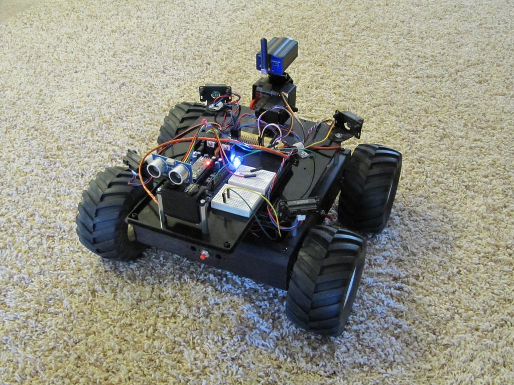
Here's how the 4WD is outfitted: (1) Sabertooth 2x12 motor controller; (4) Gearhead 12V, 30:1, 200rpm motors; (1) 12V 2800mAh battery; (4) Sharp GP2Y0A21YK0F IR Range Sensors; (2) Quadrature Motor Encoders.
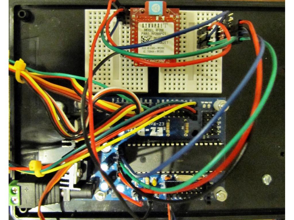
The Sabertooth and battery pack are located in the base. The Sharp range sensors, EZ-B ultrasonic sensor and camera are not connected in the photo, so don't give me a hard time about all the loose wires.
I never got around to installing the motor encoders or doing any more with the Sharp range sensors than testing them. The motor encoders will eventually be used to keep track of distance travelled.
Here's where I'm at this point in the new project: I have the Sabertooth motor controller connected and working with the EZ-B much to our dog's frustration. Reminds me, I need to add the ability for the 4WD to bark.
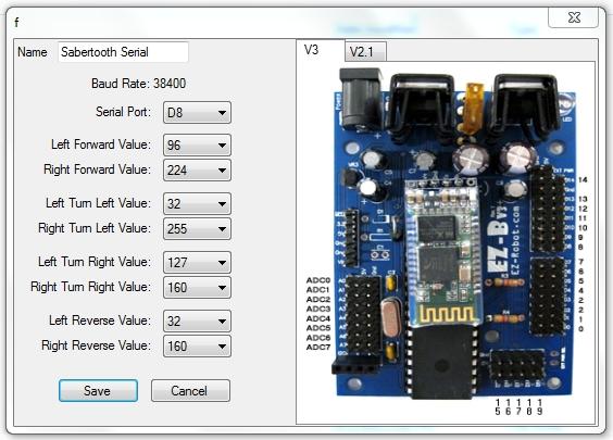
The Sabertooth swiches are set for Mode 3 Simplified Serial at 38,400 baud (1,3, & 6 ON). The EZ-B is getting its 12VDC power from the same battery as the Sabertooth, so their grounds are tied together through the battery connection. The only other connection is one wire from the Sabertooth S1 terminal to the EZ-B's D0 port.
Because I have both of my left motors are connected to the Sabertooth's Motor #1 output and both of my right motors are connected to its Motor #2 output, I had to change the settings in ARC's HBridge Sabertooth Panel as follows:
Full Forward Left 127 Right 255
Turn Left Left 1 Right 255
Turn Right Left 127 Right 128
Full Reverse Left 1 Right 128
It goes forward or reverse about 10 feet per second with these settings. It can rotate or turn on a dime and would no doubt eventually tear a hole in the carpet, which my wife says will cause something even worse to happen, depending on who she catches first. Really, those tires mounted to those motors can do some serious turning when one side goes full forward and the other side goes full reverse.
Next up will be making the EZ-B ultrasonic ranging sensor work with my 4WD. I have tested the ultrasonic sensor by itself, and it works great. It looks like it can sense 3-4 times farther out than the Sharp sensors.
Until next time.
Other robots from Synthiam community
Nolan's Nolan's First Robot
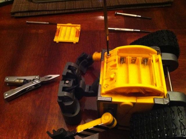
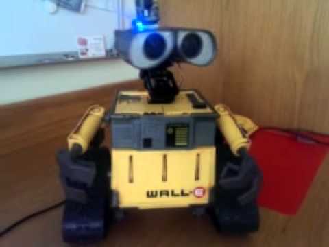
Daman's Yet Another Wall-E

Great write-up Marv! That's a heavy duty robot
I don't think there has been any interference reported with the ez-robot camera and synapse. You should be good to go! That'll make a fun spy robot... Have you looked at the Vuzix glasses we use for Augmented Reality? I used my brookstone rover, sat in a chair and drove it down the street into someone's back yard one day. It's such an adventure! Totally new experience
That is amazing! Guess I'll have to work that into next year's budget somehow. Even now, once I get it connected with one of my Synapse RF266 modules, I should be able to run the 4WD around our cul-de-sac while I sit inside at my computer. How far does the video camera you sell reach? Would it work out to maybe 150' with a couple walls in between?
By the way, I sent a problem report to the "Contact Us" link about my new video camera. It looks like I'm having the same problem steve3624 and lordhotwing mention on the forum. For now I'm just using one of my old wired usb cameras for testing.
A4WD Project Phase 2
Didn't take long to realize it's safer to test my motor configuration setting math with the A4WD sitting on a book. I'm using two EZ-B control panels for this test. One config's the servos, where I can input specific values for my Sabertooth motor controller, as far as speed & direction. The other panel config's the ultrasonic sensor where I can set the detection distance for obstacles, delay for turning and reversing. I have it set for 20" for this test. You'll notice it's scanning 180 degrees of the horizon looking for potential targets, but its head stops scanning or moving if it detects the enemy, in this case a fly swatter.
You can see and hear the left motors react when the ranging sensor sees something to its left. Same thing on the right. An obstacle in the center causes both motors to reverse. The fly swatter confuses it a little, because it can't physically move to avoid the fly swatter. But... I could just as easily charge forward while firing a paint gun instead of retreating
allenconnections.com/video/A4WD_Phase2.mp4
Here's a link to a blog I setup to post my A4WD/EZ-B project's progress.
A4WD RoboBlog
Nice bot! And welcome to the forum!
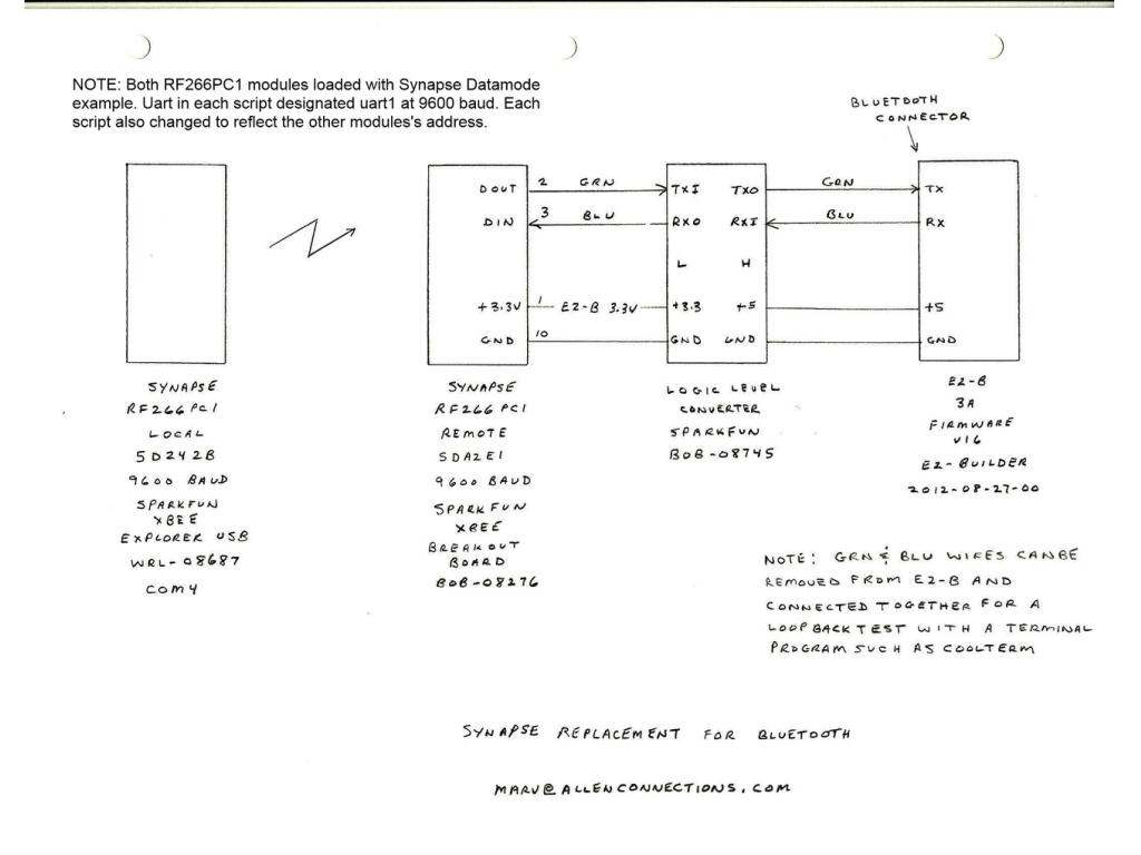
After hitting a few pot holes along the way, I now have the EZ-B in my 4WD comminicating with Synapse RF266PC1 modules instead of Bluetooth. Synapse's datasheet for the RF266PC1 rates them at 4,000 feet line of sight. I'm expecting much less in the real world and plan to do some distance testing this weekend.
I'm sort of a pragmatic person, so I started by setting things up first by replacing the Bluetooth with just a simple FTDI setup. Once I had that going, I set it up with a pair of Xbee's, which are a bit simpler than Synapse modules. They are configurable but don't run a (Python) script like the Synapse modules.
So, then it was on to the Synapse modules. That's where I hit a couple pot holes. The Synapse RF266PC1's are plug compatible with Xbee's (at far as the essential pins for uart communications), and I have a collection of Xbee adapters. Once I had scripts loaded in each Synapse module, it should have been as simple as just plugging them in instead of the Xbee's. But that was not to be.
Some Synapse modules have two uarts designated 0-1. The main issue was I assumed the single uart in the RF266PC1 would be designated uart0. Silly me. The RF266 requires use of uart1 in its Python programming.
Another issue was the script I modified was actually an example provided by Synapse for some of their other modules. The RF266PC1 is a new product, and some of the documentation is a bit behind release of the product.
Many thanks to J.C. Woltz on the Solarbotics forum for showing me the light.
Anyway, all's well that ends well. Now I can run my 4WD Rover around the neighborhood with my laptop. hmm... may have to have some kind of auto kill switch in case I loose sight of it.
With long range communications now established with the Synapse modules, it was time to move on to controlling my 4WD Rover with a joystick connected to my notebook PC. I chose a direct USB cable connected model over a wireless one, since I intended to have the notebook PC within arm's reach anyway.
I found a good buy on a Playstation 3 Afterglow AP1 from Performance Designed Products (PDP) at Wal-Mart.
Then I mapped the buttons using EZ-Robot's Joystick Control Panel. The cross button to the left must be out of range of the Joystick Control Panel's button list, as those particular buttons never show. That's ok. There are more buttons than I have fingers. The numbers match to the button list in the Joystick Control Panel.
I only used two panels for the following tests shown below. The Joystick Control Panel and the Sabertooth Movement Panel. The #1 (left) joystick controls the drive motors, and the #2 (right) joystick controls head movement, up/down, left/right. The gripper jaws and up/down movement are controlled by the 4 buttons on the right side. The 3 buttons in the center control rear IR sensor movement.
It took some trial & error to set the min/max servo positions to keep the servos in a practical range of movement. For example, setting the gripper up/down servo max too high results in lifting the Rover's front wheels off the floor. I have learned to start with min/max settings in a very safe range before increasing them to prevent damage.
Video - Controlling the A4WD Rover with a Joystick
Welcome to the forum Marv! Your project is fantastic, spy or surveillance robot! You've just arrived and has already made a good contribution to all that want to install modules synapses. Keep it up.