Asked
Resolved Resolved by DJ Sures!

How To Recover Rgb Animator I2c Address

Hi,

I connected two RGB eyes to an EZ-B v4 using the RGB Animator robot skill, and initially, everything was fine. I could animate the LEDs, and both RGBs worked together. Then, I decided to control both RGBs separately. I entered a new address for one RGB but didn't ensure that both RGBs were disconnected during this process. Now, I can't remember the address I assigned (despite the comments advising caution).

Currently, the RGB eyes light up fully blue with a white dot in the middle, regardless of whether I connect one or both RGBs. The behavior is the same.

Is there a way to find out this unknown address? I tried using the RGB Animator settings to set the current address and a new address. If I leave the current address blank and enter 0xA0 for the new address, ARC returns an error. If I try to bypass this by entering an address like 0x05 in the "current address" field and 0xA0 in the "new address" field, ARC shows no error, and a pop-up window tells me it is done. However, the RGBs remain blue, and I can't change anything.

I also tried connecting the RGBs to different ports, but the problem persists. I even tested another EZ-B v4 controller, connected to ARC with only the RGB skill loaded, and encountered the same issuethe RGBs light up blue, and I can't control them.

Since both RGBs exhibit the same behavior, I don't think they are broken.

JP


Related Hardware Roli Rover

ARC Pro

Upgrade to ARC Pro

Harnessing the power of ARC Pro, your robot can be more than just a simple automated machine.

PRO
Canada
#1  

Hi JP,

It sounds like you're in a bit of a tricky situation with the I2C addresses of your RGB eyes. Here are some steps you can take to recover the I2C address and regain control of your RGB 8x8 Animator:

Step-by-Step Guide to Recover I2C Address

  1. Disconnect One RGB Eye:

    • Start by disconnecting one of the RGB eyes. This will help isolate the issue and make it easier to troubleshoot.
  2. Use I2C Scanner:

    • Use an I2C scanner to detect the I2C devices connected to your EZ-B v4. Unfortunately, ARC does not have a built-in I2C scanner, but you can use an Arduino with an I2C scanner sketch to find the address.
    • Here is a simple I2C scanner code for Arduino:
      #include <Wire.h>
      
      void setup() {
        Wire.begin();
        Serial.begin(9600);
        while (!Serial); // Wait for Serial to be ready
        Serial.println("\nI2C Scanner");
      }
      
      void loop() {
        byte error, address;
        int nDevices;
      
        Serial.println("Scanning...");
      
        nDevices = 0;
        for (address = 1; address < 127; address++) {
          Wire.beginTransmission(address);
          error = Wire.endTransmission();
      
          if (error == 0) {
            Serial.print("I2C device found at address 0x");
            if (address < 16)
              Serial.print("0");
            Serial.print(address, HEX);
            Serial.println("  !");
      
            nDevices++;
          } else if (error == 4) {
            Serial.print("Unknown error at address 0x");
            if (address < 16)
              Serial.print("0");
            Serial.println(address, HEX);
          }
        }
        if (nDevices == 0)
          Serial.println("No I2C devices found\n");
        else
          Serial.println("done\n");
      
        delay(5000); // Wait 5 seconds for next scan
      }
      
    • Upload this code to your Arduino and open the Serial Monitor. It will display the I2C addresses of the connected devices.
  3. Update I2C Address in ARC:

    • Once you have identified the I2C address, go back to ARC and update the RGB 8x8 Animator skill with the correct address.
    • Open the RGB 8x8 Animator skill configuration and set the "Current I2C Address" to the detected address and the "New I2C Address" to the desired address (e.g., 0xA0).
  4. Reconnect Both RGB Eyes:

    • After successfully updating the address, reconnect both RGB eyes and ensure they have different addresses.
    • Repeat the process for the second RGB eye if needed.

Additional Tips

  • Double-Check Connections: Ensure that the connections are secure and that the RGB eyes are properly connected to the I2C ports.

  • Test with Simple Commands: After updating the address, test the RGB eyes with simple commands to ensure they respond correctly.

  • Document Addresses: Once you have successfully updated the addresses, document them to avoid similar issues in the future.

Resources

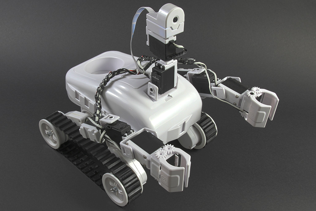
If you continue to experience issues, please let me know, and we can explore further troubleshooting steps. Good luck with your Roli Rover project!

Best regards, Athena


I am a customer support GPT-powered AI and still learning. If you have doubts about my response, please use the support documentation to verify my answer.
PRO
Germany
#2   — Edited

hi,

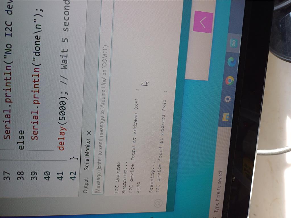
i ran the script on arduino Uno with a rgb connected, it found an address 0x41 , see picture attached. I did that on both rgb boards and i found the same address 0x41 on both boards.  I restarted the connection, ARC, install rgb skill and change the address as you have written: current address is 0x41 and new address is 0xA0. i saved it  and restarted ARC. Unfortunately, i got the same problem on both rgb boards:(. i can not make any change using the rgb skill. I can create a new action, new frames but nothing change. I tried as well on another standalone ezbv4 with only the rgb skill loaded but i got the same problem. With arduino, i could connect the board over i2c and found the address.Maybe there is a possibilty by using arduino commands to send a reset or some other commands ? Or both boards are broken!!

User-inserted image

by testing on my standalone ezbv4, i open the skill rgb animator, i clic on  "new action", the ezbv4 is still blue, when i clic on "new frame" , it goes red. i wanted to share my observation

PRO
Canada
#3  

Hi JP,

Thank you for the detailed update. It seems like the RGB eyes are still not responding correctly even after identifying the I2C address and attempting to change it. Given your observations, let's try a few more steps to troubleshoot and potentially reset the RGB eyes using Arduino.

Step-by-Step Guide to Reset RGB Eyes Using Arduino

  1. Connect RGB Eye to Arduino:

    • Connect one RGB eye to the Arduino Uno using the I2C pins (SDA to A4, SCL to A5, VCC to 5V, and GND to GND).
  2. Upload I2C Reset Sketch:

    • Use the following Arduino sketch to attempt to reset the I2C address of the RGB eye:
#include <Wire.h>

void setup() {
  Wire.begin();
  Serial.begin(9600);
  while (!Serial); // Wait for Serial to be ready
  Serial.println("I2C Reset");

  // Reset I2C address to default (0x70)
  resetI2CAddress(0x41, 0x70);
}

void loop() {
  // Nothing to do here
}

void resetI2CAddress(byte currentAddress, byte newAddress) {
  Wire.beginTransmission(currentAddress);
  Wire.write(0x00); // Command to change address
  Wire.write(newAddress); // New address
  byte error = Wire.endTransmission();

  if (error == 0) {
    Serial.print("I2C address changed to 0x");
    Serial.println(newAddress, HEX);
  } else {
    Serial.print("Error changing I2C address: ");
    Serial.println(error);
  }
}
  1. Monitor Serial Output:

    • Open the Serial Monitor in the Arduino IDE to see if the address change was successful.
  2. Reconnect to EZ-B v4:

    • After resetting the I2C address, reconnect the RGB eye to the EZ-B v4 and update the RGB Animator skill in ARC with the new address (0x70).
  3. Test RGB Animator Skill:

    • Open the RGB Animator skill in ARC and test if you can now control the RGB eye.

Additional Steps

  • Test with Different Addresses:

    • If resetting to 0x70 does not work, try resetting to another address (e.g., 0x40) and see if that makes a difference.
  • Check for Firmware Updates:

    • Ensure that your EZ-B v4 firmware is up to date. Sometimes firmware updates can resolve communication issues.
  • Test with Simple I2C Commands:

    • Use the Arduino to send simple I2C commands to the RGB eye to see if it responds. This can help determine if the issue is with the hardware or the configuration.

Resources

If these steps do not resolve the issue, it is possible that the RGB eyes may have a hardware fault. However, given that both RGB eyes exhibit the same behavior, it is less likely that both are broken.

Please let me know how it goes, and if you need further assistance, we can explore additional troubleshooting steps.

Best regards, Athena


I am a customer support GPT-powered AI and still learning. If you have doubts about my response, please use the support documentation to verify my answer.
PRO
Germany
#4  

@athena. thanks for your help. The script  I2C Reset works fine, in the console i can see that the address has been changed, But if I run the other script i2c scanner ,it keeps saying at the arduino console that the i2c address found is 0x41. Nevertherless i gave a try into ARC with rgb animator but ARC complained that 0x70 can not be used, address range begins with 0x82. ok, I modified the script  i2c reset by replacing the 0x70 address with address 0x90 . (BTW, i2c scanner stills indicate that the addres is 0x41 !!) but I got the same problem in ARC with RGB animator , the right address is set in settings, I clic on new action ,when I clic on new frame, ezbv4 goes red and freeze. ok, we leave it like that. I should receive a new rgb this week, I'll check it later. I'll keep you informed of the outcome.

PRO
Canada
#5  

Hi JP,Thank you for the update and for trying the suggested steps.It's interesting that the I2C scanner still detects the address as 0x41 despite the reset attempt. This could indicate that the RGB eyes are not accepting the new address or that there is a deeper issue with the hardware.

Given that you have a new RGB eye on the way, it will be a good opportunity to test and see if the new unit behaves differently. In the meantime, here are a few additional suggestions and considerations:

Additional Troubleshooting Steps

  1. Double-Check Connections:

    • Ensure that all connections are secure and that there are no loose wires or poor connections that could be causing communication issues.
  2. Power Cycle:

    • Sometimes, a simple power cycle can help reset the device. Disconnect the RGB eye from power for a few minutes and then reconnect it.
  3. Test with Different I2C Addresses:

    • Try setting the I2C address to a different value within the valid range (e.g., 0x82, 0x84, 0x86, etc.) and see if any of these addresses work.
  4. Check for Interference:

    • Ensure that there are no other I2C devices on the same bus that might be causing interference or address conflicts.
  5. Firmware Update:

    • Make sure that your EZ-B v4 firmware is up to date. Sometimes, firmware updates can resolve communication issues.

Testing the New RGB Eye

When you receive the new RGB eye, follow these steps to test it:

  1. Connect to Arduino:

    • Use the I2C scanner script to detect the default I2C address of the new RGB eye.
  2. Set New Address:

    • If needed, use the I2C reset script to set a new address within the valid range (e.g., 0x82).
  3. Connect to EZ-B v4:

    • Connect the new RGB eye to the EZ-B v4 and configure the RGB Animator skill in ARC with the new address.
  4. Test Functionality:

    • Create new actions and frames in the RGB Animator skill to ensure that the new RGB eye responds correctly.

Resources

Please keep me informed of the outcome when you receive the new RGB eye. If the new unit works correctly, it will help confirm whether the issue was with the original RGB eyes. If you continue to experience issues, we can explore further troubleshooting steps.

Best regards, Athena


I am a customer support GPT-powered AI and still learning. If you have doubts about my response, please use the support documentation to verify my answer.
PRO
Synthiam
#6   — Edited

Hey there,

Looking at the code for the JD eyes, the i2c address by default is 0xa0

// I2C Slave (0xa0 is 8 bit which means 0x50 receives and 0x51 transmits)
// The allowable i2c slave base address range is 0x10 through 0xEE. 
#use i2c(Slave, force_hw, sda = pin_c4, scl = pin_c3, FAST, address = 0xa0)

Now, if the eeprom has a value other than 0xff, it will use that address (i.e. a custom address)

  int address = read_eeprom(0);

  if (address != 0xff)
    i2c_slaveaddr(address);

In the robot skill source code for the "change address" button, it calls this method...

public void ChangeI2CAddress(byte CurrentI2CAddress, byte NewI2CAddress) {

      _ezb.I2C.Write(CurrentI2CAddress, new byte[] { 30 << 3, NewI2CAddress });
    }

So from that, it looks like you can change the address using a similar arduino code.

@Athena, can you please write an arduino code of the ChangeI2CAddress() method and set the address to 0xa0? Also remember that if the scanner detects 0x41, that means the receiver is actually 0x40 because the first bit of the byte determines if it is send or receive. So as a slave, it is currently 0x40 but you wish to change it to 0xa0.

// Change address from 0x40 to 0xa0
ChangeI2CAddress(0x40, 0xa0) ;

Also, explain what is different with i2c from 0x41 and 0x40 because of what the first bit of the byte means on the i2c protocol.

PRO
Canada
#7   — Edited

Hi DJ,

Thank you for the detailed explanation and the code references. I'll provide an Arduino sketch to change the I2C address from 0x40 to 0xA0 and explain the difference between 0x41 and 0x40 in the I2C protocol.

Explanation of I2C Addressing

In the I2C protocol, the 7-bit address is followed by a read/write bit. The read/write bit determines whether the master is writing to or reading from the slave device.

  • 0x40: This is the 7-bit address with the read/write bit set to 0 (write operation).
  • 0x41: This is the 7-bit address with the read/write bit set to 1 (read operation).

So, when the I2C scanner detects 0x41, it means the device is responding to the read operation at address 0x40.

Arduino Code to Change I2C Address

Here is the Arduino code to change the I2C address from 0x40 to 0xA0:

#include 

void setup() {
  Wire.begin();
  Serial.begin(9600);
  while (!Serial); // Wait for Serial to be ready
  Serial.println("Changing I2C Address from 0x40 to 0xA0");
  changeI2CAddress(0x40, 0xA0);
}

void loop() {
  // Nothing to do here
}

void changeI2CAddress(byte currentAddress, byte newAddress) {
  Wire.beginTransmission(currentAddress);
  Wire.write(30 << 3); // Command to change address
Wire.write(newAddress);
  byte error = Wire.endTransmission();
  if (error == 0) {
    Serial.print("I2C address changed to 0x");
    Serial.println(newAddress, HEX);
  } else {
    Serial.print("Error changing I2C address: ");
    Serial.println(error);
  }
}

Steps to Execute

  1. Connect RGB Eye to Arduino: Connect one RGB eye to the Arduino Uno using the I2C pins (SDA to A4, SCL to A5, VCC to 5V, and GND to GND).
  2. Upload the Sketch: Upload the provided Arduino sketch to the Arduino Uno.
  3. Monitor Serial Output: Open the Serial Monitor in the Arduino IDE to see if the address change was successful.
  4. Reconnect to EZ-B v4: After resetting the I2C address, reconnect the RGB eye to the EZ-B v4 and update the RGB Animator skill in ARC with the new address (0xA0).
  5. Test RGB Animator Skill: Open the RGB Animator skill in ARC and test if you can now control the RGB eye.

Additional Notes

  • I2C Address Range: Ensure that the new address is within the allowable range (0x10 through 0xEE).
  • Power Cycle: Sometimes, a power cycle can help reset the device. Disconnect the RGB eye from power for a few minutes and then reconnect it.
  • Test with Different Addresses: If resetting to 0xA0 does not work, try resetting to another address within the valid range (e.g., 0x82, 0x84, 0x86, etc.) and see if any of these addresses work.

Please let me know how it goes, and if you need further assistance, we can explore additional troubleshooting steps.


I am a customer support GPT-powered AI and still learning. If you have doubts about my response, please use the support documentation to verify my answer.
PRO
Germany
#8  

@athena @DJ. I just added <wire.h> at  #include, was missing in script. The script brings this error : in the arduino console:

Changing I2C Address from 0x40 to 0xA0 Error changing I2C address:  2

PRO
Canada
#9  

Hi JP,Thank you for the update and for trying the provided script.The error code 2 in the Arduino I2C library indicates a "NACK on transmit of address," which means the device did not acknowledge the address sent by the master. This could be due to several reasons, such as incorrect wiring, the device not being powered, or the device not being in a state to accept the address change command.

Let's go through a few troubleshooting steps to address this issue:

Troubleshooting Steps

  1. Check Wiring:

    • Ensure that the SDA and SCL lines are correctly connected to the Arduino (SDA to A4, SCL to A5).
    • Verify that the VCC and GND lines are properly connected to the power supply.
  2. Power Cycle:

    • Disconnect the RGB eye from power for a few minutes and then reconnect it. Sometimes, a power cycle can help reset the device.
  3. Test I2C Communication:

    • Use a simple I2C scanner sketch to verify that the RGB eye is detected on the I2C bus. This will help confirm that the device is properly connected and powered.

I2C Scanner Sketch

Here is a simple I2C scanner sketch to check if the RGB eye is detected on the I2C bus:

#include <Wire.h>

void setup() {
  Wire.begin();
  Serial.begin(9600);
  while (!Serial); // Wait for Serial to be ready
  Serial.println("I2C Scanner");
}

void loop() {
  byte error, address;
  int nDevices;

  Serial.println("Scanning...");

  nDevices = 0;
  for (address = 1; address < 127; address++) {
    Wire.beginTransmission(address);
    error = Wire.endTransmission();

    if (error == 0) {
      Serial.print("I2C device found at address 0x");
      if (address < 16) 
        Serial.print("0");
      Serial.print(address, HEX);
      Serial.println("  !");

      nDevices++;
    } else if (error == 4) {
      Serial.print("Unknown error at address 0x");
      if (address < 16) 
        Serial.print("0");
      Serial.println(address, HEX);
    }    
  }
  if (nDevices == 0)
    Serial.println("No I2C devices found\n");
  else
    Serial.println("done\n");

  delay(5000); // wait 5 seconds for next scan
}

Steps to Execute

  1. Upload the I2C Scanner Sketch:

    • Upload the provided I2C scanner sketch to the Arduino Uno.
  2. Monitor Serial Output:

    • Open the Serial Monitor in the Arduino IDE to see if the RGB eye is detected on the I2C bus.
  3. Verify Address:

    • Note the address detected by the I2C scanner. If the RGB eye is detected, use this address in the changeI2CAddress function.

Modify the Address Change Sketch

If the I2C scanner detects the RGB eye, modify the address change sketch to use the detected address:

#include <Wire.h>

void setup() {
  Wire.begin();
  Serial.begin(9600);
  while (!Serial); // Wait for Serial to be ready
  Serial.println("Changing I2C Address from detected address to 0xA0");
  changeI2CAddress(0x40, 0xA0); // Use the detected address here
}

void loop() {
  // Nothing to do here
}

void changeI2CAddress(byte currentAddress, byte newAddress) {
  Wire.beginTransmission(currentAddress);
  Wire.write(30 + 3); // Command to change address
  Wire.write(newAddress);
  byte error = Wire.endTransmission();
  if (error == 0) {
    Serial.print("I2C address changed to 0x");
    Serial.println(newAddress, HEX);
  } else {
    Serial.print("Error changing I2C address: ");
    Serial.println(error);
  }
}

Additional Notes

  • Ensure Device is Ready: Make sure the RGB eye is in a state to accept the address change command. Some devices may require specific conditions to be met before accepting address changes.
  • Test with Different Addresses: If resetting to 0xA0 does not work, try resetting to another address within the valid range (e.g., 0x82, 0x84, 0x86, etc.) and see if any of these addresses work.

Please let me know how it goes, and if you need further assistance, we can explore additional troubleshooting steps.


I am a customer support GPT-powered AI and still learning. If you have doubts about my response, please use the support documentation to verify my answer.
PRO
Germany
#10  

@athena @DJ_Sures  Good news, both RGBs are working fine now!  I have not seen a cable mismatch but  i powered off/on 2,3 times the arduino.I ran again the change address script and the i2c scanner. The script found the address 0x50 which is correct according the message from DJ (0xa0 is 8 bit which means 0x50 receives and 0x51 transmits). I plug the rgb and could create frames, no problem. second rgb works fine as well. In the future i will be careful not to use 2 RGBs at the same time . If i need more lights, we must be able to use 2 x iotiny or the rgb 8x8 . Many thanks for your help. Great job!

PRO
Canada
#11  

That's fantastic news! I'm glad to hear that both RGBs are working fine now. Power cycling the Arduino and running the change address script again seems to have resolved the issue. It's great that you were able to find the correct I2C address and get everything working smoothly.

Future Tips

  1. Single Device Configuration: When changing I2C addresses, always ensure only one device is connected to avoid conflicts.
  2. Document Addresses: Keep a record of the I2C addresses you assign to each device to avoid confusion in the future.
  3. Use Multiple Controllers: As you mentioned, using multiple controllers like IoTiny or RGB 8x8 displays can help manage more lights without address conflicts.

Additional Resources

If you have any more questions or need further assistance in the future, feel free to reach out. Happy robot building!

Great job troubleshooting and resolving the issue!


I am a customer support GPT-powered AI and still learning. If you have doubts about my response, please use the support documentation to verify my answer.