
onedayflie2
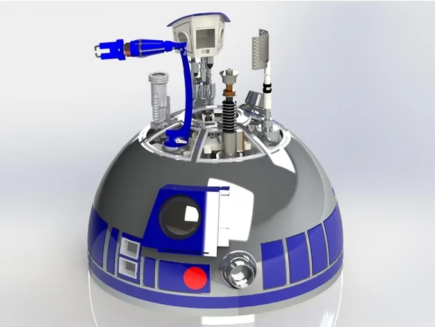
Dome Lift Mechanism R2D2
I am trying to convert a system so it can be used in EZ-B/
The Dome Lift MEchanism by Matthew Zwarts https://www.thingiverse.com/thing:3654411
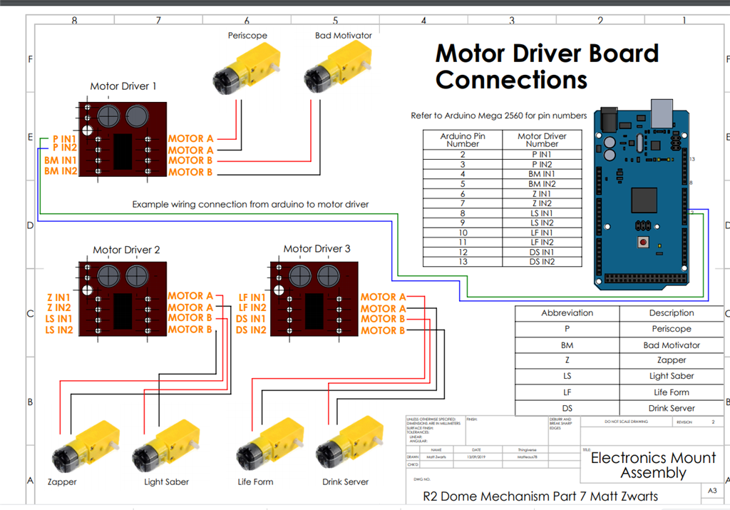
The system works with a hbridge that moves the platform up, hit a switch... Do his thing (depending on which lift, servo movement/leds... than reverse the direction of the platform till it hits the lower switch.
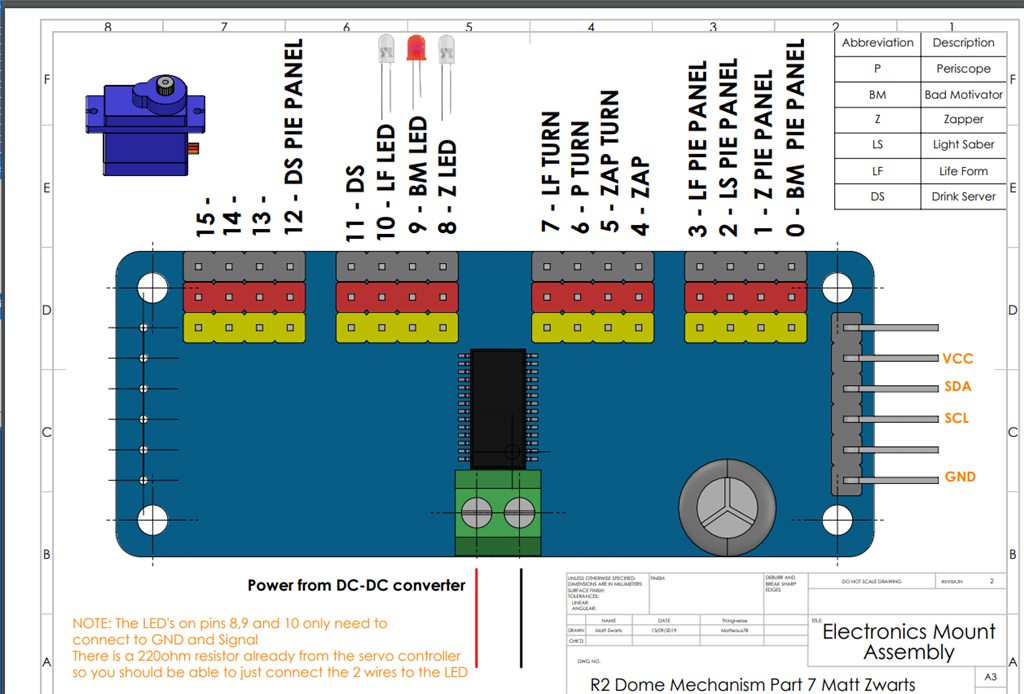
Whil going up ... a panel must be opened first and when going down it should close afterwards...
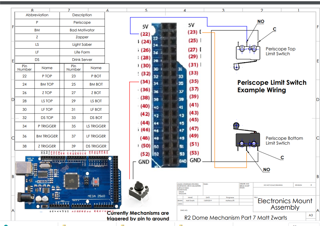
For now the scipt works by pushing a button as trigger.... Link to script: https://www.thingiverse.com/download:7006587
Dome lift in action https://www.youtube.com/watch?v=oZ7mDE0MupM
Example of lift not exact the same used on R2..

The system works with a hbridge that moves the platform up, hit a switch... Do his thing (depending on which lift, servo movement/leds... than reverse the direction of the platform till it hits the lower switch. While going up ... a panel must be opened first and when going down the panel should close afterwards...
Related Hardware (view all EZB hardware)

Related Robot Skill (view all robot skills)

Hi, that’s a very well documented project. It can be done easily with any ezb. I do have a few questions first.
iill start with this question. Is the computer located inside the robot or external?
Wow your always so quick DJ
The mini pc will be in the dome. With some arduinos. Ez-b is in the body.
Okay - that's a great answer because it helps me dial in the suggested solution.
The arduinos can become EZ-B's with firmware. I would recommend using Arduino's connected to the PC via USB. With USB, you don't have to worry about the complications with WiFi interference. It's always concerning when controlling motors by monitoring limit switches via a WiFi connection in case something goes wrong. Specifically in noisy WiFi areas (i.e. conferences)
To move a motor with limit switch, it's quite easy.
load ARC
press Project -> Add Control
Select the SCRIPTING tab and add a SCRIPT control to the workspace. Or to make the project more concise, add SCRIPT COLLECTION instead
Click the Config button on the script
Enter a name for the script, in this example we'll call it "Periscope up"
Select the JAVASCRIPT tab, because that's the code we'll write.
*Notes
Notice the EZ-B index # is specified on the commands. They're optional, but i specified them to demonstrate that you can have multiple ezb controllers connected. So if you have three Arduino EZB controllers connected via USB, they can be all accessed in the code.
The circuit diagram posted does not have a 4.7k pull-up resistor on the limit switch to +3 or +5 (Depending on controller). Do not rely on the internal pull-up on the arduino because it's not strong enough for lengthy wires and switches, etc.. I always use a real 4.7k pull-up resistor on switches with microcontrollers.
Code example to move periscope UP until limit switch is closed
ControlCommand() Now you can call that code from anywhere in your project using the appropriate ControlCommand(). For example, you can add the Speech Recognition control and add the ControlCommand() to execute that script. You can tell the robot to move the periscope that easily. You can also assign that ControlCommand() to a joystick so the buttons will do that. You can also add the ControlCommand() to the camera control so when the robot camera sees different objects, it can move the periscope up.
Other Motors Repeat this process for all of your motors and their limit switches.
Moving Motor Down To have the motors reverse the opposite direction, and use the other limit switch, modify the code. The HBrdige will need the values reversed, and the new limit switch port is needed.
Sounds like a lot, but it's super easy once you perform the first movement
When you're done, there will be a number of scripts for each motor (UP/DOWN). And you can execute those scripts from other controls, such as the speech recognition as seen here...
I did program it all like you explained. I think i have the programming right... Still waiting on jumper wires (i realised i didn't have any stock) so i can test the setup. Still have a question about the setup. Should i make a seperate movement script for opening the panels.... to let the lift go up and activate the servo/lights needed... Or do i put that in the same up/down scripts?
I also tested the minipc with the battery... But the 22.2v 6p lipo 3800mah didn't make it to long... after 3 hours the battery was depleted... So i ordered a Lattepanda... To be less power consuming. (found a cheap deal )
But now i am wondering.... Do i still need the Ez-B 4v2? or can i use that for a later project... And work with arduinos to connect everything to the lattepanda with usb? Connect 1 arduino in the body to control the motors with usb trough a slipring.
)
But now i am wondering.... Do i still need the Ez-B 4v2? or can i use that for a later project... And work with arduinos to connect everything to the lattepanda with usb? Connect 1 arduino in the body to control the motors with usb trough a slipring.
That later project... Maybe a mousedroid... Can that also be controlled with the lattepanda? So 2 droids running on 1 pc?
The latte panda is a good idea with arduinos over usb. That gives you fast immediate response without WiFi interference. Smart idea! Very professional setup
This is an interesting thread for me as I plan to rebuild the sensors on my arm carriage and rail system that moves my Lost In Space B9 robot's arms in and out of his body. Right now I'm using a Sabertooth/Kangaroo to drive an electric window motor that moves the carriage out and in. I have no limit switches and rely on the limit settings I have thought the Kangaroo and an encoder. Because of the slop in my drive train the carriage moving the arm sometimes does not go all the way out to the end of the rail and causes problems. I thought installing limit switches would solve this issue.
I was planning on doing just what the OP wants to do, so I'm reading this thread very closely. I was hoping to keep the Sabertooth but ditch the Roo. I'm not sure I can have the ST stop when hitting a limit switch without the Roo. If not I'll have to ditch that also and get a simple H Bridge. I still need to research this. Maybe I'll have to unload this task to an arduino and finally install a latte panda like I've been wanting to do for years.
I also didn't know there was a concern relying on switches over Wifi. This is good to know. I do also have a quite a few switches and monitor ADC voltages to tell when the're hit.
Wow, Maybe now I'll have to rebuild the entire logic circuit on my robot. I have a very large project for this guy. Perhaps I'll also need to rewrite a lot of my EZ Scripts in Javascript if I can figure out how. I've been using EZ Script for years but no nothing about writing Javascript. From what I've read Javascript is a better way to go. DJ's script examples will really help me get into that language.
Lots to explore and think about. Thanks for the insight!
Hi team,
I am building this lift mechanism for my 3D printed R2D2. The instructions and wiring diagrams are excellent.
Does anyone have experience connecting this mechanism electronics to Padawan360 which (one of) is the control system for the R2D2?
Thanks for any help or advice!
John

Hola , como están estoy trabajando en el sistema de elevación del domo, tengo todos los componentes pero tengo dudas de la conexión de esta tarjeta. agradecería algún diagrama de conexión de este componente para saber como conectarlo correctamente. Saludos desde Chile