Asked
Resolved Resolved by Nink!

Which Way Should I Go For Spot Micro?

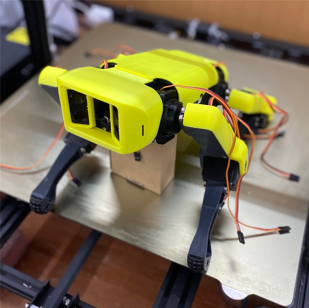
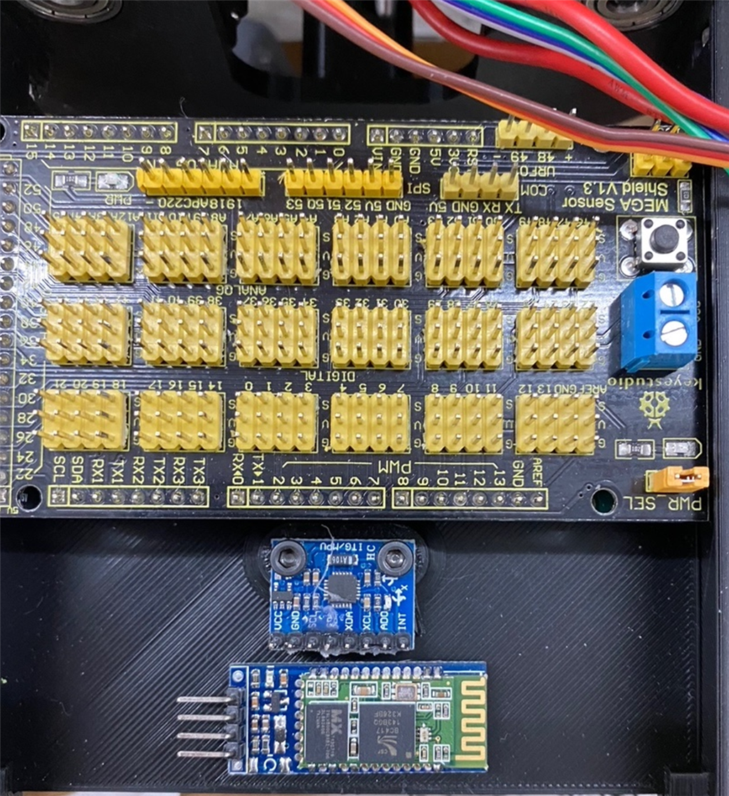
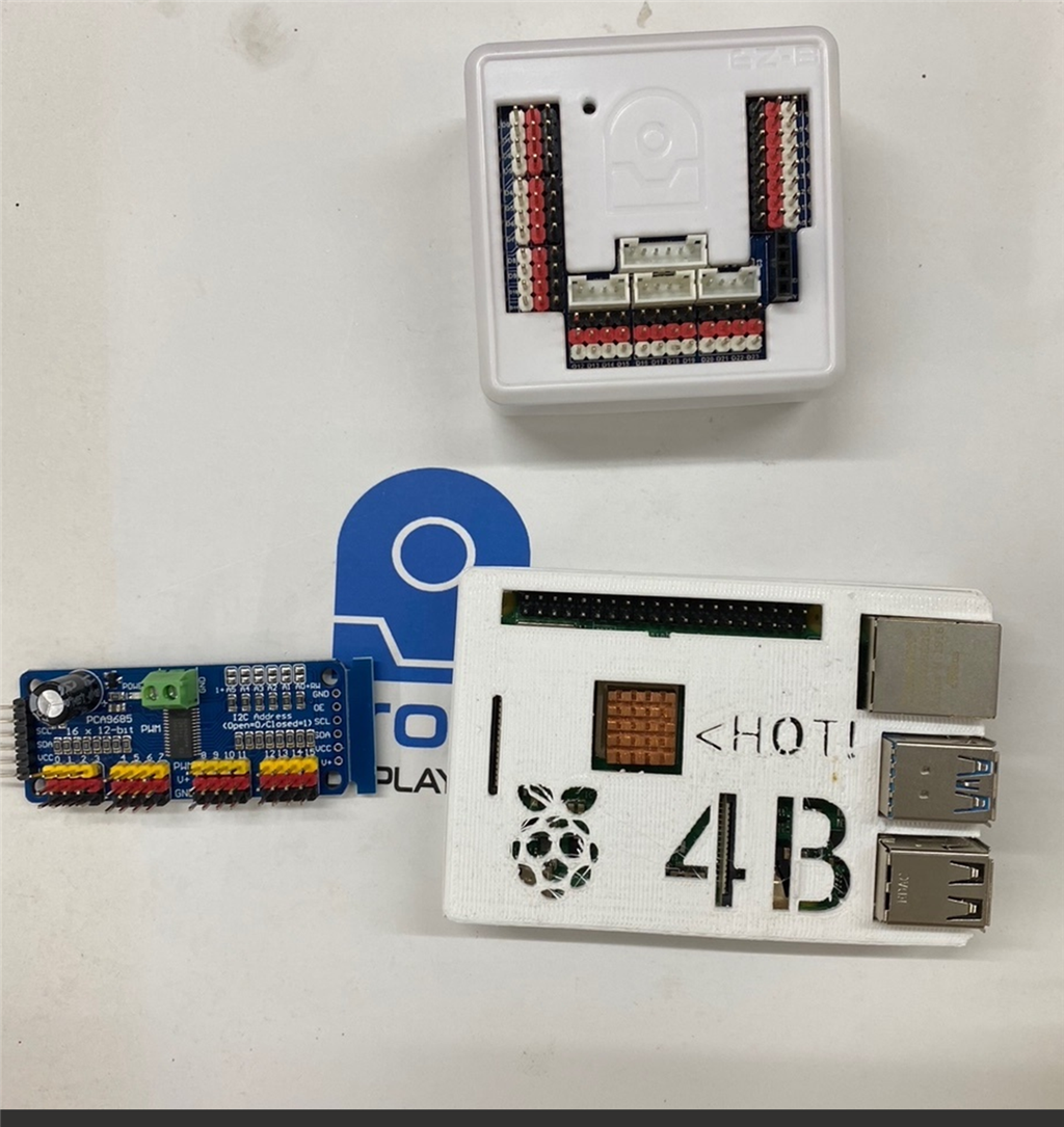
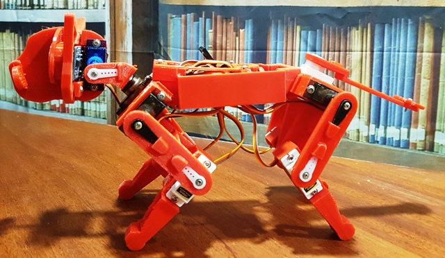
I have completed the mechanical assembly of Spot Micro.    There are several versions for the controlling mechanisms used by various people.  Here is a very cute one that is done with an Arduino Mega as the controller with embedded code in the Arduino.   However, I have other options too such as either using a EZB V4 or a RPI with a servo Module and some reverse kinematics software. 

If I decide to use the EZB V4, this is not that different than the "Six" robot in complexity (maybe).   I have the parts and I am trying to determine which way to go.   The kicker will be designing each step of movement with frames using ARC.  I have not tried anything this complex control-wise.

User-inserted image User-inserted image User-inserted image


Related Hardware Arduino Due/Mega

ARC Pro

Upgrade to ARC Pro

Stay at the forefront of robot programming innovation with ARC Pro, ensuring your robot is always equipped with the latest advancements.

#1   — Edited

Is that little guy big enough to carry an EZB V4? Would an IoTiny fit better and have enough ports? You could also flash that Mega into an EZB.

EDIT: looks liek you need 12 servos. IoTiny only has 8 digital ports. Your mega would do the trick if you flashed it into an EZB.

PRO
Synthiam
#2  

One of the ideas is to use the ardunio with their code and control it from an ezb v4 or iotiny. This allows you to use their existing gait movements without making new ones.

Their arduino code would need a modification if it doesn’t accept serial commands to move directions. But I’m guessing it does. Do you have a link to their arduino source code?

#3  

JD, I like this idea. There are several sources.  I don't know which is best to start with:

https://github.com/lulersoft/spotmicro-controller

https://github.com/MatthiasWM/SpotMicro

I will try to e-mail you the INO file for Max (Spot Micro) I also translated from Dutch.

Most are setup to use a gaming joystick connected via Bluetooth.

PRO
Synthiam
#4  

Looks like the first one is the best to use. It seems to accept serial commands for movements

#5  

Cool.  I think I have another io tiny as well I could use instead of the EZB V4. Thanks for you help DJ!

PRO
Synthiam
#6  

I’ll take a better look at the code and see what the commands are

PRO
Belgium
#7   — Edited

hi all

this guy is making one .maybe is something for you?

#8  

DJ, Did you have a chance to look at the Code to see how I/we can implement the hooks?  Once I get this one done, I would like to offer it up as a spotlight for you.   Any guidance or examples that you can provide would be great.  It seems to me that what I want to do is have the ability to mimic the bluetooth connections and controls via the PS2 joystick via the IOtiny.

Also, I want to be able to read ultra sonic sensor data either from the Arduino/IO tiny.   I would like to eventually integrate a camera too in the nose- that would be direct to the IO tiny.   How do you connect the IO Tiny to the Arduino?

I will build a mobile screen app on top of it all using ARC.

#9   — Edited

DJ, Here is INO file for Max (Spot Micro) that I translated some comments from Dutch to English where needed.   It appears this approach uses 4 analog inputs on the Arduino from a RC Controller receiver Output.  I am wondering if one setup the IO Tiny to output  4 PWM signal outputs if it could simulate the RC receiver outputs and use the same code base in the Arduino Mega.

Spot Robot controller
Jan De Coster
07/01/2021

More info on www.jandecoster.com
This code is part of an online course. Using this code on your robot requires proper knowledge of the platform.
Do not forget to calibrate your robot to avoid catastrophic failure;) 

RC read based on 
Kelvin Nelson's example 24/07/2019
https://create.arduino.cc/projecthub/kelvineyeone/read-pwm-decode-rc-receiver-input-and-apply-fail-safe-6b90eb

*/

#include 

//RC stuff
//RC controller pins
const int CH_0_PIN = A0;
const int CH_1_PIN = A1;
const int CH_2_PIN = A2;
const int CH_3_PIN = A3;
const int deadzone = 20;  //center stick when close to center

int ch_0;
int ch_1;
int ch_2;
int ch_3;
//End RC stuff

//Gyro stuff
#include 
const int MPU = 0x68; // MPU6050 I2C address
float AccX, AccY, AccZ;
float GyroX, GyroY, GyroZ;
float accAngleX, accAngleY, gyroAngleX, gyroAngleY, gyroAngleZ;
float roll, pitch, yaw, oldroll, oldpitch, oldyaw;
float AccErrorX, AccErrorY, GyroErrorX, GyroErrorY, GyroErrorZ;
float elapsedTime, currentTime, previousTime;
int c = 0;

bool safetymode = false;
//End Gyro stuff


Servo servo[12]; //array of servo's

const int servo_pin[12] =  {2, 3, 4, 5, 6, 7, 8, 9, 10, 11, 12, 13};  //arrays of servo pins

const int directions[12] = {1, -1,-1,  1 ,1,1,  -1 ,1,1, -1,-1,-1};  //reflection correction for opposite sides of the robot

const int base[12] = {90 ,100 ,102 ,  90 ,88 ,97 ,  90.00 ,78 ,95 ,  95 ,108 ,100 }; 
//callibration   these are the base values for each servo, that put Spot in a comfortable starting position


/* Servo's can not keep their current position, so we store these in an array angleCurrent
 * The target of each servo is placed in angleTarget, and angleSpeed holds each change in angle for each servo, per function call
 * arcPos holds different poses , with values relative to the base values in array base
 */

float angleCurrent[12] = {base[0], base[1], base[2], base[3], base[4], base[5], base[6], base[7], base[8], base[9], base[10], base[11]}; //real-time arcs
float angleTarget[12] = {base[0], base[1], base[2], base[3], base[4], base[5], base[6], base[7], base[8], base[9], base[10], base[11]}; //expected coordinates of the end of the leg
float angleSpeed[12] = {0.00, 0.00, 0.00, 0.00, 0.00, 0.00, 0.00, 0.00, 0.00, 0.00, 0.00, 0.00}; //each axis' speed, needs to be recalculated before each movement

//step sequence forward
int sb1 = -10;  int so1 = 22;    //sb upperarm  so lowerarm
int sb2 = 2;    int so2 = 1;
int sb3 = -9;   int so3 = 1;      //only for 4 step moves
int sb4 = -21;  int so4 = 19;

//intertia compensation after running
int brb = 1;  int bro = -12;

//brace animation when stopping, to prevent tipping over
int brcb = -14;  int brco = 24;

int pootb = 53;  int pooto = -16;


float arcPos[14][12] = {   //2D array with positions for each servo, adjust initialization as you add steps!
        //Leg Left Front------Leg right Front-----Leg Left rear----Leg Left rear    
        // 0    //base stand
          {0,      0,     0,     0,     0,     0,     0,     0,     0,     0,      0,    0},   
        //shldr   up    down  shldr  up    down     shldr  up    down    shldr  up    down  
           
        // 1    //lay down, safety position when RC is lost
          {0,     0,    45,     0,     0,    45,     0,     0,     45,    0,      0,   45}, 
        //shldr   up    down  shldr  up    down     shldr  up    down    shldr  up    down  
           
        // 2    //stand back , rease back
          {0,     0,    45,     0,     0,    45,     0,      0,     0,    0,      0,     0},
      //shldr   up    down  shldr  up    down     shldr  up    down    shldr  up    down  
          
        // 3    //sit up
          {0,     0,    -15,      0,     0,   -15,     0,      0,    25,    0,      0,   25},
        //shldr   up    down  shldr  up    down     shldr  up    down    shldr  up    down  


        // 4    //step 1   
          {0,    sb1,    so1,     0,   sb2,   so2,   0,    sb1,   so1,    0,    sb2,   so2},
        //shldr   up    down  shldr  up    down     shldr  up    down    shldr  up    down  

        
        // 5    //step 2    
          {0,    sb2,    so2,    0,   sb1,  so1,     0,    sb2,   so2,    0,      sb1,   so1},
        //shldr   up    down  shldr  up    down     shldr  up    down    shldr  up    down  
        
         // 6    //step 3
          {0,    sb3,    so3,    0,   sb1,  so1,    0,    sb3,   so3,    0,    sb1 ,   so1  },
        //shldr   up    down  shldr  up    down     shldr  up    down    shldr  up    down  

         // 7    //step 4
          {0,    sb4,    so4,   0,     sb2,    so2,   0,   sb3,   so3,    0,    sb2,     so2},
        //shldr   up    down  shldr  up    down     shldr  up    down    shldr  up    down  

         // 8    //stand turn
          {0,    0,     0,      0,      0,    0,        0,   0,   0,      0,    0,     0},
        //shldr   up    down  shldr  up    down     shldr  up    down    shldr  up    down  
        
         // 9    //break forward
          {0,    0,     0,      0,      0,    0,        0,   sb1/3,   so1/3,      0,    sb1/3,   so1/3},
        //shldr   up    down  shldr  up    down     shldr  up    down    shldr  up    down  

        // 10    //break backward
          {0,    0,  0,   0,   0,  0,   0,   brb,   bro,      0,    brb,  bro },
        //shldr   up    down  shldr  up    down     shldr  up    down    shldr  up    down  

        // 11    //brace 
          {0,    brcb,  brco,   0,   brcb,  brco,   0,   brcb,   brco,      0,  brcb,  brco},
        //shldr   up    down  shldr  up    down     shldr  up    down    shldr  up    down  
        
          // 12    //sniff 
          {0,    brcb,  brco,   0,   brcb,  brco,   0,   0,   0,      0,  0,  0},
        //shldr   up    down  shldr  up    down     shldr  up    down    shldr  up    down  

         // 13    //raise 
          {0,    0,  0,   0,   0,  0,   0,   brcb,   brco,      0,  brcb,  brco}
        //shldr   up    down  shldr  up    down     shldr  up    down    shldr  up    down  
          };

        
bool to_sit = false; //is Spot sitting down?
bool moving = false; //is Spot moving? then we should wait
bool to_stand = false; //is Spot standing?
bool movingforward = false; //is Spot moving forward?
bool movingbackward = false; //is Spot moving backward?
bool jumped = false; //did Spot jump?
bool sniffing = false; //is Spot sniffing?
bool raised = false; //is Spot looking up?

int angle_of_rotation = 0;  //left right
int tilt_angle = 0;   // up down
int fspeed = 0;     //speed

int currentstep = 1;

void setup() {
  Serial.begin(9600); 

  Wire.begin();                      // Initialize comunication
  Wire.beginTransmission(MPU);       // Start communication with MPU6050 // MPU=0x68
  Wire.write(0x6B);                  // Talk to the register 6B
  Wire.write(0x00);                  // Make reset - place a 0 into the 6B register
  Wire.endTransmission(true);        //end the transmission
  Serial.println("Gyro");
  calculate_IMU_error();
  delay(20);
  
  Serial.println("relay");
  
  //pinMode(1, OUTPUT); //1 when pin available connect this to a relay for extra safety
  //digitalWrite(1, LOW);
  delay(500);
  Serial.println("attach");
  servo_attach();

  setTargets(1,10); //go to lay down, without filling target arrays
  
  //digitalWrite(1, HIGH); //start motors with relay
  delay(1000);
  Serial.println("set");

  
  setTargets(1,10); //go to lay down
  to_sit = true;

  delay(1000);


}

void loop() {

checkRC();  //read RC

readGyro();

if(!safetymode){

angle_of_rotation = ch_0/40;//angle of rotation
fspeed = -ch_1/25;
tilt_angle = ch_3/20; //tilt angle
forwardarray();
turnarray();

  //walking? switch step 1 and 2
  if(abs(ch_1)>40 && !to_sit && currentstep==1){
      if(ch_1>0){
        movingforward = true;
        }else{
          movingbackward = true;
          }
    currentstep = 2;
    setTargets(4,10);
    } 
  else if(abs(ch_1)>40 && !to_sit && currentstep==2){
     if(ch_1>0){
        movingforward = true;
        }else{
           movingbackward = true;
          }
    currentstep = 1;
    setTargets(5,10);
    }
  //not walking ?  
  else{
  
        if(ch_2>0){                 //goes channel 2 above 0?
          if(to_sit){               //Spot sits? standm to_sit is to sit
            mind_lay_down();  
            mind_standup(); 
            to_sit = false;
            }
            else{                     //Spot not sitting? go to stand
              
              to_sit = false;
                 
              if(abs(angle_of_rotation)>2 && !to_sit){
                
                
                setTargets(8,10);
                }else{
                  if(movingforward){
                    setTargets(9,5);
                    movingforward = false;
                    }
                  else if(movingbackward){
                    setTargets(10,5);
                    movingbackward = false;
                    }
                  mind_stand();
                  }
                  
              } 
          }
        
        if(ch_2<-100 && !to_sit){     //goes channel 2 below -100?
          to_sit = true;
          mind_sit();                 // Spot sit
          }
          
        else if(ch_2<-200 && to_sit){      //channel 2 goes below -200?
          mind_lay_down();                 //Spot lay down
          }

        else if(ch_2>220 && !jumped){      //goes channel 2 above 200?
          mind_jump();                 //Spot jump
          jumped = true;
          } 
        else if(ch_2<200){
          jumped = false;
          }  
        if(ch_3>220 && !sniffing && !to_sit){
         mind_sniff();    
         sniffing = true;
          }   
        else if(ch_3<200){
         sniffing = false;
          }
        if(ch_3<-200 && !raised && !to_sit){
         mind_raise();    
         raised = true;
          }   
        else if(ch_3>-180){
         raised = false;
          }      
          
        
    }
}

else if(ch_2<-200){  //leave safety by going to sitting
  to_sit= true;
  safetymode = false;
  
  }
}

void forwardarray(){ //adjust angles according to input
int comp = -angle_of_rotation*0.9;
  
if(fspeed>0){  //
sb1 = -10-abs(fspeed/1.5);  so1 = 22-abs(fspeed/1.5);
sb2 = 2-abs(fspeed/1.5);    so2 = 1-abs(fspeed/1.5);
}else{      //achteruit niet te snel
sb1 = -10-abs(fspeed/3);  so1 = 22-abs(fspeed/3);
sb2 = 2-abs(fspeed/3);    so2 = 1-abs(fspeed/3);
  }

  arcPos[4][1] = sb1-angle_of_rotation;         arcPos[4][2] = so1-angle_of_rotation-comp;                  arcPos[4][4] = sb2+fspeed+angle_of_rotation;  arcPos[4][5] = so2+angle_of_rotation+comp+fspeed/2;   arcPos[4][7] = sb1+angle_of_rotation;          arcPos[4][8] = so1+angle_of_rotation+comp;             arcPos[4][10] = sb2+fspeed-angle_of_rotation; arcPos[4][11] = so2+fspeed/2-angle_of_rotation+comp; 
  arcPos[5][1] = sb2+fspeed-angle_of_rotation;  arcPos[5][2] = so2+fspeed/2-angle_of_rotation-comp;         arcPos[5][4] = sb1+angle_of_rotation;         arcPos[5][5] = so1+angle_of_rotation+comp;            arcPos[5][7] = sb2+fspeed+angle_of_rotation;   arcPos[5][8] = so2+fspeed/2+angle_of_rotation+comp;    arcPos[5][10] = sb1-angle_of_rotation;        arcPos[5][11] = so1-angle_of_rotation+comp; 
}

void turnarray(){  //adjust angles accoridng to input

  int comp = -angle_of_rotation*0.9;

 
  arcPos[4][0] = 0;      arcPos[4][3] = -angle_of_rotation;     arcPos[4][6] = 0;           arcPos[4][9] = angle_of_rotation; 
  arcPos[5][0] = -angle_of_rotation;      arcPos[5][3] = 0;     arcPos[5][6] = angle_of_rotation;   arcPos[5][9] = 0; 
  
  arcPos[8][0] = -angle_of_rotation; 
  arcPos[8][1] = -angle_of_rotation;      
  arcPos[8][2] = -angle_of_rotation-comp;       
  arcPos[8][3] = -angle_of_rotation;
  arcPos[8][4] = angle_of_rotation;       
  arcPos[8][5] = angle_of_rotation+comp;         
  arcPos[8][6] = angle_of_rotation;
  arcPos[8][7] = angle_of_rotation;  
  arcPos[8][8] = angle_of_rotation+comp;          
  arcPos[8][9] = angle_of_rotation;
  arcPos[8][10] = -angle_of_rotation; 
  arcPos[8][11] = -angle_of_rotation-comp;  
  }


void mind_standup(){  //sit up, back first, then front legs
   setTargets(2,5);
   setTargets(0,8);
  }

void mind_lay_down(){   //lay down
  setTargets(1,8);
  }
  
void mind_sit(){ //sit
  setTargets(3,2);
  }

void mind_stand(){ //go to stand not from sitting
   setTargets(0,2);
  }

void mind_kick(){ //go to stand not from sitting
   setTargets(4,15);
   setTargets(5,15);
  }

void mind_jump(){
  setTargets(0,2);
  setTargets(11,4);
  setTargets(0,20);
  }

void mind_sniff(){
  setTargets(12,2);
  }  
  
void mind_raise(){
  setTargets(13,2);
  }  

        
void setTargets(int pos, float myspeed){    // pos = row in array    myspeed = speed from 1 to 20

moving = true;
float delta[12];
float maxDelta = 0;

if(myspeed>20){ myspeed = 20;}
if(myspeed<1){ myspeed = 1;}

for (int i=0; i < 12; i++){
 
  angleTarget[i] = base[i]+arcPos[pos][i]*directions[i];
  delta[i] = base[i]+arcPos[pos][i]*directions[i] - angleCurrent[i]; 
  
  if(abs(delta[i])>maxDelta){
    maxDelta = abs(delta[i]);
    }
  
  if(delta[i]>0){
    angleSpeed[i] = myspeed;
    }  
  else if(delta[i]<0){
    angleSpeed[i] = -myspeed;
    } 
  else{
      angleSpeed[i] = 0;
      }  
 
  } 
 
  while(moving){  //repeat function while servo's not at destination
    setServos();
    delay(5); //give it some time
    }
 
}

void setServos(){
  
  int speedcount = 0; //count all servo's that are still moving

  //for each servo, what is the distance between current angle and target angle
  //smaller then 1? make current angle target angle en put speed to 0
  //if not, add speed to current angle with factor 1/10 adjusted with speed

  
  for (int i=0; i < 12; i++){
    if(abs(angleTarget[i]-angleCurrent[i])<=1){
        angleCurrent[i] = angleTarget[i];
        angleSpeed[i] = 0;
        }else{
         angleCurrent[i] += angleSpeed[i]/10; 
          }
  
    servo[i].write(constrain(angleCurrent[i],10,170));  //angles are put in the array, now put the servo at right position
  }

  //are servo's still moving?
  for (int i=0; i < 12; i++){
    speedcount += abs(angleSpeed[i]);
    }
  //if not  (speedcount = 0) stop moving, while loop stops
  if(speedcount==0){
    moving = false;
    }  
    
}


void servo_attach(void){  
  for (int i = 0; i < 12; i++)
  {
    servo[i].attach(servo_pin[i]);
    
    delay(100);
  }
}


void checkRC(){ //convert RC pulses to variables
   // Read pulse width from receiver
  ch_0 = pulseIn(CH_0_PIN, HIGH, 25000);
  ch_1 = pulseIn(CH_1_PIN, HIGH, 25000);
  ch_2 = pulseIn(CH_2_PIN, HIGH, 25000);
  ch_3 = pulseIn(CH_3_PIN, HIGH, 25000);

  ch_0 = pulseToPWM(ch_0);
  ch_1 = pulseToPWM(ch_1);
  ch_2 = pulseToPWM(ch_2);
  ch_3 = pulseToPWM(ch_3);
  

  }


// Convert RC pulse value to motor PWM value
int pulseToPWM(int pulse) {
  
  // pulses between 1000 and 2000 converted to -255 and 255
  
  if ( pulse > 1000 ) {
    pulse = map(pulse, 1000, 2000, -500, 500);
    pulse = constrain(pulse, -255, 255);
  } else {
    pulse = 0;
  }

  // Anything in deadzone should stop the motor
  if ( abs(pulse) <= deadzone ) {
    pulse = 0;
  }

  return pulse;
}


void readAcc(){
  // === Read acceleromter data === //
  Wire.beginTransmission(MPU);
  Wire.write(0x3B); // Start with register 0x3B (ACCEL_XOUT_H)
  Wire.endTransmission(false);
  Wire.requestFrom(MPU, 6, true); // Read 6 registers total, each axis value is stored in 2 registers
  //For a range of +-2g, we need to divide the raw values by 16384, according to the datasheet
  AccX = (Wire.read() << 8 | Wire.read()) / 16384.0; // X-axis value
  AccY = (Wire.read() << 8 | Wire.read()) / 16384.0; // Y-axis value
  AccZ = (Wire.read() << 8 | Wire.read()) / 16384.0; // Z-axis value
  // Calculating Roll and Pitch from the accelerometer data
  accAngleX = (atan(AccY / sqrt(pow(AccX, 2) + pow(AccZ, 2))) * 180 / PI) - 0.58; // AccErrorX ~(0.58) See the calculate_IMU_error()custom function for more details
  accAngleY = (atan(-1 * AccX / sqrt(pow(AccY, 2) + pow(AccZ, 2))) * 180 / PI) + 1.58; // AccErrorY ~(-1.58)
  
  }
  
void readGyro(){
// === Read gyroscope data === //
  previousTime = currentTime;        // Previous time is stored before the actual time read
  currentTime = millis();            // Current time actual time read
  elapsedTime = (currentTime - previousTime) / 1000; // Divide by 1000 to get seconds
  Wire.beginTransmission(MPU);
  Wire.write(0x43); // Gyro data first register address 0x43
  Wire.endTransmission(false);
  Wire.requestFrom(MPU, 6, true); // Read 4 registers total, each axis value is stored in 2 registers
  GyroX = (Wire.read() << 8 | Wire.read()) / 131.0; // For a 250deg/s range we have to divide first the raw value by 131.0, according to the datasheet
  GyroY = (Wire.read() << 8 | Wire.read()) / 131.0;
  GyroZ = (Wire.read() << 8 | Wire.read()) / 131.0;
  // Correct the outputs with the calculated error values
  GyroX = GyroX + 0.56; // GyroErrorX ~(-0.56)
  GyroY = GyroY - 2; // GyroErrorY ~(2)
  GyroZ = GyroZ + 0.79; // GyroErrorZ ~ (-0.8)

  // Currently the raw values are in degrees per seconds, deg/s, so we need to multiply by sendonds (s) to get the angle in degrees
  gyroAngleX = gyroAngleX + GyroX * elapsedTime; // deg/s * s = deg
  gyroAngleY = gyroAngleY + GyroY * elapsedTime;
  yaw =  yaw + GyroZ * elapsedTime;

  // Complementary filter - combine acceleromter and gyro angle values
  roll = 0.96 * gyroAngleX + 0.04 * accAngleX;
  pitch = 0.96 * gyroAngleY + 0.04 * accAngleY;
  
//  // Print the values on the serial monitor
//  Serial.print(roll);
//  Serial.print("/");
//  Serial.print(pitch);
//  Serial.print("/");
//  Serial.println(yaw);

    if(abs(GyroX)>200){
      Serial.println(GyroX);
      safetymode = true;
      setTargets(1,5);
      
      }
  if(abs(GyroY)>200){
      Serial.println(GyroY);
      safetymode = true;
      setTargets(1,5);
      }
    if(abs(GyroZ)>200){
      Serial.println(GyroZ);
      safetymode = true;
      setTargets(1,5);
      }  
}

void calculate_IMU_error() {
  // We can call this funtion in the setup section to calculate the accelerometer and gyro data error. From here we will get the error values used in the above equations printed on the Serial Monitor.
  // Note that we should place the IMU flat in order to get the proper values, so that we then can the correct values
  // Read accelerometer values 200 times
  while (c < 200) {
    Wire.beginTransmission(MPU);
    Wire.write(0x3B);
    Wire.endTransmission(false);
    Wire.requestFrom(MPU, 6, true);
    AccX = (Wire.read() << 8 | Wire.read()) / 16384.0 ;
    AccY = (Wire.read() << 8 | Wire.read()) / 16384.0 ;
    AccZ = (Wire.read() << 8 | Wire.read()) / 16384.0 ;
    // Sum all readings
    AccErrorX = AccErrorX + ((atan((AccY) / sqrt(pow((AccX), 2) + pow((AccZ), 2))) * 180 / PI));
    AccErrorY = AccErrorY + ((atan(-1 * (AccX) / sqrt(pow((AccY), 2) + pow((AccZ), 2))) * 180 / PI));
    c++;
  }
  //Divide the sum by 200 to get the error value
  AccErrorX = AccErrorX / 200;
  AccErrorY = AccErrorY / 200;
  c = 0;
  // Read gyro values 200 times
  while (c < 200) {
    Wire.beginTransmission(MPU);
    Wire.write(0x43);
    Wire.endTransmission(false);
    Wire.requestFrom(MPU, 6, true);
    GyroX = Wire.read() << 8 | Wire.read();
    GyroY = Wire.read() << 8 | Wire.read();
    GyroZ = Wire.read() << 8 | Wire.read();
    // Sum all readings
    GyroErrorX = GyroErrorX + (GyroX / 131.0);
    GyroErrorY = GyroErrorY + (GyroY / 131.0);
    GyroErrorZ = GyroErrorZ + (GyroZ / 131.0);
    c++;
  }
  //Divide the sum by 200 to get the error value
  GyroErrorX = GyroErrorX / 200;
  GyroErrorY = GyroErrorY / 200;
  GyroErrorZ = GyroErrorZ / 200;
  // Print the error values on the Serial Monitor
  Serial.print("AccErrorX: ");
  Serial.println(AccErrorX);
  Serial.print("AccErrorY: ");
  Serial.println(AccErrorY);
  Serial.print("GyroErrorX: ");
  Serial.println(GyroErrorX);
  Serial.print("GyroErrorY: ");
  Serial.println(GyroErrorY);
  Serial.print("GyroErrorZ: ");
  Serial.println(GyroErrorZ);
}
PRO
Synthiam
#10  

Looking at the code, your pwm idea would work fine. The ideal solution in the long term would be to modify that code for digital commands. But the pwm will work to get you up and running.

The code is pretty messy. Lots of spaghetti IF conditions that could have been grouped together. So modifying that kind of piecemeal code is difficult lol

PRO
Canada
#11  

EZB 4V is pretty compact when you take it out of the case you just need to solder power connector on it.  I use them in a couple of robots this way.

#12  

DJ, I have wired an IO Tiny D0, D1,D2, and D3 to  the Arduino A0,A1,A2, and A3 in each case - ground to ground, voltage to voltage and signal to signal on each channel This is a very rudimentary question.  I have been trying to send a PWM signal from the IO Tiny to the Arduino on each channel to mimic the RC radio receiver output.  Can  you give me an example code snippet of how you would do it?   I am not sure I know what I am doing.

Nink/DJ, I am seriously thinking about that next - booting the Arduino mega and just take my EZB V4 and use it.  I would have to start all over with teaching the robot the walking gates - but that could be fun in the end.

I have included a photo of my attempt...User-inserted image

PRO
Canada
#13  

looks great.

Here is the code from my 19 DOF biped I used to make it walk.

no code

oh yeah there isn’t any code because I used an EZB and a movement panel.

:)

#14  

Nink, Is your project code posted public ally on the cloud drive?

PRO
Synthiam
#15  

Make sure you have a GND connected between the two

You send PWM with the pwm command (i'm guessing you are using ezscript): https://synthiam.com/Support/ez-script-api/ezscript


PWM (digitalPort, speed)

         Set the PWM (Pulse Width Modulation) to the desired duty percentage cycle

         This simulates voltage on the specified pin (Between 0 and 5v)

         PWM Value is between 0 and 100

         Example: PWM(D14, 90)

#16  

DJ, I tried that.  But the arduino code must have been misbehaving.  Anyway, I booted the whole approach and moved right over the the EZBV4! Got the servo profiles setup and spot on his feet.

What tutorial do you recommend for using the frame approach for the servo motions? User-inserted image User-inserted image User-inserted image User-inserted image

PRO
Synthiam
#18  

Looking at the code, all of the positions you need are in there. The value of 0 in their code would be 90 in arc. Because they use - negative values for one way and positive for the other

PRO
Synthiam
#19  

That arduino code also has an IMU connected. Do you have one on the i2c port? Maybe that's why it isn't working for you. I'm guessing they use it for helping balance and such. Probably a good idea to use their code and control it via pwm from the iotiny if you can. That way you can build off the work they've already done rather than reinventing it.

PRO
USA
#20   — Edited

mstephens 42

I was looking at nallycat model, it inspired me.

User-inserted image

Here is walking dog

#21  

I was wondering if this project is still active. I am considering making something like this.

#22  

Please see my other comment in this in the other thread. If you are looking on ways to program this or your other quad, you may want to look here. Might find something with some research.

https://hackaday.io/list/29475-walkers

#23  

Happy New Year Perry. Thanks for the info. I will check it out. It looks like a lot info is available

Canada
#24  

Nice work! One of the teams at my club, AC Robotics is also making a mini 'Spot' called Canis.

PRO
Canada
#25  

It was a nice hot day in Toronto yesterday so I had a few beers on the deck.

woke up this morning and I found this on my work bench. A couple of JD’s had been sacrificed to the robot gods.

I guess I can clean it up and throw some code down.

Let’s call it JDog. User-inserted image

PRO
Synthiam
#26  

Hahaha oh my - those must have been good beers. I spit out my milk and laughed at that thing. Bet it walks great and is very stable. Just kinda caught me off guard