
PRO
rz90208
USA
Asked
Using Arduino Mega As A Isolation Device
Looking for an inexpensive way to isolate the EZBv4 signal line from the Hitech 805bb servos on my inMoov. I am think of using 2 Ardunio megas as isolation devices. Connecting the EZB servo ports to pins 0 - 24 of the Arduino and the servos to pins 30 - 54 of the Arduino and using the following code (just a quick sketch)
void setup() {
  for (int i=0;i<25;i++)
  {

    pinMode(i,INPUT);
    pinMode(i+30,OUTPUT);
  }

}

void loop() {
  int val = 0;
  for (int i=0;i<25;i++)
  {
    val = digitalRead(i);
    digitalWrite(i+30,val);
  }

}
I have not tried it yet, thought I would bounce it off the community first.
Your thoughts?
RichardZ
Related Hardware (view all EZB hardware)
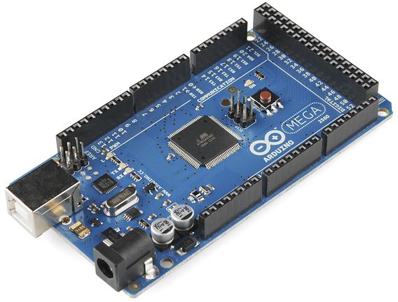
Arduino Due/Mega
by Arduino
Synthiam ARC enables Arduino Mega 2560 control with 8 ADC, 13 PWM, 21 digital ports and 24 servos; includes firmware, shield and tutorials
USB
Servos
24
Camera
Audio
UART
3
I2C
ADC
8
Digital
21
Related Robot Skills (view all robot skills)

EZB Connection
by Synthiam
Connects EZ-B I/O controllers to ARC via COM or IP (5 connections). Supports init scripts, battery monitoring, TCP/EZ-Script server and serial/I2C.

EZ-B V4 Info
by Synthiam
Displays EZ-B v4 internal temperature and battery voltage, shows built-in battery monitor and LiPo protection settings in Connection Control.

Mind if I ask why you want to isolate the signal line? Most of us inmoov people simply isolate the servo power buss and leave the signal connected to the EZ controller along with a ground.
I have had a 805BB cook and take out the lower EZBv4 ports. Not realizing at first it was the servo, I tried swapping EZB's and took out the lower ports on the other EZB. I have replaced the servo and the boards in both EZBv4s but am now a bit gun shy and want to prevent this from happening again.
ahh, luckily I have not had the same problems with mine. Perhaps others will chime in and help with your Arduino question. Good luck
I have also been considering using 6 - 74LS244 but 2 Arduino Megas I think would be cleaner. And a lot less time and work.
I haven't really tried them myself but have you thought of using opto-isolators? It looks like there are a few breakout boards on the market.
Opto-isolators are also designed not blow as often as Buffer chips/Arduino go-between boards.
I have never heard from other InMoov builders having this issue or had this problem with my InMoov which causes the 805b servos to take out the ports on the EZB controller?
Are you powering the servos via a separate PSU/Battery or only one supply for both servos and EZB’s?
If you use a Arduino to isolate the signal between the EZB and servos, wouldn’t this then just blow the port/s on the Arduino, if this is really the problem??
While that code is an interesting approach, it’s going to twitch and burn out the servos quickly due to the twitching. The reason is there’s an analog pwm from the ezb being interpreted by the arduino and then creating a second pwm for the servos. That’ll be very noisy
also, the arduino servo library isn’t to be trusted. If you take a look on the oscilloscope, the way the pwm is generated is kinda hacked and it moves around quite a bit. It’s okay, but I’m not a fan of the pwm is generates. Also, I don’t know if all the ports you wish to use can be servo or pwm read on the arduino.
if you wanted to have another controller responsible for the servos, id recommend connecting the arduino via uart to the ezb and using virtual servos so there’s no analog interpretation. This would be similar to how the scc-32 works.
@Jeremie My first thought was to use opto-couplers but the Arduino solution just seemed so much easier and I have a drawer full of 74LS244's from my TRS-80 days. Showing my age now!
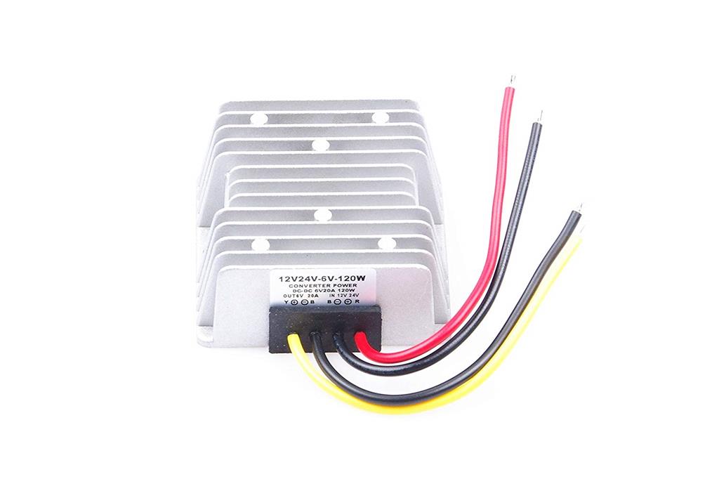
@CEM I am using a Switching power supply out of a large Dell Server. I run the 12v output through 2 12v to 6v DC to DC converts. The 6v powers the EZBs and the Servos NOT through the EZBs.
@DJ I knew you would have some insight on this. It just seemed to easy as I have plenty Arduinos Megas on the shelf.
Maybe I am making to much of this. Since no one else is having this issue, just consider it a fluke and wire him back up and move on.