Welcome to Synthiam!

The easiest way to program the most powerful robots. Use technologies by leading industry experts. ARC is a free-to-use robot programming software that makes servo automation, computer vision, autonomous navigation, and artificial intelligence easy.

Get Started
Asked — Edited

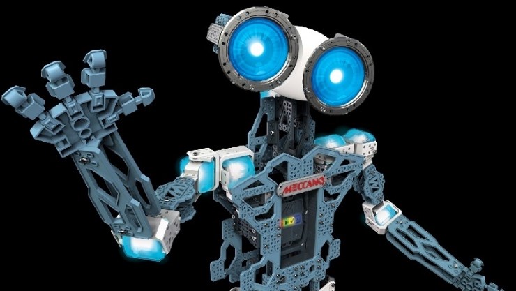
Spinmaster Meccanoid Robot

Anybody seen this guy yet.Looks interesting.He is shown on Youtube 2015 CES show.
User-inserted image


ARC Pro

Upgrade to ARC Pro

Unleash your creativity with the power of easy robot programming using Synthiam ARC Pro

AI Support Bot
Related Content
Synthiam
Based on your post activity, we found some content that may be interesting to you. Explore these other tutorials and community conversations.
PRO
Synthiam
#41  
It would be good for that product to see Spin master to acknowledge the amazing potential the ezb provides before meccanoid becomes the next vaporware. Adding arduino is a backward approach to the usability their platform is meant for. Arduino doesn't open educational options, or expand their market.
Switzerland
#42  
Hi,
just got one as well, from a neighbour who was bored with the functionality.
tried to translate supplied C# library into EZB scripting ........... but no success. it seems they use 2400baud " start bit - 417us LOW" which I can not set in EZB........
how can I get it working with EZB v4 without using SDK or changing servos?
PRO
Synthiam
#43  
Use the SendSerial() command and select 2400 baud as your baud rate.

Otherwise use the UART commands and set the baud rate to 2400 if you wish to use one of the three hardware uarts on the ezb
Switzerland
#44  
how do I add startbit + stopbit?
{LOW, Bit 0, Bit 1, Bit 2, Bit 3, Bit 4, Bit 5, Bit 6, Bit 7, HIGH, HIGH}
Switzerland
#45  
void MeccaBrain :: sendByte(byte servoData){
pinMode(_pmwPin, OUTPUT);

digitalWrite(_pmwPin,LOW);
delayMicroseconds(bitDelay); // start bit - 417us LOW

for (byte mask = 00000001; mask>0; mask <<= 1) { // iterate through bit mask
if (servoData & mask){ // if bitwise AND resolves to true

digitalWrite(_pmwPin,HIGH); // send 1

}else{ // if bitwise and resolves to false

digitalWrite(_pmwPin,LOW); // send 0
}
delayMicroseconds(bitDelay); //delay
}

digitalWrite(_pmwPin,HIGH);
delayMicroseconds(bitDelay); // stop bit - 417us HIGH

digitalWrite(_pmwPin,HIGH);
delayMicroseconds(bitDelay); // stop bit - 417us HIGH
PRO
Synthiam
#46  
If they are using a start bit and 2 stop bits, then you're correct that the ezb will not communicate with their silly use of uart. A suggestion would be to throw an arduino between the two.

Have the arduino take the standard ez-b uart transmission and convert it to the start and 2 stop bits of of the meccanoid.

Or, if you know the commands for the meccanoid... simply create an arduino sketch that transmits the comands to the meccanoid based on input from the ez-b. Publish the meccanoid protocol here and i'll give you a hand.
Switzerland
#47  
have uploaded an EZB project (public, Meccanoid3) which is able to move 1 MeccaNoid servo.

in same EZB project is a script wich contains an arduino sketch that can move all MeccaNoid servos.

and here the lib for arduino:

meccanoid-library.zip
Singapore
#49  
Thanks DJ! This is awesome. I've been holding off doing servo conversion of the meccanoid as my Daughter likes some of the simple features of the original 'meccabrain' (horrible name and just as bad design) such as motion capture and real time recording/playback of movements. I now plan on having the EZ-B and meccabrain switchable so the thing can please us both:)

I'm a little confused on the last part of the tutorial though. For the feet, do I just need the motor controller (it says it comes with leads for ez-b connection) that is listed in the diy products page, or will I need to perform the really really scary steps detailed in the video on the hbridge controller page (http://www.ez-robot.com/Tutorials/Help.aspx?id=70) which includes chopping pins off and soldering bridges etc?
PRO
Synthiam
#50  
No soldering:)

The included wires replace the need to solder
Switzerland
#51  
Hi DJ, thanks a lot:-)

the resistors are used as part of the "smart?" communication feedback:

***********************
The bits of Smart Module data bytes are about 1.1ms long. Each byte has a start bit that is ~2ms LOW. There is no stop bit.
Unlike the bits from the MeccaBrain which are just HIGH and LOW for 1 and 0, the bits from the Smart Modules are based on high pulse widths. A 1 bit is when a High pulse is > 400ms; a 0 bit is when the High pulse is < 400ms.
**************************
as long as we just send, it seems to work without resistors as well

User-inserted image
PRO
Synthiam
#52  
That helps! So it's two start bits.

The pull up is still a little unusual, as the mcu should rest high anyway. I'll update the tutorial with this info
Singapore
#53  
Hi @DJSures,

Thanks again for the tutorial on using the EZ-B to control the standard meccanoid servo's. It's taken me a while to get to it, but I now have all head and arm servo's working, and am able to change the servo color of each using the supplied instructions.

One thing I'm not clear of however, is how to control the meccanoid RGB eye color. These are a different format to the LED color commands.

In the arduino sketch supplied with the tutorial, the LED eyes are specified as being in servo position 2.2

Quote:

//Chain 1 - Left Arm. 1.0 is Arm Pitch, 1.1 is Arm Roll, 1.2 is Elbow
//Chain 2 - Head. 2.0 is Head Yaw, 2.1 is Head Roll, 2.2 is LEDs
//Chain 3 - Right Arm. 3.0 is Arm Pitch, 3.1 is Arm Roll 3.2 is Elbow


but the constant bytes defined underneath them skip the LED's entirely.

Code:


const byte LEFT_ARM_PITCH = 0;
const byte LEFT_ARM_ROLL = 1;
const byte LEFT_ARM_ELBOW = 2;
const byte HEAD_YAW = 3;
const byte HEAD_ROLL = 4;
const byte RIGHT_ARM_PITCH = 5;
const byte RIGHT_ARM_ROLL = 6;
const byte RIGHT_ARM_ELBOW = 7;


Furthermore, the setting of the eye color is different to the servo led's as defined in the sketch:-

For the servo LED's:

Code:


// set the servo color
// for example, setJointColor(RIGHT_ARM_ELBOW, JOINT_VIOLET)
void setJointColor(byte jointName, byte color)


aligns nicely with your example, but the eyes have RGB LED's which are set differently:

Code:


//Set the color of eye LEDS. red, green and blue are from 0 to 7 (0 - no color, 7 - max color).
//fadetime is from 0 to 7 and means the speed of color change (0 - immediate change, 7 - longest change)
//example: setColor(7,0,0,3) means change color to red with average speed
void setEyesColor(byte red, byte green, byte blue, byte fadetime)


Consequently I'm unsure how to send a command from the EZ-B to the RGB eyes to set their color. Would I need to do something like:

Code:


UARTInit(0, 0, 9600)

definearray($mecaSend, 5)

$mecaSend[0] = 0x02 # set RGB Eye Color
$mecaSend[1] = 0x00 # Value for R
$mecaSend[2] = 0x00 # Value for G
$mecaSend[3] = 0x00 # Value for B
$mecaSend[4] = 0x09 # Fadetime

UARTWriteBinary(0, 0, $mecaSend)


having defined 0x02 somewhere in the arduino sketch?

Any advice would be appreciated. Thanks.
Singapore
#54  
From looking at some if the forum posts around UART, it appears to me that you can use them for regular serial communication as well as bit-wise operations, is that correct?

I saw one example (but can't seem to find it again) where I saw something like

Code:

 UartWriteBinary(0,0,"Hello World") 
but I'm clearly clueless with Uart comms *stress* so would appreciate some assistance. The tutorial addresses everything else (servo's, servo led's, feet motors), but makes no mention of The Eye RGB led's.
Switzerland
#55  
Hi Aceboss,
open the example files in the cloud and search for "Meccano MeccaNoid"
it is an incomplete project, but has the eye colour change in (without fading)
Singapore
#56  
Thank you Jetpilot, that helped put me on the right track.

There's a couple of bits of your logic I don't quite understand (for instance the use of shift byte right) in your ez-script, however I've managed to get the eyes working with fade by sending 5 bytes (the 5th being a fade duration).

For some reason it doesn't work if I only do a UARTWriteBinary once, but if I loop the sending section then it works.

Also not sure why the switch case in the arduino script won't trigger if I add a case 2: but does if I use an if (cmd ==2) statement, but since that's arduino code specific probably not relevant in this thread.

Anyhow, maybe not the optimum solution but it's working now:) Thanks for your help.
PRO
Canada
#57  
I made a quick cable and connected an arduino to my Meccanoid servo's using tutorial and then connected EZB to arduino via UART. I wrote a quick script from samples and worked very well (THANKS FOR WRITING THIS UP).

Has anyone written a script to read current server position. (Disable Servo, Manually move, read servo position).

Thanks.
#58  

Quote:

Has anyone written a script to read current server position. (Disable Servo, Manually move, read servo position).

@Nink Hobby servos like EZ Robot HDD type (as opposed to Dynamixel type) have no ability for feedback... aka position feedback... However you can hack a hobby servos to read the servos internal potentiometer by soldering a 4th wire to the wiper pin of the internal pot... You connect that wire to the ezb4's analog port which will give a relative servo position...
PRO
Canada
#59  
Hi @Richard_R The Meccanoid Servo's may be junk and no torque but they did one thing right, they have a potentiometer in them so they have the ability to report servo position. You can put the meccanoid in LIM mode and then record a series of movents by manually moving arms head etc. Meccanoid records the movements and plays them back. The Arduino Firmware appears to support it if you read the meccabrain.cpp file but the sample code on the arduino that interfaces with the EZB does not appear to support it.
PRO
Canada
#60  
The existing code did not support reading servo positions. It appears to be supported in the official BIOS but was not intuitive or clearly documented. I decided to use meccontrols BIOS and wrote a script to do the following with meccanoid servo's, an Arduino and EZB V4
1) Reset all servo's and Set 2 Servo's red and 2 Servo's green
2) If you move a red servo by hand the green servo mirrors the red servo position

This is my first ez-robot script so code is spaghetti. Error correction on reading data from the UART is complex as the data size changes dependent on if the servo is at 99 degrees or 100 degrees. There is no Start Code only end code (CR/LF) in packet. Each number for servo location is sent by the BIOS as its ASCII equivalent for the actual number. So 120 degrees is sent as 5 separate numbers to represent 1,2,0 and CR LF. You receive the servo position in 5 fields 49 50 48 13 10 (No idea why the BIOS does this). Writing to the bios is done in a string so you have to get 3 separate numbers convert each to ASCII and then reassemble them back into a string to write back to the BIOS software. Because the meccontrol firmware writes in single string but reads in 4 to 5 numeric fields of ASCII code there is lots of messy converting back and forth.

I need to clean up and create subroutines so you can have more servo without duplicating code. It is very slow as it can only read or write one servo at a time. I need to be able to read multiple servo positions at 1 time and write new positions at 1 time. I am not sure yet how to approach this, I may have to fork the BIOS. If someone who knows EZ-Script can clean up I would appreciate it.

http://www.ez-robot.com/Community/EZCloud/RobotAppDetails.aspx?id=5184


User-inserted image