
Darathian
USA
Asked
— Edited
Spec Sheet
This thread synthiam.com/Community/Questions/4570 made me wonder if there is a spec sheet showing min/max voltages, current (per pin as well as overall for the board) etc on the new EZ-B pins / power inputs.
Thanks

The answer is the amount of current you apply to it is what you get per pin. If you're asking about the current sink per pin on the microcontroller, that's the same as all other microcontrollers - as they're all about the same.
From that thread, I wrote:
I could have been clearer. I was referring to current sink.
Thanks DJ
Roger that. The answer is 25mha (same as almost all microcontrollers). The datasheet is here: CD00237391.pdf ... It's a long read!
Again, excuse me for being slightly daft here... So you're saying the power pin on the digital ports will equal whatever power you are supplying to the board.... I get that part... But here in the specs page of the EZB4 it says ".24 x 5 volt tolerant Digital ports (servos, PWM, and more)".... So if the former is now true (pin voltage = input voltage), how would we drive typical devices like pings that use only 5V? Would we have to power the board with a limit of 5V in this case?
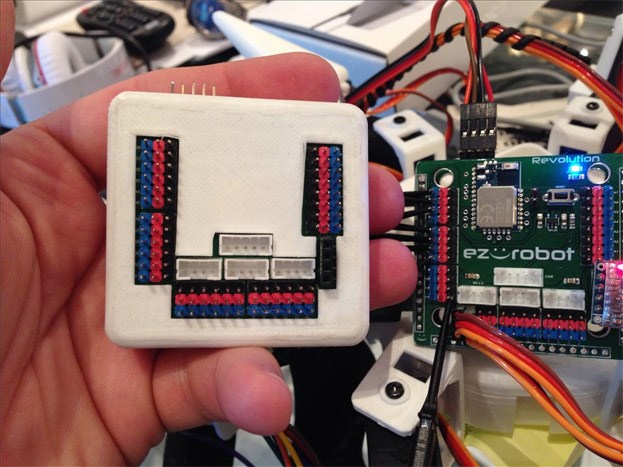
We have a module which will be put on the website within the next week. It looks like a 3 pin connector, but has a 5 volt regulator built in.
The trouble with putting a voltage regulator for all pins on the board is heat and limited current draw. For example, if you ran more than 5 servos the EZ-B v3 would get very hot. If you wanted to run heavy duty servos, you would need an additional power source.
Our new servos used for the Lever HDD Servo-motor and Rotation HDD Servo-motor use the HDD Servo. That servo is tolerant for 7.4 volts input - so it'll power right off the EZ-B from a LiPo Robot Battery 7.4v 1300mAh
The 5 volt tolerant means the digital pin can accept 5 volts of input. This is special to the choice of ARM processor we selected. All other ARM processors are only 3.3v - which would be practically impossible to use with any sensors, etc..
For people using a lot of servos in their projects that makes sense... I use a lot of 5v peripherals so I hope you guys will allow me to add a couple of your 5V modules to one of my orders then...
Cheers
So wait... All the servo/digital ports shown here have a voltage dependant on your battery? hmmmm. Well, I don't think it will effect my roli project. Oh wait. I have a mini servo!...... What's the max voltage the mini servo in the shop?
Yes.
If 7.4v is a problem you can always fit a regulator before the EZ-B and supply the EZ-B with whatever voltage you require however current will be limited by the regulator. Parallel multiple regulators and you can increase the max current available though... I.e. put 10 x 5v 1A regulators in parallel and you have 5v 10A to play with on the EZ-B's digital pins (provided 5v is enough to power the EZ-B).
Or, you can fit regulators in the Vcc of the digital ports. The VCC powering the servos can all be taken from the same port if required so if you have 2 or 3 micro servos that require 5v you could take signal from D0-D2, take the vcc and ground of D0 through a 5v regulator then feed the three servos with the same regulated Vcc and common ground.