
Asked
— Edited
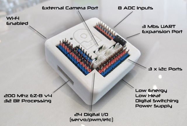
Pin Out Details On Ezb V4
On the EZB V4 digital pins, what color is VCC Pin, Output/Input pin, and Gnd Pin? Is it White(or Blue), Red, Black?
On the EZB V4 digital pins, what color is VCC Pin, Output/Input pin, and Gnd Pin? Is it White(or Blue), Red, Black?

Black is ground. Red is VCC, White is signal (i/o). (note, that photo is of a prototype board where the signal pins are blue, and there is an extra set of signal pins along the left side header row that do not exist on the production EZ-B's).
Alan
Red vcc, black ground white is signal. Blue is replaced with white.
I am trying to get the HC-SR04 to work, but having issues. I did 3d print some parts and it looks great.
Here is what I have tried: HC-SR04. Digital pins Gnd----------------D20, black pin ECHO--------------D20, white pin TRIG ---------------D21, white pin VCC ----------------D21, red pin
Set up in ping distance control.
Not getting anything but 255 from sensor. Tried second sensor and got the same thing. Will the 7.4 volts work with the VCC on the ping sensor?
I've successfully done this on the v3 board.
No. Anything more than 5v will fry that sensor (and it will always display 255 from then on).
Did you get your sensor in an EZ-B developers kit? There is a little circtuit board in the cable on the one in the developers kit which is a 5v switching regulator.
If you didn't, you can buy the regulator from EZ-B, or just get an L7805 or similar for much less (they heat up, unlike the EZ-B switching regulator, but going 7.5 to 5v won't be too bad, and at 5 for ~ $3 without the international shipping, might be a better solution for you).
The V3 board had a 5v regulator on the VCC pins, but the disadvantage was that it couldn't drive high power servos and would brown out and/or overheat if you used all of the ports.
Alan
Alan, Are you saying the ultrasonic sensor I bought with the V3 will not work on the V4 without a special cable
Also, now my robot won't even power up. While measuring pin voltage a made a spark.
:-(
Unless you use 5V to power your ezb4 then yes you will need an inline voltage regulator for all 5V sensors (not just your ping)... The voltage regulator is sold in the store and is included in the developer's kit... I made about 20 of them by soldering a LM7805 5V voltage regulator into some servo extension cables... Cost me about $10 for about 25 of them off of eBay
Yes, you need a voltage regulator to use any 5v sensor with the V4 unless you provide 5v for the input (in which case your servos won't work well).
You probably just blew a fuse. There are two. A self resetting one in the EZ-B itself. Just give it some time and see if it turns back on. If not, then check the replaceable fuse in the Roli body. See https://synthiam.com/Tutorials/Lesson/47 for instructions.
Assuming it is OK and comes back up from one of those, I can help you out with the sensor.
You have a 3D printer, and I need some small parts. If you print me 2 of the small bits and one of the large bits for a rotation servo, I will send you an unopened HC-SR04 and an L7805 voltage regulator you can solder onto a cable for the HC-SR04.
Send me your snail mail address in email (my email address is in my profile) and I'll reply with mine.
Alan
Do you think I just need to wait for the thermal switch to reset? I am hoping that my easy B is not damaged. It would be helpful to know that there is that much difference between the two kits. Went to the trouble of 3-D printing the enclosure remounting the sensor in it I could've just bought the updated ultrasonic sensor from the store.