Asked
— Edited
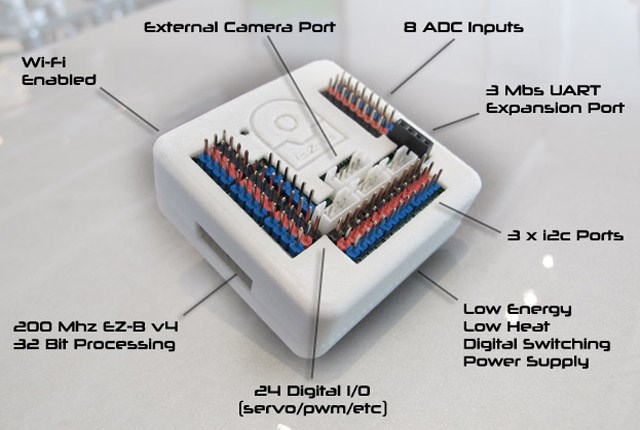
On the EZB V4 digital pins, what color is VCC Pin, Output/Input pin, and Gnd Pin? Is it White(or Blue), Red, Black?
 Websocket Server
— WebSocket server for ARC: accepts clients, stores messages, runs per-message scripts, tracks connection status, supports debug, needs Windows admin
Try it →
Websocket Server
— WebSocket server for ARC: accepts clients, stores messages, runs per-message scripts, tracks connection status, supports debug, needs Windows admin
Try it →
On the EZB V4 digital pins, what color is VCC Pin, Output/Input pin, and Gnd Pin? Is it White(or Blue), Red, Black?

If you now have a 5 vdc potential actually applied to your sensors you will be in good shape. All you need to do to verify this schematic is to use a volt meter and measure the voltage being applied to you sensors before you actually connect them.
Circuit looks right except I don't think the middle pin on the 7805 is the ground, but I don't recall if it is the left or right.
I'll look it up in the morning.
Happy New Year
Alan
Here's one electrical application using your 7805 hardware.
One additional point that I will make is that due to the operating voltages that the EZB(4) are normally exposed to, the capacitors displayed (pictured) in the previous schematic may not be necessary.
@mstephens_42 Your diagram in post #17 is correct... All pinouts are correct... As mentioned, I have made about a dozen of these and they work great....
Richard and Alan, Thanks so much. I'll wire that up and try it out. One question I have is the output pin regulated to 5v in the ezb?
Alan, I'll get your parts printed.
The data pin on the analog and digital ports is 3.3V (white pin) the red pin (power pin) as mentioned equals whatever battery voltage you are using to power your ezb with... If you are using a 7.4 lipo then the red pin will be 7.4V as well... If you use a 12V battery then the red pins will be 12V... Here is the link to the ezb data sheet with all this info on it... EZB4 Data sheet
I was mistaken last night (blame adult beverages). The ground is tthe middle pin. Your diagram is correct.
Alan