
PJ_Dtechy
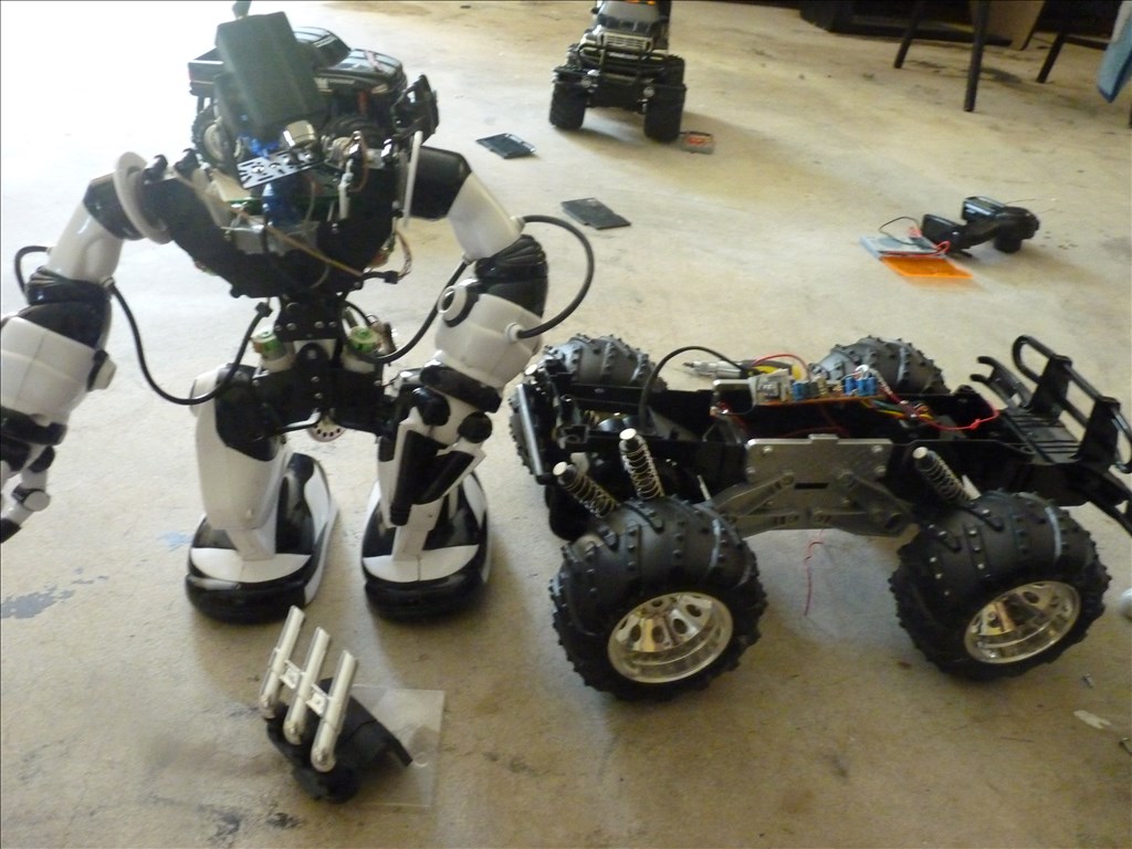
Hey Guys, I am a noob at robotics and slowly getting the hang of it. I have this wonderful monster 1/10 R/C truck that I would like to use as a base for my robosapien and also house my netbook, batteries. I already purchase a Dual H Bridge DC Stepper Motor Drive Controller Board Module Arduino L298N, hopefully it arrive sometime today or tomorrow.
I was able to pull the the controller data sheet online and it is a RX2C controller
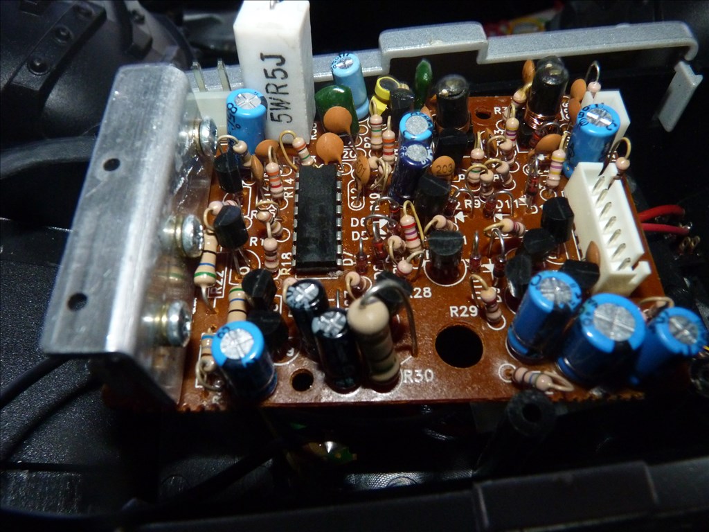
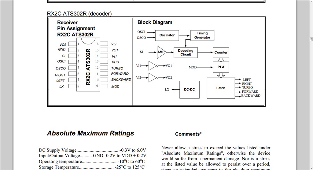
Can I modified or solder the the H-bridge Pin directly to the RX2C chip or do I have to remove the board as so
I will b using Technopro diagram as a guide to wire the H-bridge.
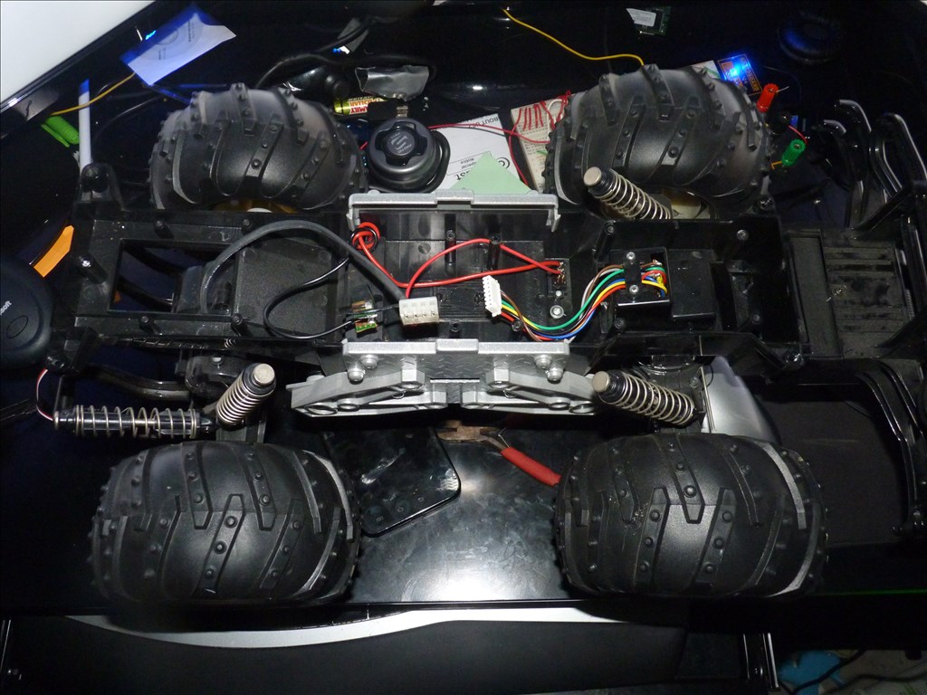
I am just uncertain what route to go, and the wiring schematic for the R/C truck seem different than usual on the rear I have blue, red, white & black going to the rear motor case ( not sure about their functions) and I have red, yellow,green, black, brown, going to the front. I think I only need to be concern about the black & red for the front.

Nice to see people taking interest in my work.
just waiting for my income to be steady so I can purchase the ezb, sabertooth, camera, etc.
diagram again.
How does your truck steer? dc motor? I just tore mine out and modded to fit a mini servo(FYI it works hard so if you take my route use a normal servo if possible).
does it have 2 motors in the back or just one?
seems to me like the back wiring is: red-positive power in black-ground out blue and white-PWM I think your right about only needing to worry about red and black in the front.
Howdy
Below is a project that I found on the web and built. It consist of a RC car, router and microcontroller.
https://www.jbprojects.net/projects/wifirobot/
"Can I modified or solder the the H-bridge Pin directly to the RX2C chip or do I have to remove the board as so" I don't know if you can connect a H-bridge directly to the RX2C chip but in this project I soldered the microcontroller wires right to the underside of the RX2C pins. It worked for me that way.
As for the front wires I never had to mess with them, so no help there. By activating the right/left pins on the chip from the microcontroller it activated the proper wires on the front.
I wonder if this type of steering can be used with EZ-B. This is one tread that I'll be keeping a eye on as it has me thinking.
Hi pj what are your plans for the car?
@Technopro yes I found your diagram to be very helpful.
@Herr Ball thank you, the link was very helpful, I will try the easy way tonight and will tap into the RXC2 chip pin output. The possibilities of me blowing up my circuit board is 50/50. If it is blown will go the hard way and use the H-bridge directly to my motors.
@jstarne1 Dear sir I am a big fan of your work ( project Jarvis). I am also a big fan of Tony Stark Robot. Eventually I will built me a 6th tall robot, but as of right now I use parts I had laying around to put together a mini Jarvis Clone. As far as the car is concern it will house the mini netbook ( running EZ-B, voice software and so on ).
The car primary objective is to be autonomous using ultrasonic sensors and certain scripts.
LOL the H-bridge did arrive today and Clumsy me, misplaced it. Now I have to locate it on my messy desk.
I really appreciate you guys inputs, thank you so much.
Forward and reverse work but having trouble with left and right, any ideas or thoughts?
You should open the cover in the front where the multi-colored cable comes from. There you will find the solenoid or motor for steering...I think it would be the best choice to remove it and insert a rc-servo in this place for full variable steering. The Problem with this "toy" rc-cars is that they don't have a "analog" remote controll, that means you have only full power-gas/no power, full left/straight ahead/full right and nothing between this.
Are you sure that the motor of the car is strong enough to handle all this weight? If you plan to put your netbook on the car, that's ~1,5kg + ~1,5kg for the Torso of Robosapiens + Batteries for all that stuff. Consider that the motor have to pull all the aditional weight, and I think the original steering motor/solenoid would not work with this weight.
I think you should take a look for a real rc-car chassis (not a toy) with a strong Motor and real rc-servo, or a chassis with tracks or six wheels. I think the shocks can be a problem too, because the torso of robosapiens is high and heavy, when you drive left or right it could be that the chassis.
Marc
The Robosapien has been heavily modify, I remove most of the plastic shield case to reduce weight, the head had been cautiously remove to preserve the IR receiver and LED. The 4 D cell batteries ( stupid Heavy) has been remove and replace with two voltage regulator on each leg, power by a 7.2v battery donated by my R/C helicopter. I change my mind about net-book. I would like to preserve some of the mystery when my friends come over. For now is is being operated by bluetooth and later on will add the Uart Wifi server module to EZ-B. As for the Chassis I went with the Dagu Rover 5 2wd chassis. I felt in love with the tank threads, and after two weeks of trial, It is amazing, the level of grip is unbelievable, I simply love it. highly recommend it.
As for the R/C trucks. the speed can be control using the PWM inside the ARC software. It regulate the amount of voltage going trough the motor. My only obstacle is left and right, wanted to use the original built in motor, instead of replacing it with a servo. It is a 1/10 Eztec R/C monster truck, afraid the wheel will be to heavy for the normal servo on my EZ-B kit. Will work on it wednesday and updated this post once a successful result. Since someone else from this Forum is interested in doing the same thing with their R/C truck, I'm now more interested to complete it. I have about 4 R/C to play with, we shall see. cool