
Ellis
USA
Asked
— Edited
I have been trying to find a real simple way to control an led light strip with my EZ-B. I have seen several circuits that I could make to do the job but would rather buy a mosfet circuit. I need to control a 12v light strip with 5v EZ-B signal. I found this board and wanted what the forum thinks.
https://www.energiazero.org/arduino_sensori/arduino%20irf520%20mosfet%20driver%20module.pdf

rb550f Thanks for the hbridge idea. I can try that but it only cost $2.00 for the Mosfet board.
I think you have a good idea though.
@Ellis,
Let's start from the begin.
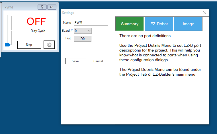
If you add PWM slider:
and play with the control can you switch on, off, dim the lights ?@Ellis - right on for what PTP said. When troubleshooting, you need to think about what is the simplest form that will function.
Using a new circuit with LED controls and script you have not used before those introduce several different points where things "could" go wrong.
So PTP and I were trying to suggest ways to bring the complexity down to something simple - which is to ask the question "Does your circuit work with the PWM slider to control the lights?" - If not we need to look at your circuit and connections.
If it does work we can move onto seeing why the PWM circuit is not reacting to the sound servo PC control.
Does that make sense?
Are you able to turn on the leds with just a port to on?. If not you might need to use a ttl level shifter on your signal input on your mosfet board. I have used these on relay boards that would not work with ezb logic level. They cost less than $2 on Ebay.
@Ellis,
I share Justin's opinion you need to go back to the begin and troubleshoot the wiring, component and only then the software. Rick's script works.
It depends how valuable is your time and how patient you are.You spent a couple bucks in a cheap Chinese supplier (nothing against the Chinese) the problem is the lack of support, lack of documentation and misleading information.
So no support hein !?
Looking to the PCB: 1 x mosfet, 2 x resistors and maybe a led.
this is my guess: 1 resistor is used with the led, the other one must be pull down There is no optocoupler to separate the input/output, so a common ground is used. There isn't a amplifier transistor so the Mosfet gate uses the EZB signal (3.3v) to drive.
This is a simple diagram:
It's obvious you share a common ground and you don't need EZB's VCC.
The next question is to know the gate to source threshold voltage at which the mosfet turns on.
looking the specs: https://www.vishay.com/docs/91017/91017.pdf
relevant info:
between 2.0-4.0. EZB signal is 3.3v
There are other factors like temperature, component quality, tolerance etc I don't gamble so i would say that 3.3v is not enough to drive the Mosfet.
Maybe you can get lucky.
If you want to drive the mosfet you will need to amplify/convert the signal
another detail:
With 4.5V you can get current just a bit higher than 1A. I can't guess how much current you can drive with 3.3v but it will be lower. This is not an issue If your lights need less than 1A.