Ellis
USA
Asked
— Edited
Mosfet Control
I have been trying to find a real simple way to control an led light strip with my EZ-B. I have seen several circuits that I could make to do the job but would rather buy a mosfet circuit. I need to control a 12v light strip with 5v EZ-B signal. I found this board and wanted what the forum thinks.
https://www.energiazero.org/arduino_sensori/arduino%20irf520%20mosfet%20driver%20module.pdf

Seems reasonable to me. I don't have experience with that board but I do have experience with IRF540 MOSFETs which are commonly used across the industry. The IRF520 is a close relative I just hope you don't need more than 5Amps for your light.
Thanks Jeremy. I am using them mostly for small projects but that is a great point. I really like them because I can almost just plug them in and go.
Or just use an inexpensive hbridge motor driver ,it's easy to connect to ezb.
Do you use just 1/2 of the hbridge.
Yes just use 1/2 of hbridge,works great.
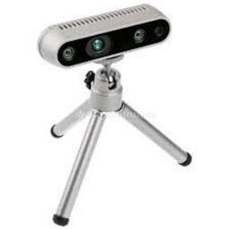
I am trying to get the three led lights in my robots mouth to light up with sound servo pc. I am using an IRF29 mosfet driver module with 12v in and out. The signal is coming from my Lotiny microprocessor. Here are the picture and specs for the mosfet module.
https://www.newegg.com/Product/Product.aspx?Item=9SIADU75TV6663&ignorebbr=1&nm_mc=KNC-GoogleMKP-PC&cm_mmc=KNC-GoogleMKP-PC-_-pla-_-EC+-+Circuit+Protection-_-9SIADU75TV6663&gclid=EAIaIQobChMI35H7oM6Q3gIV2EwNCh2SZwoEEAkYAyABEgImtvD_BwE&gclsrc=aw.ds
Specification *Size: 34mm * 26 mm *Weight: 10 g *Voltage: 3.3 V, 5 V *Ports: Digital Level *Output load voltage: 0-24V *Output load current: ?5A (1A above need to add heat sink)
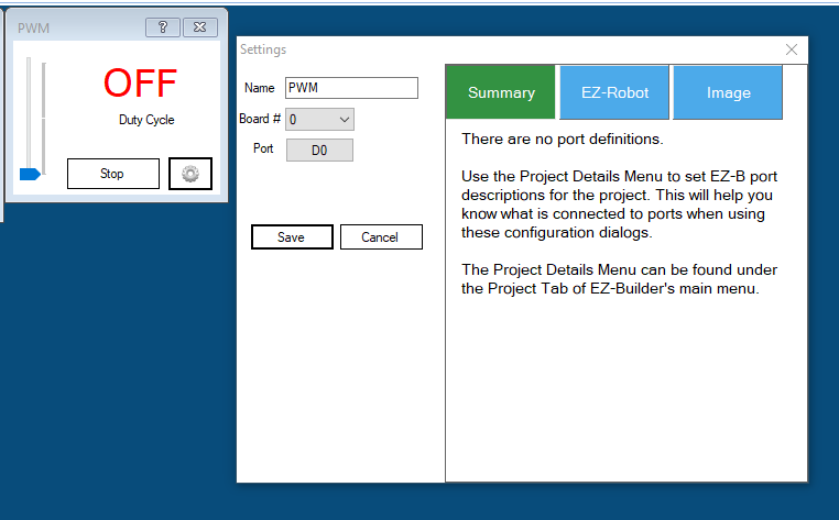
I have added this code to the Lotiny from tutorial and changed port to D0:
Sound servo to PWM range Script
Author: Rich
Version: 1.0.0
Date: 25th June 2013
Variables (do not adjust)
$soundvalue = auto
$pwmvalue = 0
Main script
Set the start point for the never ending loop
:loop
Check the variable from the Sound servo control against a list of pre-determined levels (you may need to change these) and set the PWM value to suit.
IF ($soundvalue < 10) $pwmvalue = 0 ELSEIF ($soundvalue < 20) $pwmvalue = 10 ELSEIF ($soundvalue < 30) $pwmvalue = 20 ELSEIF ($soundvalue < 40) $pwmvalue = 30 ELSEIF ($soundvalue < 50) $pwmvalue = 40 ELSEIF ($soundvalue < 60) $pwmvalue = 50 ELSEIF ($soundvalue < 70) $pwmvalue = 60 ELSEIF ($soundvalue < 80) $pwmvalue = 70 ELSEIF ($soundvalue < 90) $pwmvalue = 80 ELSEIF ($soundvalue < 100) $pwmvalue = 90 ELSE $pwmvalue = 100 ENDIF
Set the PWM with the value chosen above (you may need to change the port to suit)
PWM(D0, $pwmvalue)
Add any other PWM ports above this line with PWM(PortNo, $pwmvalue)
Sleep for 100ms to avoid saturation (you may need to adjust this to increase accuracy or increase stability. Reduce the delay for better accuracy, increase for better stability)
Sleep(100)
Jump back to the start
Goto(loop)
I installed Sound servo Pc and configured it according to the tutorial. When I run sound synthesis message it plays on my computer but dos not light up the lights on my robots mouth. I have checked the 12v going in and it is ok. I get no voltage on the out. I have been working on this for around a week and still do not have the system working. Any ideas?
Does manually setting via a script the PWM of DO to control a light work for you?
PWM (digitalPort, speed) Set the PWM (Pulse Width Modulation) to the desired duty percentage cycle This simulates voltage on the specified pin (Between 0 and 5v) PWM Value is between 0 and 100
The existing code does not work for me. I have used the above code only changing the port. That seems to be the only item that needed to be changes. I maybe put the script in the wrong place. I put it in the
Are you saying to change the speed variables to larger numbers (over 100)? It now seems like no signal is coming to the mosfet board?
Shouldn't I be able to hear the robot voice and light leds at the same time. Maybe I have to do something to assign the speaker and the Lotiny in Windows.
I really appreciate you help. I think it is something simple but, as of yet, not been able to find it.