
jstarne1
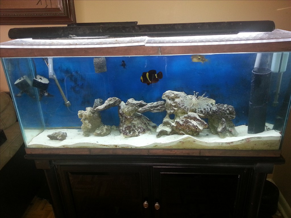
Ez Robot community I wanted to introduce my latest application of this system. Some members hear already know I keep two salt water aquariums one coral which unfortunately died off and my predator tank. Sea life needs delicate balance maintained in their little ecosystem. Things like light spectrum , temperature, ph balance , current of water , nitrate and ammonia levels and calcium levels. These things take a practiced hand to maintain. I am building a new system and using ez b to monitor salinity, nitrates and ammonia, temp , water current flow and the ph. The ADC ports are useful for these and EZ board can control the current and switching to a backup power supply ( a apc for computers inside the cabinet to keep ezb and pumps powered). Also the ezb can turn on and off night , morning , day , and evening lighting settings. With a custom injection device im designing ezb can provide nutrients , calcium and even medicine if levels are out of wack. I started the build today and I am very excited!

I have regulated 5 volts going to ezb. That should be fine right?.
5v to 17v so yes, although ideal voltage is 7.2v according to the manual
Awesome Josh! an amazing build pictorial with an EZ-B at the heart. I belive this tread holds the record for the longest on the Forum! professional build too I might add
Thankyou irobot! , about the thread length.. The Jarvis omnibot 2000 build has 200 pages in the first thread and more in the second getting ready for paint. Thats a big project I started in January. Thankyou for your support! I TRY to make my builds detailed enough a novice builder could copy my results.
Thanks for the clarification on the TIP120! Where did you find the diagram?
here is a link on how to wire a TP120 correctly and in the article is shows using arduino like JOSH HAS
it shows for motors and induction loard like relays that the diode is across the motor or relay coil also shows that is controlling light it doest need the diode
how to use a TIP120
DIODE IS FOR COIL SURGE KICKBACKS or way to call is is BACK EMF can place accross he transistor but does do as good as across the coil the diode works like a voltage clamp little info about a darlington is is 2 npn transistors connected together to get double the power PNP darlington is a little better but needs a inverter circuit using another transistors
here is some info on what the diode is for You can see that in 2 of the 3 illustrations, there is a diode parallel to the device we are powering. Any time you are powering a device with a coil, such as a relay, solenoid, or motor, you need this guy, and don't leave home without it. What happens is when you stop powering the coil, a reverse voltage, up to several hundred volts, spikes back. This only lasts a few microseconds, but it is enough to kill our transistor. So this diode (only allows current to pass one way) is normally facing the wrong direction and does nothing. But when that voltage spikes comes flowing the opposite direction, the diode allows it to flow back to the coil and not the transistor. We will need a diode fast enough to react to the kickback, and strong enough to take the load. A rectifier diode like the 1N4001 or SB560 should do the job. If you are looking for extra protection you could use an optoisolator between the Arduino and the transistor. An optoisolator optically isolates both sides (high and low power) of the circuit so the high-voltage can not possibly can not come back to the microcontroller
also says about on using optoisolator witch is much better
I just took a video testing the system with two lights. Im uploading to YouTube now.
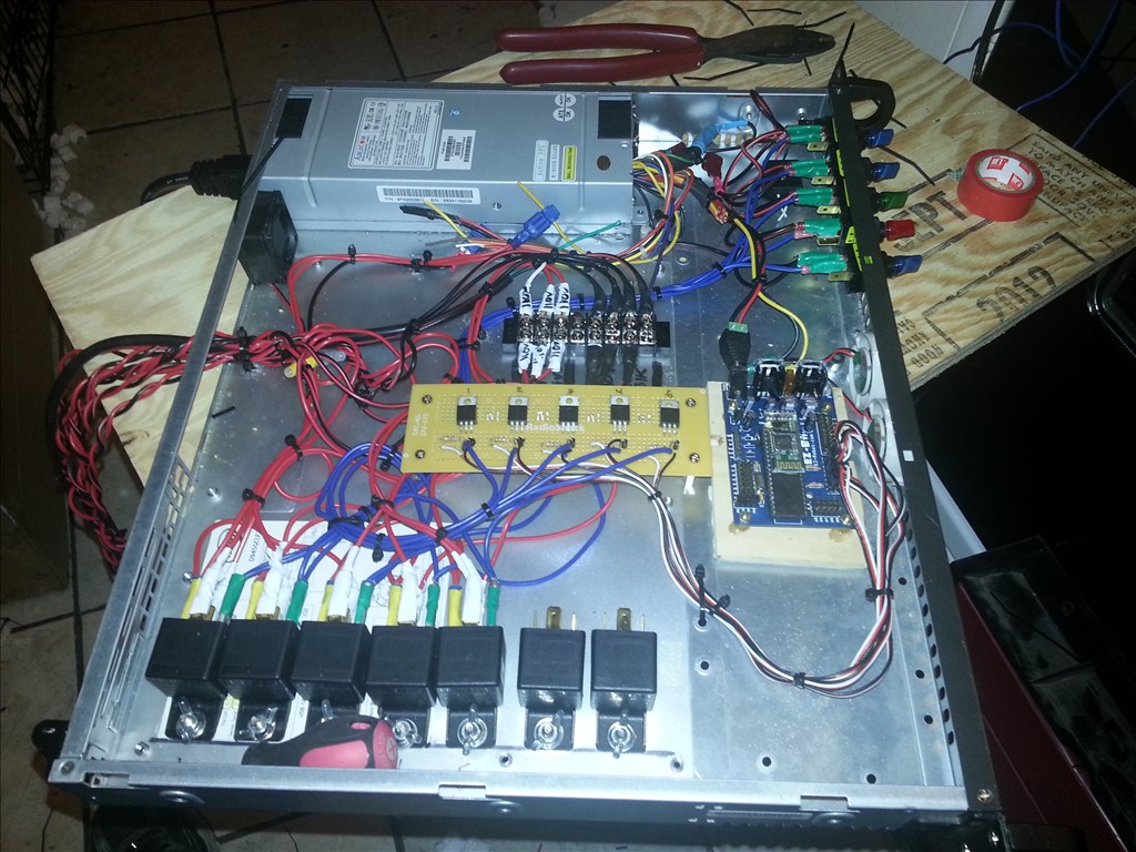
This is the Smart Aquarium controller with 5 relays setup for all the lights right now. Next will be the wave generator which is already wired.