
L298n H-Bridge
Setting Up L298n H-Bridge This tutorial assumes only a single combined speed control for both motors. For independent speed of each motor the tutorial will be slightly different - See post #2 of this topic.
Assuming ports D15, D16, D17, D18 & D19 D15 Signal > Left Trigger A (In 1) D16 Signal > Left Trigger B (In 2) D17 Signal > Right Trigger A (In 3) D18 Signal > Right Trigger B (In 4)
D19 VCC > H-Bridge 5V D19 Ground > H-Bridge Ground D19 Signal > H-Bridge ENA & ENB
D19 Signal will need to be connected to 2 pins on the H-Bridge and the jumpers on the H-Bridge removed. I made a Y cable out of a couple of jumper cables.
Connect the positive of the battery to the H-Bridge VCC
Connect motor 1 to the Out 1 and Out 2 terminals Connect motor 2 to the Out 3 and Out 4 terminals
In ARC add a 4 Wire H-Bridge control and a PWM control.
Set up the H-Bridge control as the above D15 to D18 on LTA, LTB, RTA and RTB Set up the PWM control to D19
To use, set the PWM to 100% (or a lower value if you want it slower) - I have mine set to 100% in an init script that is run on successful connection of the EZ-B. Use the H-Bridge control and the motors should move.
Here is a project with both controls added, you can save it and merge it with your project (or open it and test the H-Bridge). It's also accessible in ARC by opening from the cloud.
Note: The PWM wire is optional. If you wanted to save a digital port and lose speed control you could connect any of D15 to D18's VCC to the H-Bridge 5V and any of the D15 to D18's Ground to the H-Bridge Ground. Keep the jumpers on between ENA and 5v and ENB and 5v.
If your H-Bridge looks different, they are pretty much all much of a muchness. A H-Bridge generally has 4 inputs to control the 2 motors plus 1 or 2 inputs for speed control. The same principle as above can be applied.
Signal wires from Digital ports to each of the inputs to control the motors. Generally labeled In1 to In4 or AIn1, AIn2, BIn1 and BIn2. Signal wires (this can be combined for 1 port if you don't want individual speed control from side to side) for the PWM or speed. Generally labelled as ENa and ENb. +5V or VIn is generally the 5V from the EZ-B Vm is generally the supply to the motors taken from the battery. Ground is always Ground, taken from any ground since it's a common ground.
A simple truth table for how the H-Bridge works.
 In4 | In3 | In2 | In1 | Function
-----+-----+-----+-----+--------------
  0  |  0  |  0  |  0  | Stop/Free Wheel
  0  |  0  |  0  |  1  | Motor 1 Forward
  0  |  0  |  1  |  0  | Motor 1 Reverse
  0  |  0  |  1  |  1  | Motor 1 Brake
  0  |  1  |  0  |  0  | Motor 2 Forward
  1  |  0  |  0  |  0  | Motor 2 Reverse
  1  |  1  |  0  |  0  | Motor 2 Brake
So to use that on the robot, setting digital to on (1) and off (0) as follows
 In4 | In3 | In2 | In1 | Function
-----+-----+-----+-----+--------------
  0  |  1  |  0  |  1  | Robot Forward
  1  |  0  |  1  |  0  | Robot Reverse
  1  |  0  |  0  |  1  | Robot Turn Left (or right depending on motor orientation)
  0  |  1  |  1  |  0  | Robot Turn Right (or left depending on motor orientation)
  0  |  0  |  0  |  0  | Robot Stop
EZ-B V4 Usage
With the EZ-B V4 there is a slight difference when connecting the L298n H-Bridge up in that the Vcc pins of the V4 have the same voltage as VIn i.e. if you supply the EZ-B V4 with a 7.4v 2s LiPo battery you will get 7.4v on the Vcc pins of the EZ-B.
The L298n H-Bridge, as previously explained has a terminal for +5V which, on the EZ-B V3 was fine to supply from one of the digital ports Vcc however with the V4 this is not the case.
Rather than supply the L298n with +5V we need to not connect this terminal and press the switch on the H-Bridge so that it uses it's on board regulators to provide its own 5V from the Vcc supplied.
All other connections remain as previously explained.
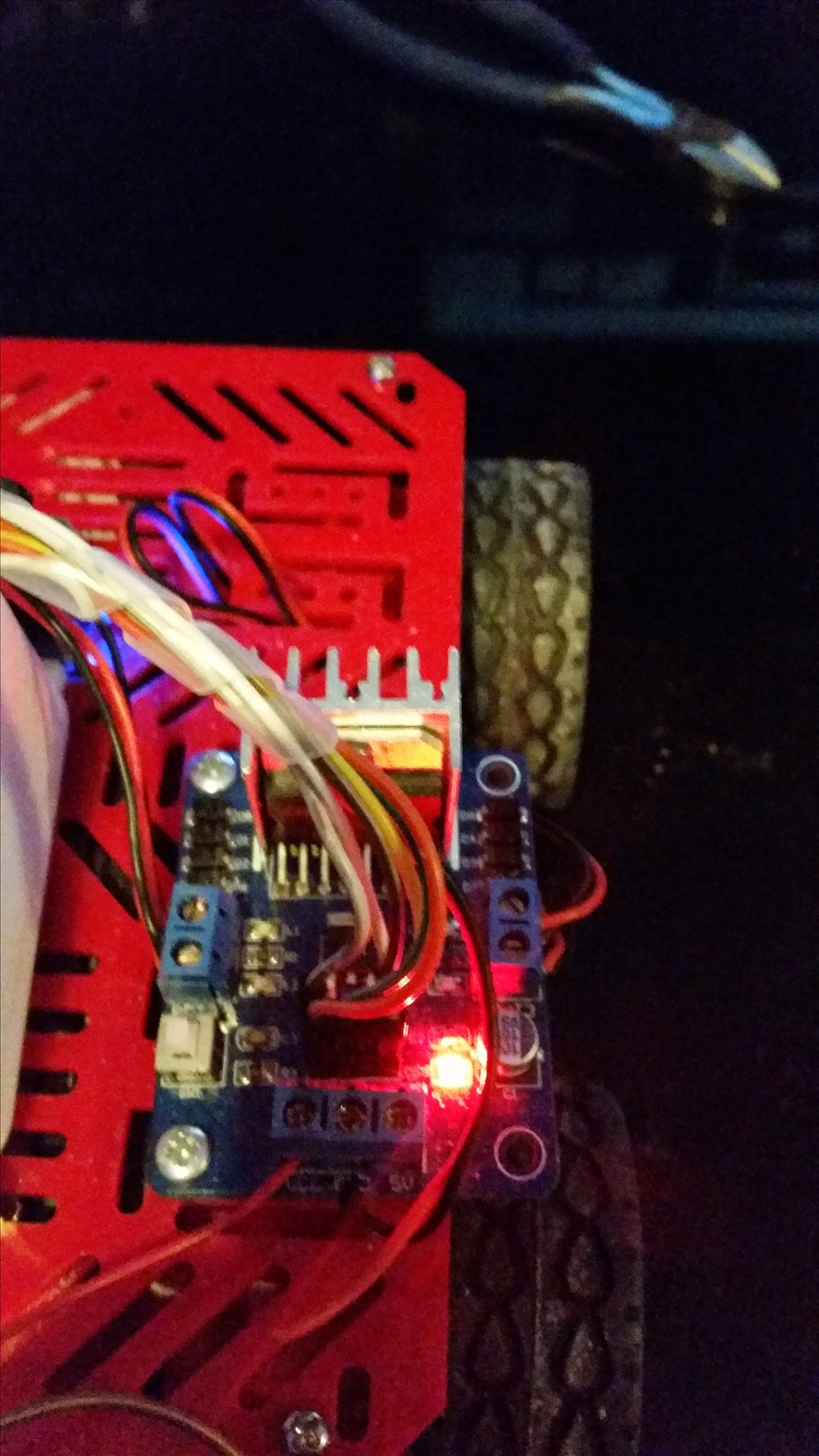
Pushing this button will enable the on board regulators. When enabled it may indicate so with a red LED.
On the EZ-B side, the connections would be pretty much as previously with the exception of the Vcc. On upgrading my test bot I simply disconnected the Vcc on the H-Bridge side so that my connections wouldn't require changing.
On the H-Bridge side, connections remained the same as previously however the +5V is disconnected.
That's all there is to it.
Update: 17/06/2014 (or 06/17/2014 if you write your dates wrong...)
Alternative wiring for a simpler method
The connections on the L298n are simply;
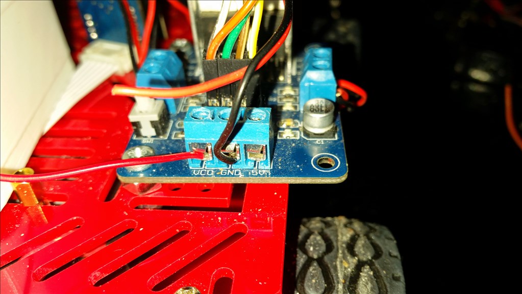
Vcc = Motor Supply Positive Gnd = Motor Supply Ground (ensure this is common if using more than one supply) +5V = Not Connected
In1 = Digital Port Signal (i.e. D8) In2 = Digital Port Signal (i.e. D9) In3 = Digital Port Signal (i.e. D10) In4 = Digital Port Signal (i.e. D11) EnA = Digital Port Signal (i.e. D12)* EnB = Digital Port Signal (i.e. D13)*
- EnA & EnB connections optional for speed control, If speed control is not required connect the two jumpers which come with the L298n to link EnA to the +5v pin to it's right and EnB to the +5v pin to it's left. If combined speed control is required (i.e. one speed control for both channels) a Y-cable can be used to connect both EnA and EnB to one Digital Port Signal (i.e. D12).
No ground or Vcc from the EZ-B to the L298n is required if you have a single source for both EZ-B and L298n or if you have a common ground.
You must make sure you press the switch to enable the on board 5V regulator circuit otherwise it will not operate
Some photos (I'll change them once I get chance to edit and tidy them up but no idea when I'll get the chance so here's the unedited ones).
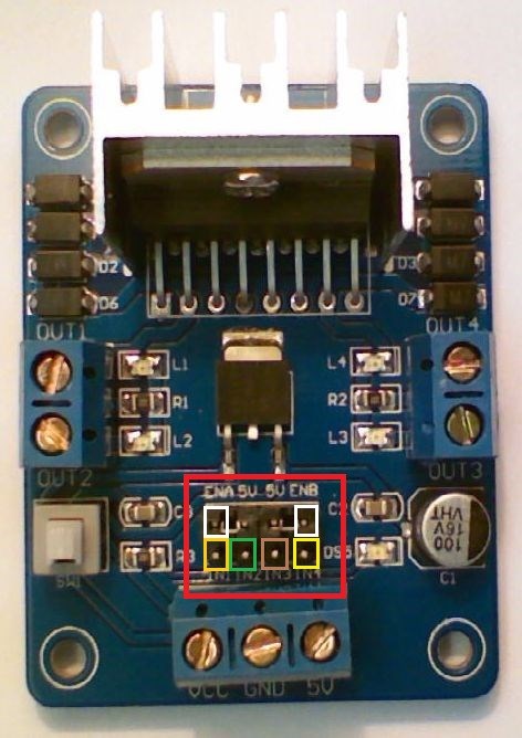
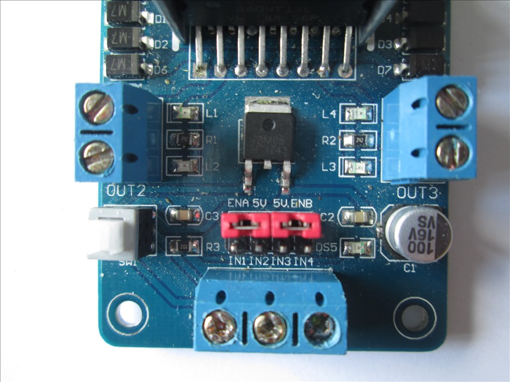
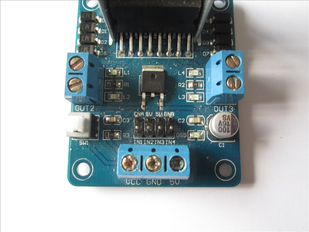
The L298n in it's stock state
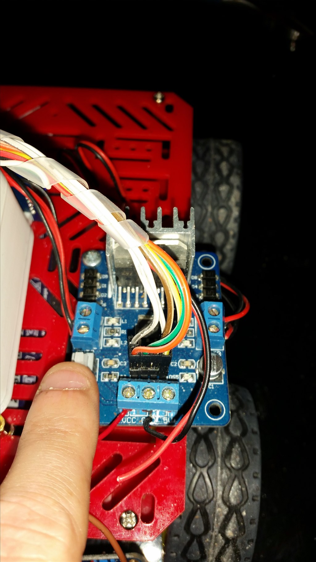
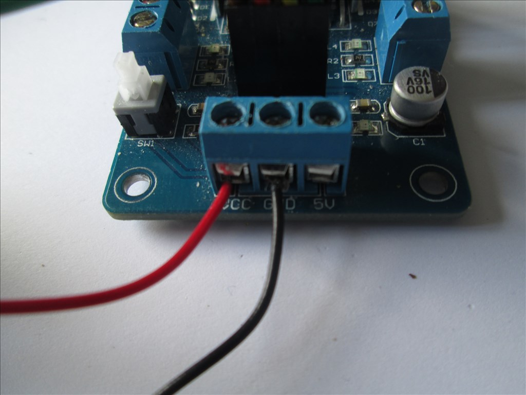
The L298n wired power connections
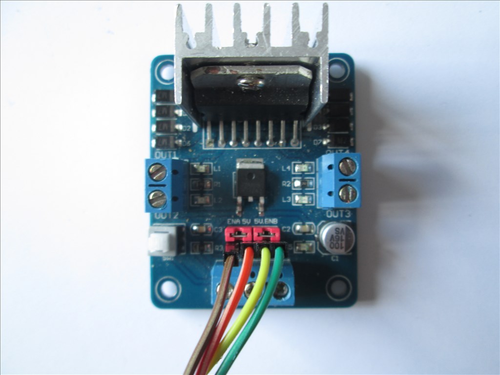
The L298n wired for no speed control
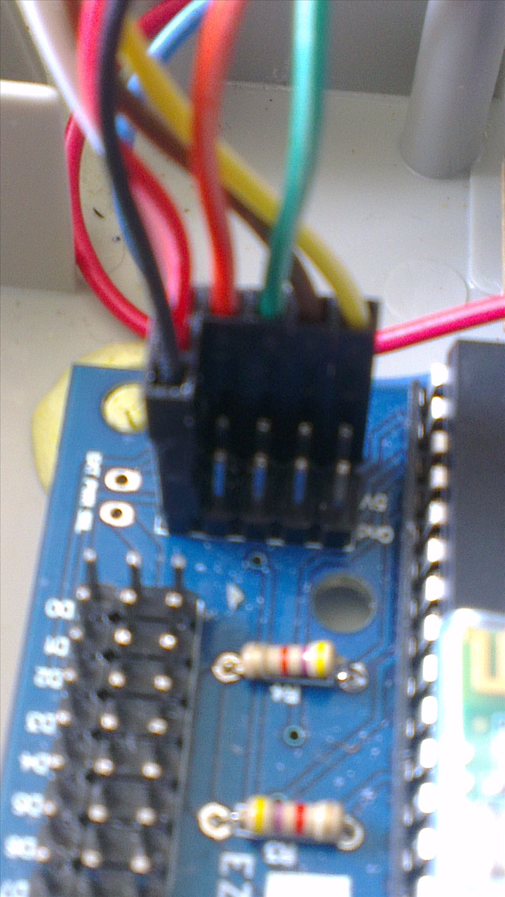
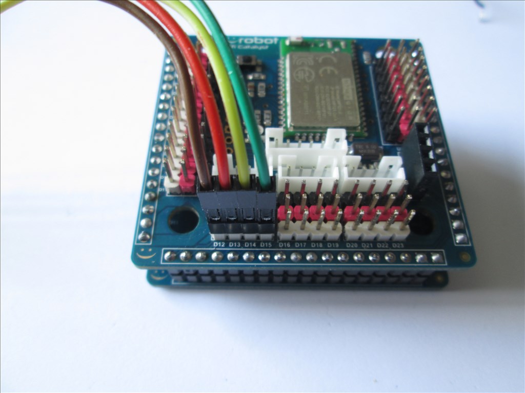
The EZ-B V4 wired for no speed control
The L298n with the jumpers removed
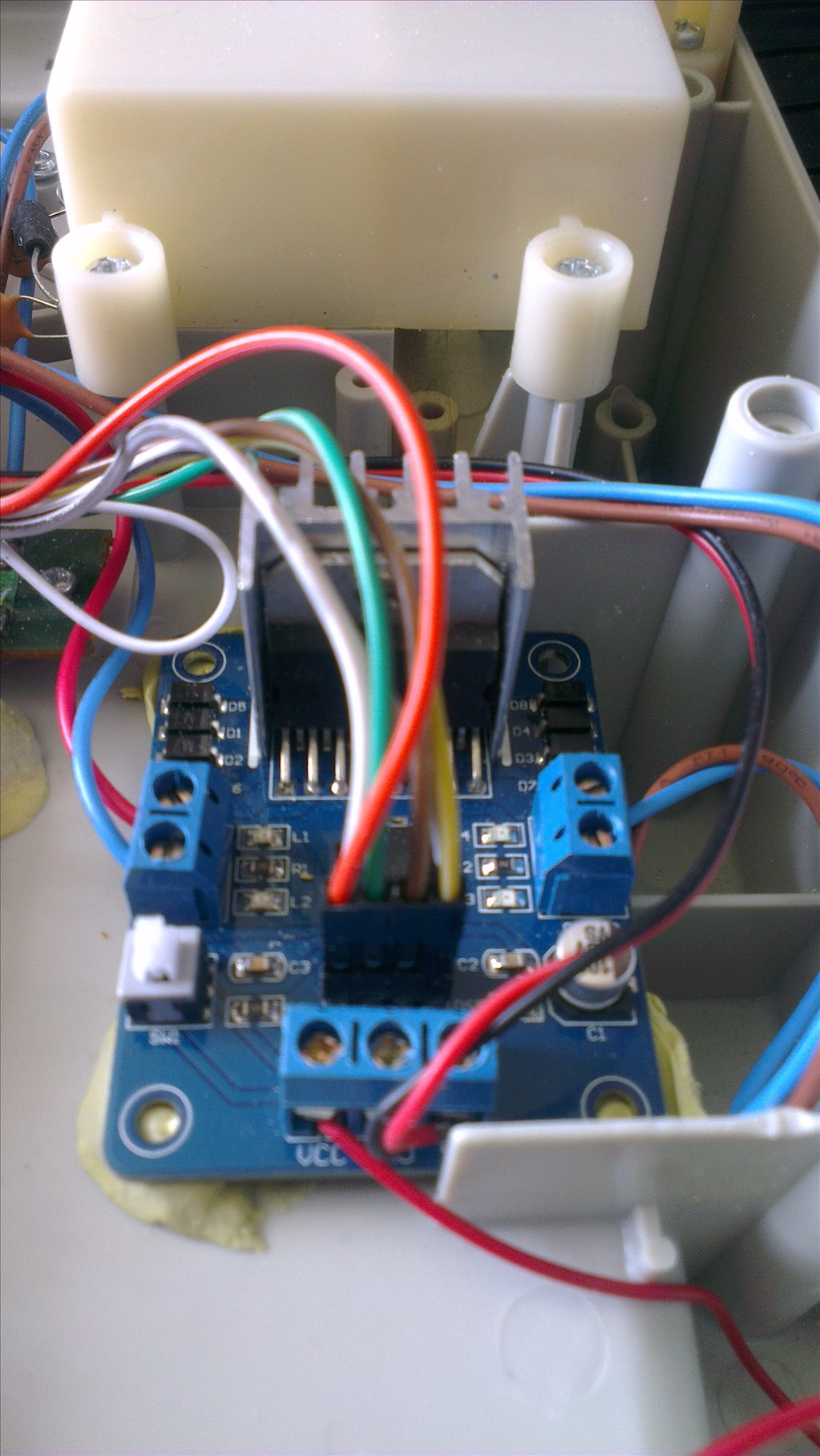
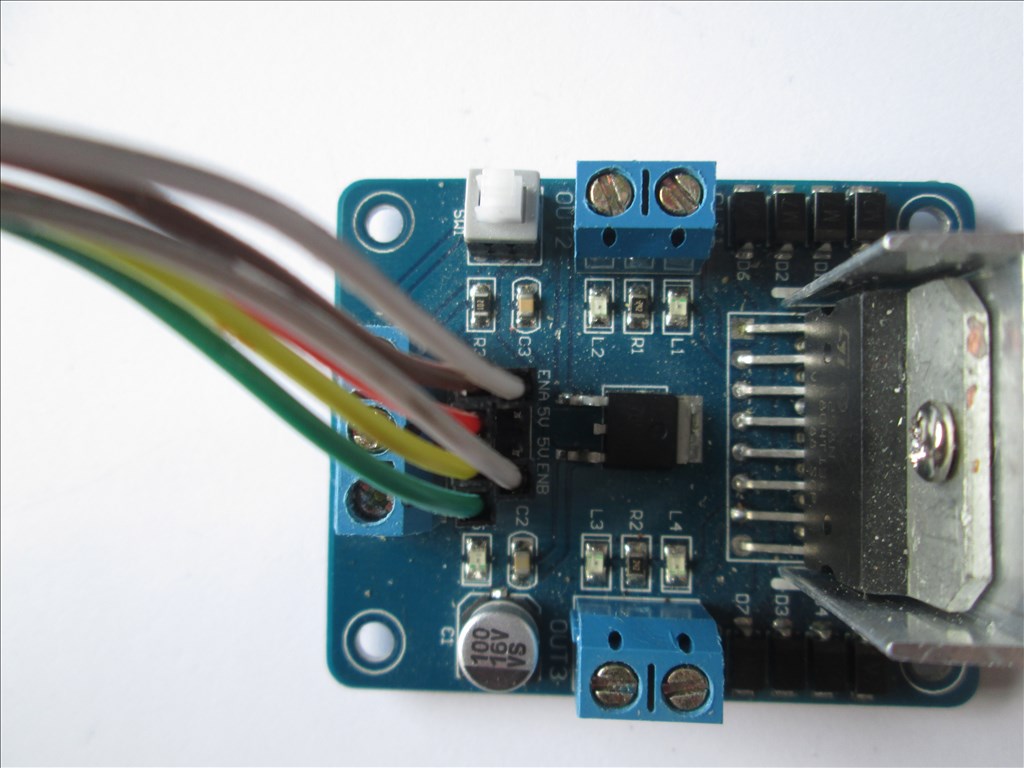
The L298n wired for common speed control (1 PWM adjusts the speed of both channels). White wires is a Y cable, 2 to 1 with the 2 at the L298n end
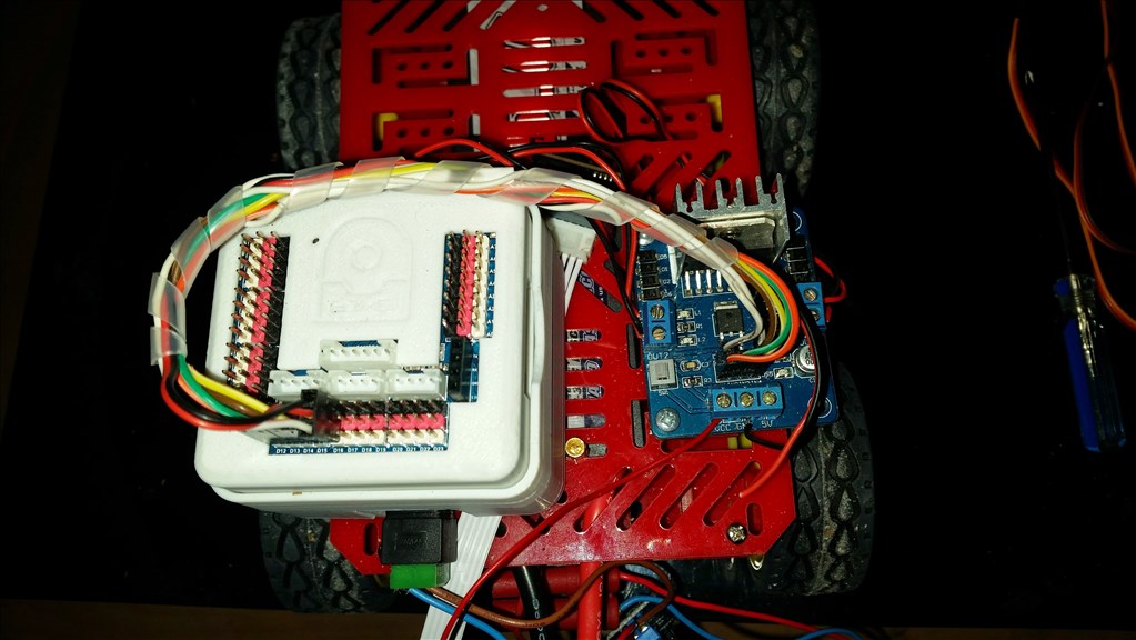
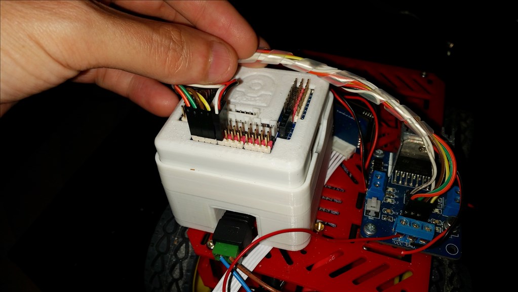
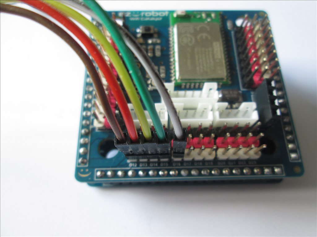
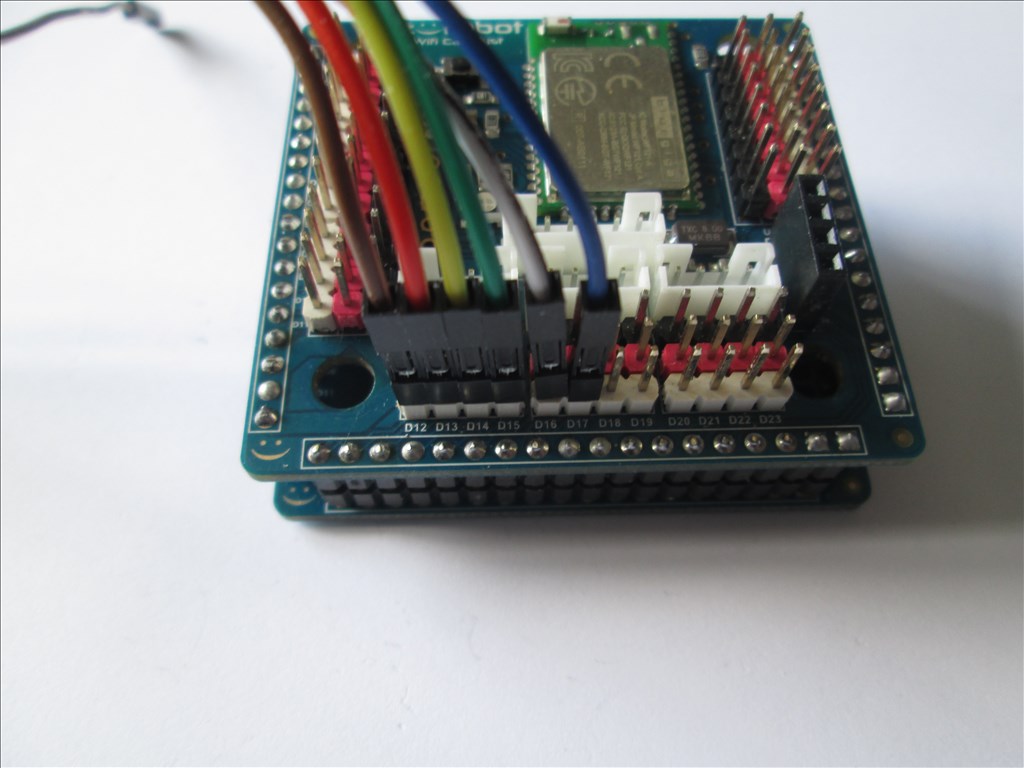
The EZ-B V4 wired for common speed control (1 PWM adjusts the speed of both channels). White wire is a Y cable, 2 to 1 with the 1 at the EZ-B V4 end
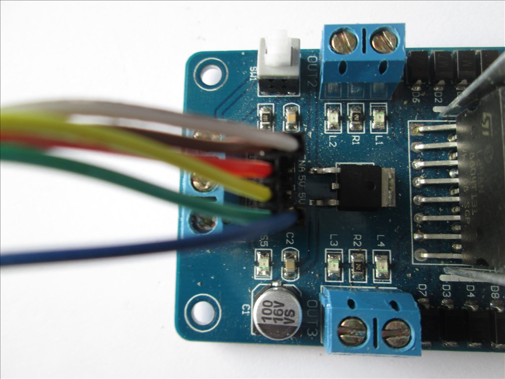
The L298n wired for independent speed control
The EZ-B V4 wired for independent speed control

What is the +5v terminal used for on the L298? confused
If you don't want to use the on board regulator you can supply it with +5V from other means. On the V3 I don't use the L298n H-Bridge's regulator so I take a Vcc from a digital port to the L298n.
On the V4, since it's not regulated, use of the on board regulator is required - press the switch on the l298n to enable it. Some L298n H-Bridges don't have an on board regulator so these will need a +5V to the +5V terminal.
Thanks Rich. Btw, I could still do with your help on this topic, specifically post #13. I've followed your great tutorial, but I just need a bit more help finishing off if that's cool.
Cheers, Steve. (--EDIT--)
Forget the above post. Completely forgot I had this question answered in another thread. It's been a busy week with hospital appointments ect. Sorry about that eyeroll
I just received a H-bridge. Super fast delivery. This tutorial will be a great help ! Thanks for posting
Cheers Johan
I heard that H bridges can be used as brakes.
I am trying to set up an off-brake for every single servo in my robot. Lets assume I will be using 24 servos so I need a cheap solution that is tiny.
So far I have tried using a Y splitter from the PWM cable that connects both a servo and a tiny RC Switch to a tiny Pull Solenoid. What I hope will happen is that the RC switch will trigger the pull solenoid whenever there is any pulse at all. That would pull the brake away instantly whenever the servo moves and a spring would force the brakes on whenever the servo receives no signal. So by default, the brakes are always on. When the servo wants to move, the brake releases.
Unfortunately, all the RC switches have only activated when the servo rotates clockwise more than 50% of the way. I want it to activate when there is any pulse at all. Would an H bridge help, are there RC switches specific to my needs or is there a better solution?
It would be great if someone could answer the questions in the description of this video if you have a YouTube account for commenting. It will help all of you immensely as cybernetic engineers.Thanks
Search TIP 122 circuit in the search area.
I'm feeling really stupid. I bought the l298n H-bridge and have it hooked up to the exact digital ports as you display. The only difference is that I am trying to drive a 12VDC motor so I have a 12VDC supply connected to the Vcc on the H-bridge. But when I press any of the arrow keys nothing happens. No voltage on the out pins of the H-bridge. What could be the problem? Yes, I have the pushbutton pressed and the red led is lit. I don't think I need to write any script?
@Castlephelps.
Are you using 2 different power supplies, one for the EZ-B, and one for the motors? If so, do you have a common ground wire from your 12v motors supply ground terminal to an EZ-B ground pin or the EZ-B's power supply ground?