L298n H-Bridge
Setting Up L298n H-Bridge This tutorial assumes only a single combined speed control for both motors. For independent speed of each motor the tutorial will be slightly different - See post #2 of this topic.
Assuming ports D15, D16, D17, D18 & D19 D15 Signal > Left Trigger A (In 1) D16 Signal > Left Trigger B (In 2) D17 Signal > Right Trigger A (In 3) D18 Signal > Right Trigger B (In 4)
D19 VCC > H-Bridge 5V D19 Ground > H-Bridge Ground D19 Signal > H-Bridge ENA & ENB
D19 Signal will need to be connected to 2 pins on the H-Bridge and the jumpers on the H-Bridge removed. I made a Y cable out of a couple of jumper cables.
Connect the positive of the battery to the H-Bridge VCC
Connect motor 1 to the Out 1 and Out 2 terminals Connect motor 2 to the Out 3 and Out 4 terminals
In ARC add a 4 Wire H-Bridge control and a PWM control.
Set up the H-Bridge control as the above D15 to D18 on LTA, LTB, RTA and RTB Set up the PWM control to D19
To use, set the PWM to 100% (or a lower value if you want it slower) - I have mine set to 100% in an init script that is run on successful connection of the EZ-B. Use the H-Bridge control and the motors should move.
Here is a project with both controls added, you can save it and merge it with your project (or open it and test the H-Bridge). It's also accessible in ARC by opening from the cloud.
Note: The PWM wire is optional. If you wanted to save a digital port and lose speed control you could connect any of D15 to D18's VCC to the H-Bridge 5V and any of the D15 to D18's Ground to the H-Bridge Ground. Keep the jumpers on between ENA and 5v and ENB and 5v.
If your H-Bridge looks different, they are pretty much all much of a muchness. A H-Bridge generally has 4 inputs to control the 2 motors plus 1 or 2 inputs for speed control. The same principle as above can be applied.
Signal wires from Digital ports to each of the inputs to control the motors. Generally labeled In1 to In4 or AIn1, AIn2, BIn1 and BIn2. Signal wires (this can be combined for 1 port if you don't want individual speed control from side to side) for the PWM or speed. Generally labelled as ENa and ENb. +5V or VIn is generally the 5V from the EZ-B Vm is generally the supply to the motors taken from the battery. Ground is always Ground, taken from any ground since it's a common ground.
A simple truth table for how the H-Bridge works.
 In4 | In3 | In2 | In1 | Function
-----+-----+-----+-----+--------------
  0  |  0  |  0  |  0  | Stop/Free Wheel
  0  |  0  |  0  |  1  | Motor 1 Forward
  0  |  0  |  1  |  0  | Motor 1 Reverse
  0  |  0  |  1  |  1  | Motor 1 Brake
  0  |  1  |  0  |  0  | Motor 2 Forward
  1  |  0  |  0  |  0  | Motor 2 Reverse
  1  |  1  |  0  |  0  | Motor 2 Brake
So to use that on the robot, setting digital to on (1) and off (0) as follows
 In4 | In3 | In2 | In1 | Function
-----+-----+-----+-----+--------------
  0  |  1  |  0  |  1  | Robot Forward
  1  |  0  |  1  |  0  | Robot Reverse
  1  |  0  |  0  |  1  | Robot Turn Left (or right depending on motor orientation)
  0  |  1  |  1  |  0  | Robot Turn Right (or left depending on motor orientation)
  0  |  0  |  0  |  0  | Robot Stop
EZ-B V4 Usage
With the EZ-B V4 there is a slight difference when connecting the L298n H-Bridge up in that the Vcc pins of the V4 have the same voltage as VIn i.e. if you supply the EZ-B V4 with a 7.4v 2s LiPo battery you will get 7.4v on the Vcc pins of the EZ-B.
The L298n H-Bridge, as previously explained has a terminal for +5V which, on the EZ-B V3 was fine to supply from one of the digital ports Vcc however with the V4 this is not the case.
Rather than supply the L298n with +5V we need to not connect this terminal and press the switch on the H-Bridge so that it uses it's on board regulators to provide its own 5V from the Vcc supplied.
All other connections remain as previously explained.
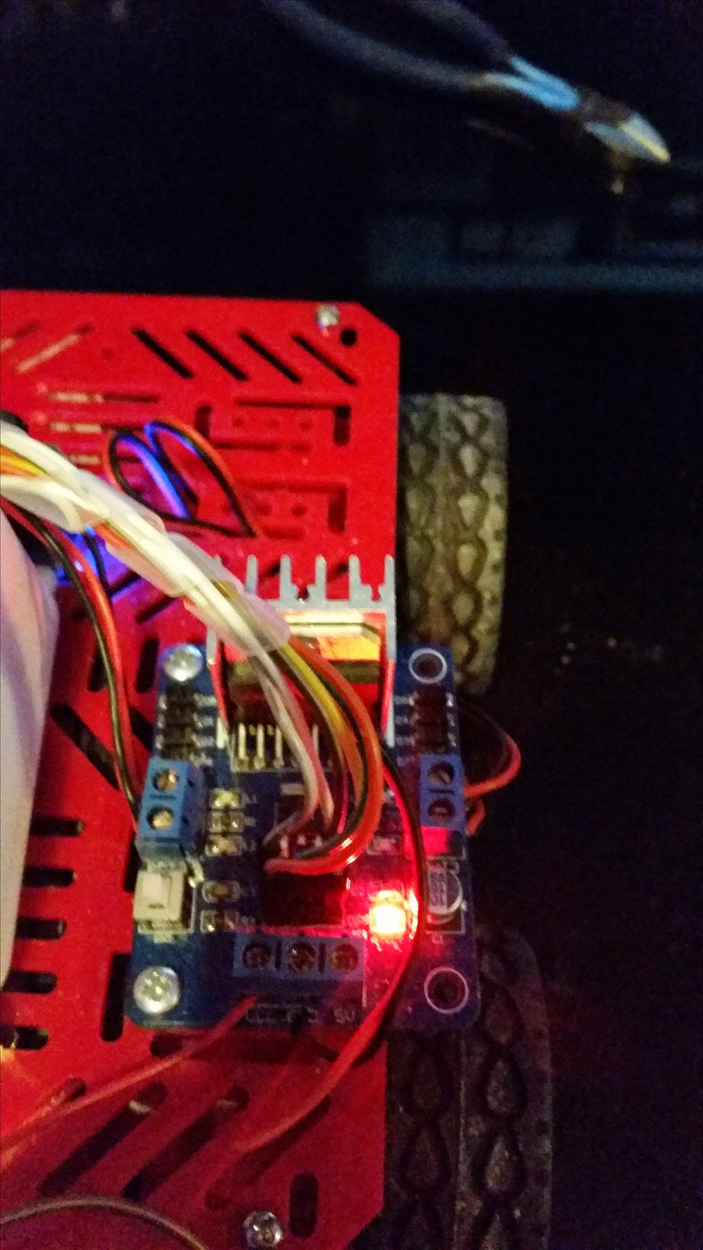
Pushing this button will enable the on board regulators. When enabled it may indicate so with a red LED.
On the EZ-B side, the connections would be pretty much as previously with the exception of the Vcc. On upgrading my test bot I simply disconnected the Vcc on the H-Bridge side so that my connections wouldn't require changing.
On the H-Bridge side, connections remained the same as previously however the +5V is disconnected.
That's all there is to it.
Update: 17/06/2014 (or 06/17/2014 if you write your dates wrong...)
Alternative wiring for a simpler method
The connections on the L298n are simply;
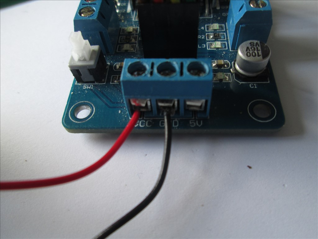
Vcc = Motor Supply Positive Gnd = Motor Supply Ground (ensure this is common if using more than one supply) +5V = Not Connected
In1 = Digital Port Signal (i.e. D8) In2 = Digital Port Signal (i.e. D9) In3 = Digital Port Signal (i.e. D10) In4 = Digital Port Signal (i.e. D11) EnA = Digital Port Signal (i.e. D12)* EnB = Digital Port Signal (i.e. D13)*
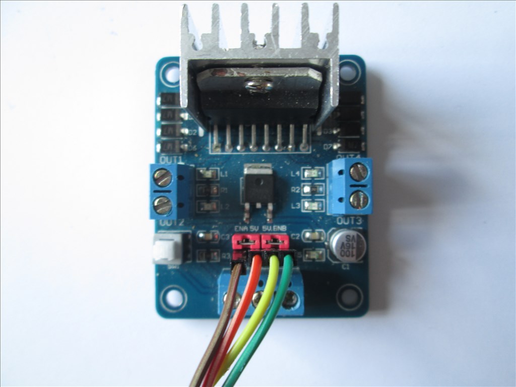
- EnA & EnB connections optional for speed control, If speed control is not required connect the two jumpers which come with the L298n to link EnA to the +5v pin to it's right and EnB to the +5v pin to it's left. If combined speed control is required (i.e. one speed control for both channels) a Y-cable can be used to connect both EnA and EnB to one Digital Port Signal (i.e. D12).
No ground or Vcc from the EZ-B to the L298n is required if you have a single source for both EZ-B and L298n or if you have a common ground.
You must make sure you press the switch to enable the on board 5V regulator circuit otherwise it will not operate
Some photos (I'll change them once I get chance to edit and tidy them up but no idea when I'll get the chance so here's the unedited ones).
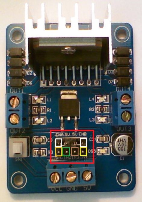
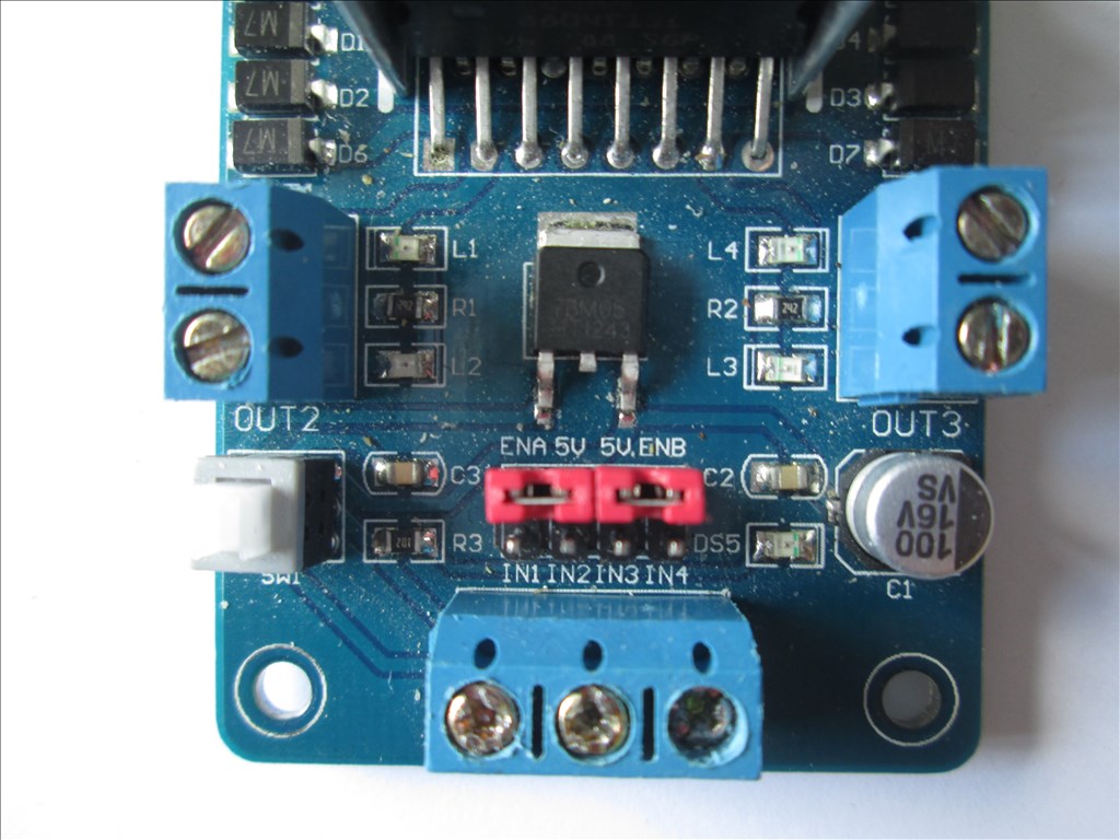
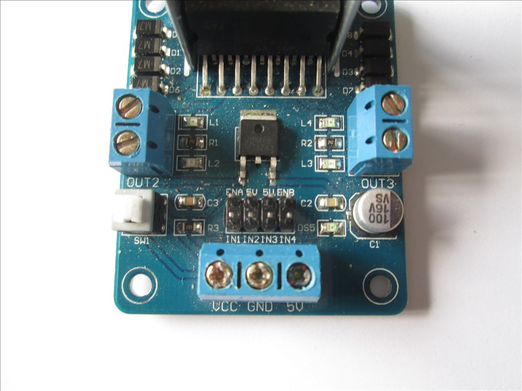
The L298n in it's stock state
The L298n wired power connections
The L298n wired for no speed control
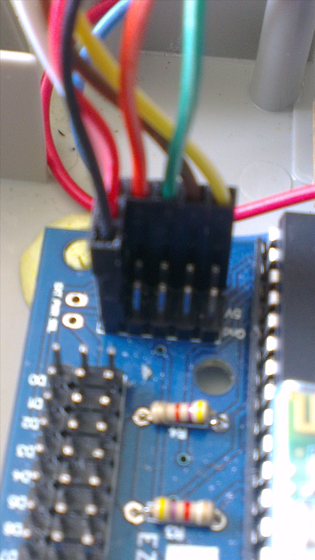
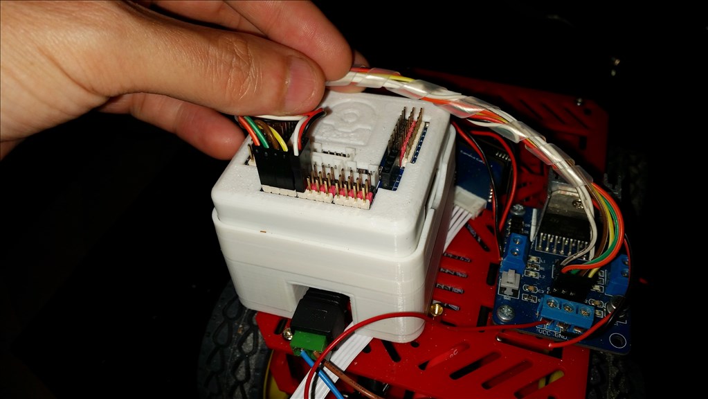
The EZ-B V4 wired for no speed control
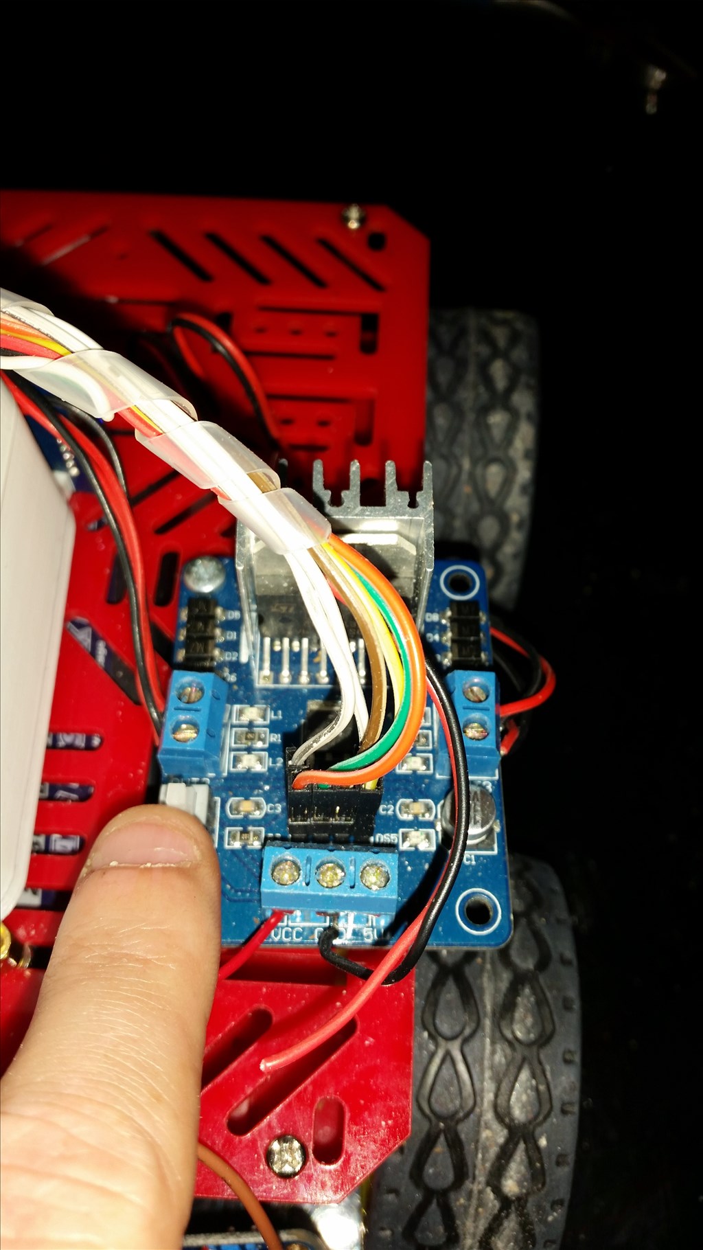
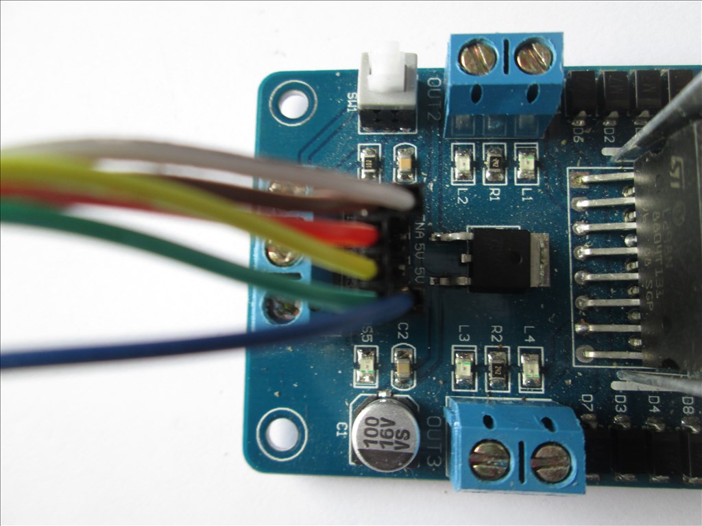
The L298n with the jumpers removed
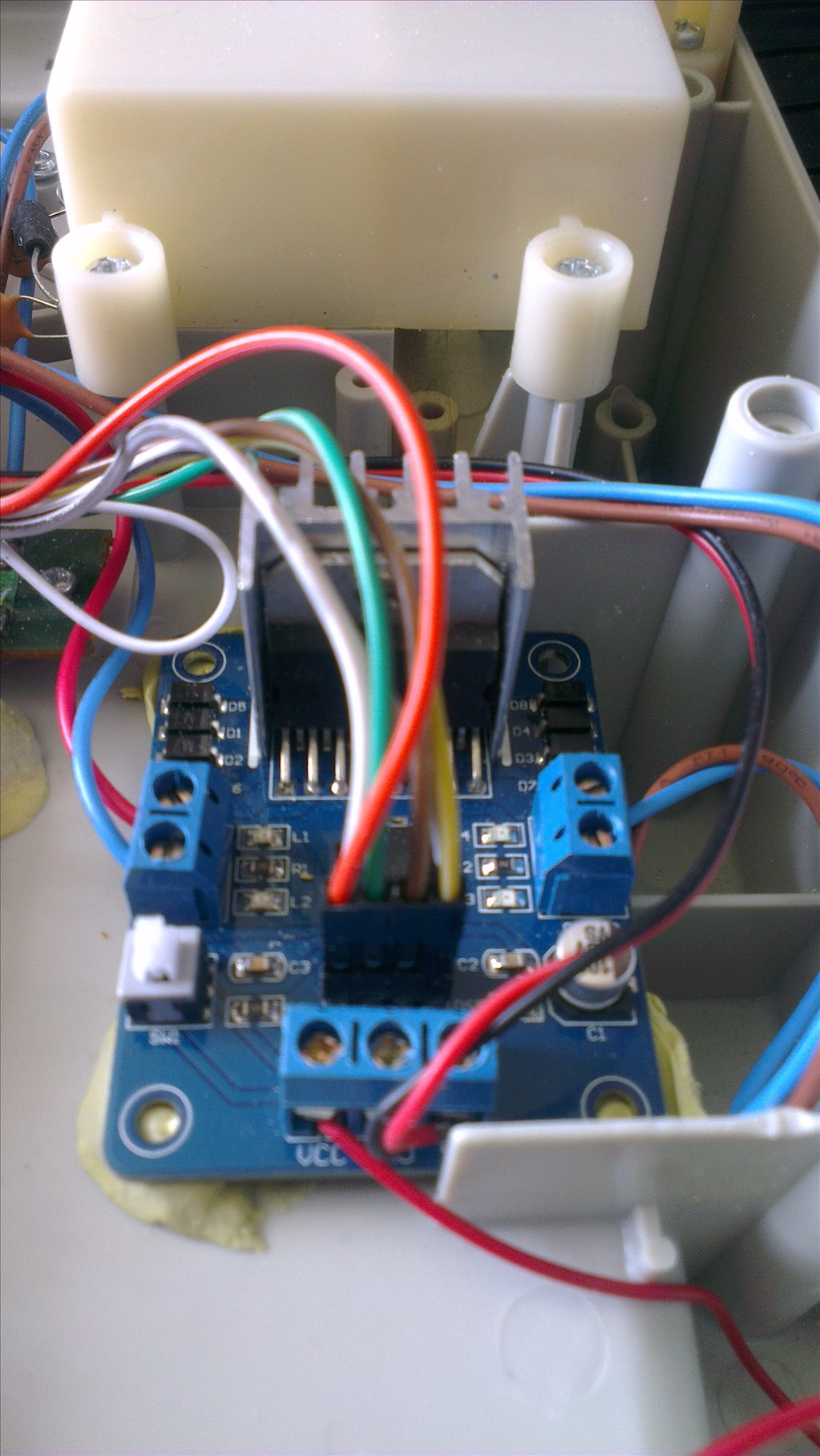
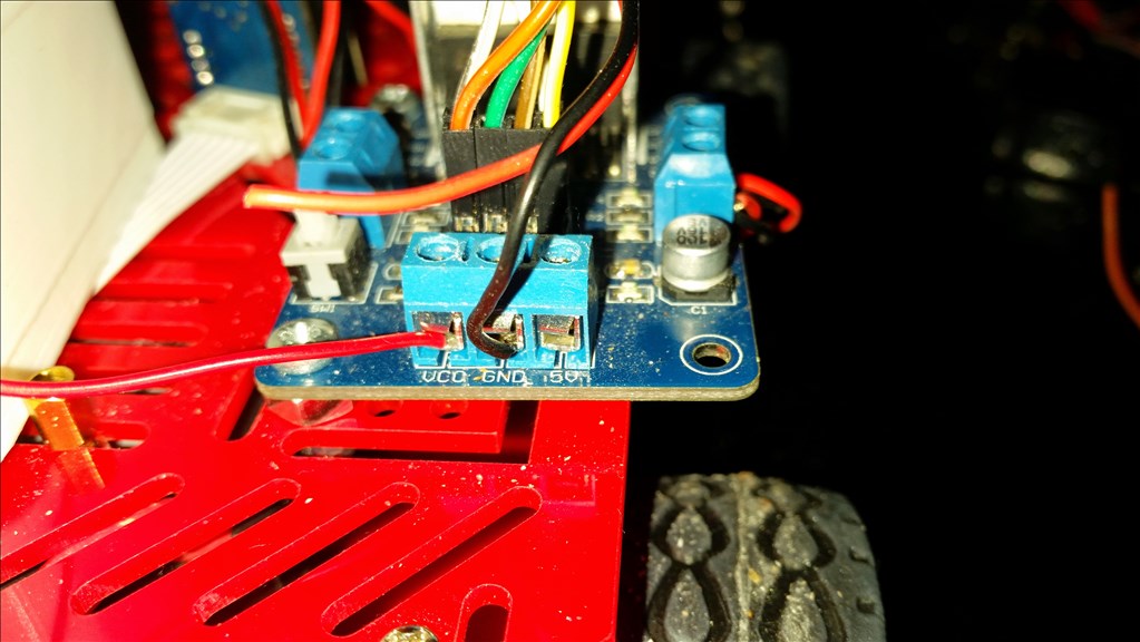
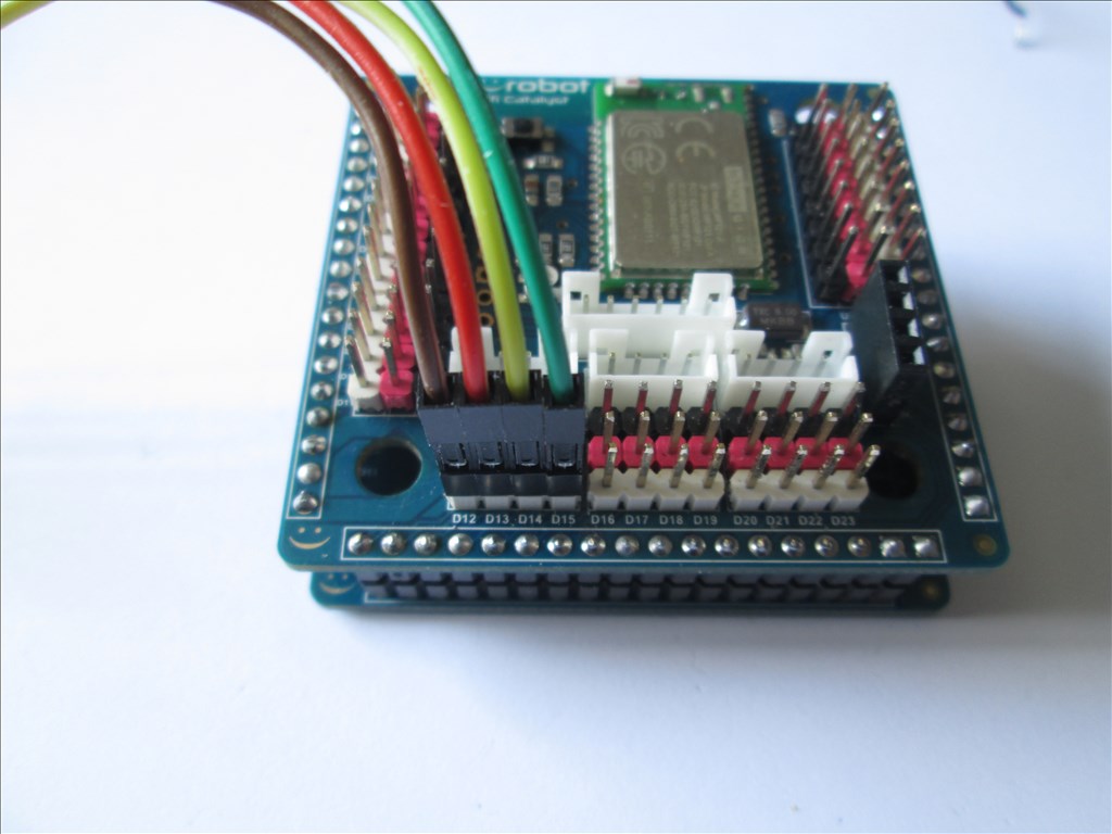
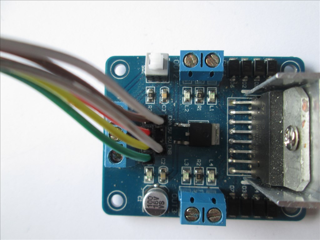
The L298n wired for common speed control (1 PWM adjusts the speed of both channels). White wires is a Y cable, 2 to 1 with the 2 at the L298n end
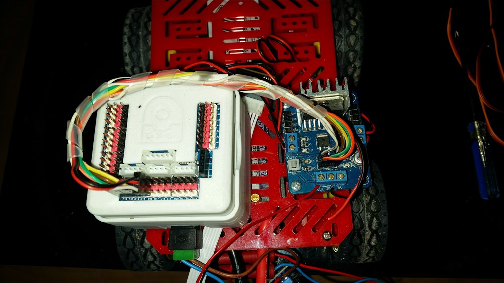
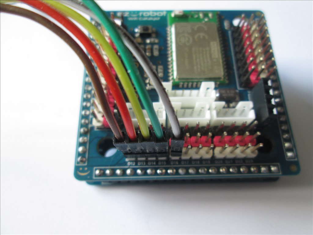
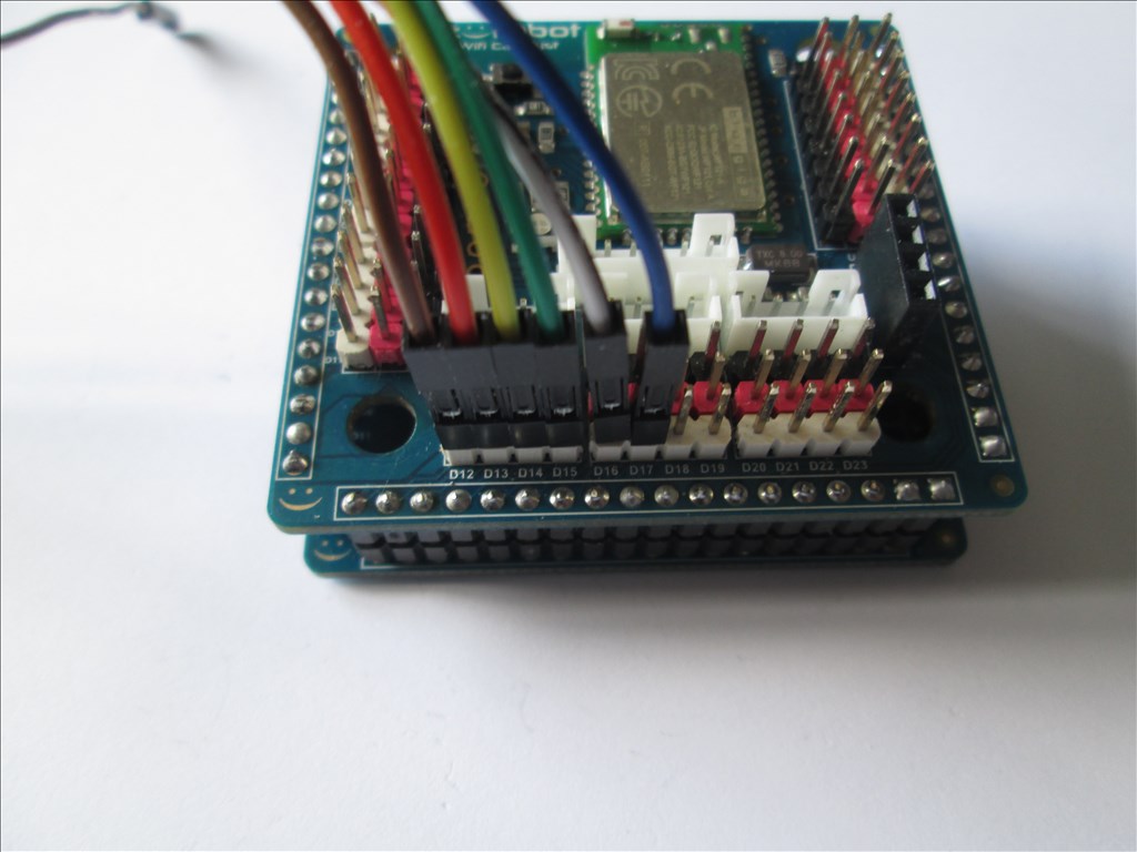
The EZ-B V4 wired for common speed control (1 PWM adjusts the speed of both channels). White wire is a Y cable, 2 to 1 with the 1 at the EZ-B V4 end
The L298n wired for independent speed control
The EZ-B V4 wired for independent speed control

@Castlehelps, you didn't mention if you had configured the HBridge to use the specified ports. Can you clarify that you indeed pressed the configure button on the HBridge and configured the correct ports?
Also, which HBridge control are you using? There are both the HBridge and HBridge PWM - each requires a different wiring configuration.
Also, are you connected to the EZ-B v4 during this test? This is done by connecting to the WiFi of the EZ-B v4 and pressing the Connect button in ARC.
Thanks! I have separate power supplies / the 12vdc is powering the h-bridge and a battery pack powers the EZ-B. So I need to wire a ground wire between the EZ-B and the ground on the H-bridge?
For DJ / I have configured the ports on the EZ-B in both configurations but no joy. Yes the computer is connected to the EZ-B.
Castle
Yep, that should be your problem. Run a ground wire between the two power supplies or the two devices.
Yes @castlephelps the ground connection from both supplies will have to be together somewhere, either on the EZ-B or otherwise. This is because both power circuits need to have the same negative reference or one value will be "floating" compared to the other value.
Also keep in mind that if you are using the H-bridge with PWM control you will need to either have an initialization script run to initiate the PWM lines (see Roli example) or you will have to move the PWM sliders once to initiate them manually.
Quick question, are you using DC motors to test with or are you still driving a stepper motor? If you are using a stepper you can't use the h-bridge controls you need a script to drive the step sequence.
Thanks! I gave up on the steppers - I couldn't get them to move either even with the code... now just a DC motor.
The ground wire trick I will be testing as soon as I get home from this Christmas party!
Castle
Yay! It works! The grounding idea was part of it and I had the PWM assigned to the wrong port...duh!
Now what I need to do is separate the two motors so that one motor does forward / reverse and the other does left and right. The reason is that I am driving a gantry for my robotic arm and one motor will move the gantry East and West and the other motor is mounted on the trolley of the gantry and will be moving North and South. I guess I just need to build a truth table that is different but I don't know how to do that. I'm so excited that it is driving my motors!
A second question is: How do I drive a motor that draws 25 Amps DC both forward and reverse As super H-bridge or ?
Castle
Glad you got the L298 sorted now.
In regards to the 25amp motors question, Dimention engineering is a popular choice. There is a Sabertooth 2x25 (not the R/C one) that delivers 25 amps per channel which can leak up to 50 amp per channel. But as you say it's only for one motor, the SyRen 25 motor driver with 45 amp peak current might be a better solution for you, although you may want to consider getting something that can handle slightly higher amperage, like the 2x32 or SyRen 50, if there's a chance you motor could draw more than 25 amps for more than a few seconds.
www.dimensionengineering.com
I believe that the SyRen 50 is the solution!
Now - if I have six motors that I want to run with H-bridges how do I do that? I am unable to add a second h-bridge to my Project in ARC?