
Zxen
I Have Just Decided To Try Replacing All My Servos With Steppers
Can someone please tell me everything I need to buy to replace my servos with stepper motors and where to buy it from? It all needs to work with the EZB-V4.
Please don't say 'it depends'. Please make the best linked suggestions for my full scale humanoid. I am currently using 9380TH servos for shoulders which has a maximum torque of 34 kg.cm (472 oz.in) (3.33 N.m) and the Torxis monster servo for the ceiling rotation plate which allows for up to 111 kg.cm (1600 oz.in) (11.3 N.m) of torque. This will probably be enough torque for those heavier joints. I don't need too much speed but obviously I need at least full human dance / martial arts speed rather than only Tai Chi speed.
I would need all the 39 motors for ceiling/base rotation plate, fingers, wrist tilt and pan, elbow tilt and pan, shoulder tilt and pan, neck tilt and pan, left waist rotation, right waist rotation, hip tilt and pan, knee tilt and pan and ankle tilt and pan. I wont worry about toes, eyes or mouth at the moment. I have seen some places to buy ugly square edged stepper motors around but not good round edged ones. Obviously square mounting or shape wont fit in most human body parts. I'll be 3D printing all the housing so the steppers need to run cool and quiet and actually fit inside their respective body parts ie. a tractor motor will not fit inside a wrist, nor will an elbow motor. An elbow pan motor might fit vertically but will it's tilt brother be able to fit horizontally? Please don't recommend steppers that are only good for sewing machines.
I don't know anything at all about how to plug these 39 steppers into the EZB-V4 (or two EZB-V4s in series link?) or how to control it all with the EZ-Robot program. Dealing with servos has taken me over a year of research so I'm hoping someone will save me that time now by giving me step by step specific product links with instructions on how to wire a stepper motor system so that it just works. With servos, I plug them into the EZ-B V4 and tell them what to do (after power has been carefully redistributed). Stepper motor control seems harder.
This is what I know I need:
- the stepper motors
- at least one high current power supply
- at least one EZB-V4
I don't know anything else at all about the electronic products needed, wires needed, tiltpan systems available, housing options, etc so if you use words that laypeople don't know, I probably won't know them either. Your answer will help anyone looking to play with steppers after using servos, so please give clear instructions with trustworthy links and prices (American dollar prices will be fine even though I'm not American). Thanks so much in advance on behalf of everyone on the entire internet who ever googles how to move from servos to steppers. Most stepper information on the internet requires pre-requisite information and is vague, so the most valuable thing here is the links to the specific best choice products, their prices and how they wire together. Thanks again

Here's a good start: https://synthiam.com/Community/Forum/Search?query=Stepper&page=1
To see what many others have done - should prevent much trial and error. I don't have any experience, but all those people do. Should find something useful in there
Thank you. Looks like nobody has really solved this neatly yet. I am interested in steppers because I heard that they remain stiff after the power is shut off, unlike servo robots whose arms come crashing down to break everything the moment you switch off your robot. Do stepper motors really have this default locking attribute? Remote control skateboard motors auto-brake somehow as well. Also, the shafts are centred on steppers, meaning no more centralising with an artificial shaft :):):) On the other hand, the manufacturers provide a shiny bald shaft by default that requires you to clumsily squeeze something around it lest everything slip off. Also, steppers don't need alignment during installation. They're in their starting position no matter what. Maybe I need to convert my servos to continuous rotation for this benefit. The other option is fast linear actuators (rare, slow, expensive, oversized and generally incompatible with servos) - but this would only work for tilt, not pan. For braking I've conducted hundreds of experiments with solenoids, springs and micro servos to create holding brakes but my apartment isn't exactly a lab so I've put that on 'hold' for the moment. Thoughts?
The power to the stepper needs to be maintained to hold position. I believe the current required to hold position it determined by the rotational load being applied. The more load applied, the more current needed to maintain position. As Richard R said, the gear drive system helps determine if the position is held ( worm gear type reduction is automatically locking). I never heard them to hold position without power applied. Ron
One of my old braking ideas with a servo was to create a sparsely threaded worm rather than a threaded worm with many spirals per centimetre. I mean, think of the peg winding mechanism on the head of a guitar - the worm drives there have around 5 rotations per centimetre. But what if we brought that number down to one or less? I was never able to figure out the maths of the shaft gear diameter and number of teeth to worm spiral ratio, though. The worm drive can only be turned from the pinion gear- the worm itself is locked if the pinion is not moving. So if the worm cylinder is bearing the weight of something, it is braked at all times by default. A steep or obtuse spiral thread would bring the speed of a linear actuator up much higher if this were created. Linear actuators are often around 14 times slower (14:1 ratio) than the pinion (shaft gear of a servo). If anyone is good at maths, can you please make everyone a fast linear actuator from a standard hobby servo so we can all have the brakes that servo manufacturers can't be bothered installing by default? I'm willing to sacrifice some speed for a holding brake. Its not ideal, but its free, and it will be faster than any other linear actuator on the market.
Then add another spur gear, but this time centre the shaft. This will result in the original direction of rotation and we will have created both a holding brake (a basic one that costs speed but improves torque) and a centred shaft. Please put the final cog on the wide side of the servo motor. Then encase the whole thing in a cylinder. If you've done all that you might as well keep the wiring on the inside and just have a PWM port. You should cut off the mounting tabs first, then print the indentation in the design to secure it. Standard hobby servos are around 20x38x41mm, from memory. Cutting off the tabs will result in the lowest possible diameter.
These are the only gears I know of that fit onto Hitec splines directly https://www.servocity.com/html/servo_mount_gears.html. They may have too many teeth for a steep spiral thread but they will help you get started. If you know anyone who custom makes metal gears cheaply, please let me know too.
I don't know of a motor that "locks"'position. The only reason one would appear to "lock" when power is removed is due to extremely high gearing. Some real cheap servos will have a greater "locking" appearance because they have uneffecient plastic gears without ball bearings - but that would reduce the lifting strength and use a great deal more energy to move. Also the "locking" wouldn't be dependable.
I thunk what you're looking for is some kind of locking mechanism that can be attached to the gear, like a winch. For every click of the gear, a spring can push a tooth into a gear. But that would only work one way. Unless you devised an electromagnetic coil to hold it.
Either way, you are inventing something new. It can be done - it'd start by getting a 3D printer
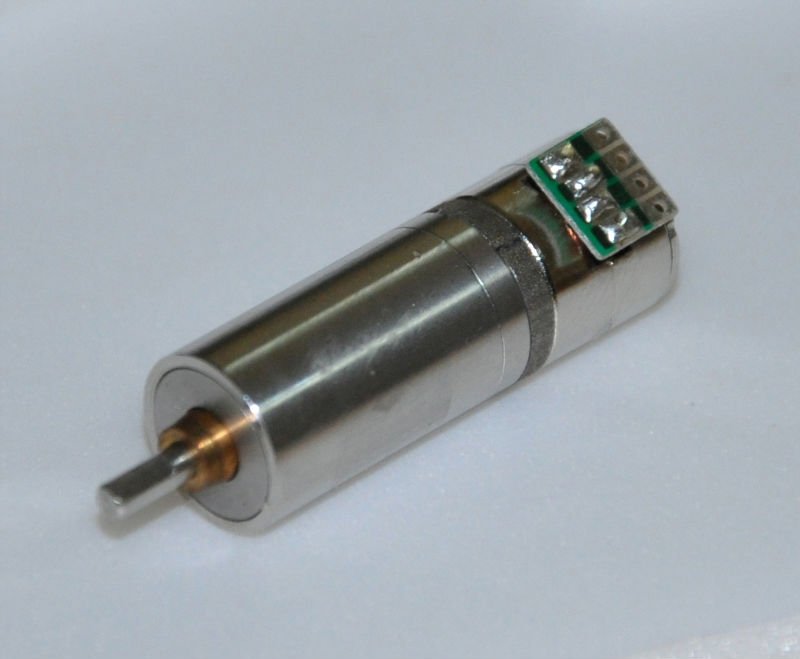
I will take one of the "servos" apart that I use and send a photo. The "Servo" has no controller in it so you would have to control it from some other device. It will give you a good idea of how to incorporate the gearing to allow the "lock" to happen. These hold position with very little current and are extremely silent. Give me a couple of minutes to get a photo out.