
Zxen
I Have Just Decided To Try Replacing All My Servos With Steppers
Can someone please tell me everything I need to buy to replace my servos with stepper motors and where to buy it from? It all needs to work with the EZB-V4.
Please don't say 'it depends'. Please make the best linked suggestions for my full scale humanoid. I am currently using 9380TH servos for shoulders which has a maximum torque of 34 kg.cm (472 oz.in) (3.33 N.m) and the Torxis monster servo for the ceiling rotation plate which allows for up to 111 kg.cm (1600 oz.in) (11.3 N.m) of torque. This will probably be enough torque for those heavier joints. I don't need too much speed but obviously I need at least full human dance / martial arts speed rather than only Tai Chi speed.
I would need all the 39 motors for ceiling/base rotation plate, fingers, wrist tilt and pan, elbow tilt and pan, shoulder tilt and pan, neck tilt and pan, left waist rotation, right waist rotation, hip tilt and pan, knee tilt and pan and ankle tilt and pan. I wont worry about toes, eyes or mouth at the moment. I have seen some places to buy ugly square edged stepper motors around but not good round edged ones. Obviously square mounting or shape wont fit in most human body parts. I'll be 3D printing all the housing so the steppers need to run cool and quiet and actually fit inside their respective body parts ie. a tractor motor will not fit inside a wrist, nor will an elbow motor. An elbow pan motor might fit vertically but will it's tilt brother be able to fit horizontally? Please don't recommend steppers that are only good for sewing machines.
I don't know anything at all about how to plug these 39 steppers into the EZB-V4 (or two EZB-V4s in series link?) or how to control it all with the EZ-Robot program. Dealing with servos has taken me over a year of research so I'm hoping someone will save me that time now by giving me step by step specific product links with instructions on how to wire a stepper motor system so that it just works. With servos, I plug them into the EZ-B V4 and tell them what to do (after power has been carefully redistributed). Stepper motor control seems harder.
This is what I know I need:
- the stepper motors
- at least one high current power supply
- at least one EZB-V4
I don't know anything else at all about the electronic products needed, wires needed, tiltpan systems available, housing options, etc so if you use words that laypeople don't know, I probably won't know them either. Your answer will help anyone looking to play with steppers after using servos, so please give clear instructions with trustworthy links and prices (American dollar prices will be fine even though I'm not American). Thanks so much in advance on behalf of everyone on the entire internet who ever googles how to move from servos to steppers. Most stepper information on the internet requires pre-requisite information and is vague, so the most valuable thing here is the links to the specific best choice products, their prices and how they wire together. Thanks again

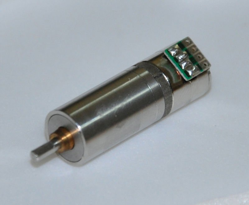
I believe this is similar to what you had described above. These are the ones Toymaker also uses. Its not a great form factor unless you are designing your own robot, but if you are, they work quite well.
What control device will tell the motor stepper driver to move? This controller should also be able to operate an electromagnetic brake. A solenoid commonly used on paper printers for feeding, could be used to release a mechanical gear brake. These solenoids can develop a reasonable amount of power. Using a pawl against a spur gear on the motor shaft, held by a spring, could allow quite a bit of holding power.
I know this makes things a bit more complex but if you don't want to use a worm gear drive (keeping it simple) this may be a way to accomplish what you want.
Just another thought.
Ron
CochranRobotics, what kind of motor is that? It appears to have a lock
Andy Roid, I already know (after a lot of effort) two ways to activate an off-brake at exactly the same time an individual servo moves in such a way that a servo's non-movement reapplies the brake. Linear actuators that I've found nearly always have a shallow spiral and are therefore extremely slow.
The 2 methods I have figured out to build an electronic holding brake (rather than a spiral worm holding brake) are described below.
Let me first say that I spent weeks messing around with soldering these RC switches from pololu (not recommended) https://www.pololu.com/product/2803 and some RC switches like these (this kind is fine for switching LEDs and solenoids ON without any fade capabilities - they just stay turned off until rotation reaches something like 90 degrees clockwise rotation - which is fine if you want to switch a non-PWM device such as an LED on using a PWM input) https://www.ebay.com.au/itm/like/261684396842?lpid=107&chn=ps. I spent ages on it.
I racked my brain to figure out how to simply make the solenoid (a little pushing pin in a magnetic coil with a spring like this https://www.ebay.com/itm/2pcs-DC3-12V-Push-Pull-Type-Solenoid-Electromagnet-DC-Micro-Solenoid-ACM-/361406950245) pull away from the wall the very instant the servo was given a pulse using RC switches. Solenoids theoretically would be the correct braking mechanism, but they are extremely weak when they are small. The magnetic strength depends on the number of coils of insulated copper and the current that pulls the pin against the spring. I even bought rolls of insulated copper wire to try to make them myself. That was a nightmare.
I originally used teeth in a rotation wall around the servo that the solenoid pin could lock into, but it takes more power to pull past a tooth than I thought. Then I decided that the the solenoid should friction-press with a rubber stopper like a drum brake instead. The problems were twofold: The magnet couldn't be strong at hobby servo scale and so the spring couldn't be strong. But... to save all of hobbykind from the torment of dealing with RC switches that only activate after 90 degrees rotation etc, I will tell you how to INSTANTLY activate a device the EXACT moment the servo receives a pulse. This means I also solved the LED fading issue as well: Ready? This took me ages. But its bloody obvious after you hear it. This is how to activate an off-brake/holding-brake the moment the servo receives a pulse:
Attach the device to the wires of the DC motor inside the servo!
After all, the motor only receives a signal when the electronics in the servo tell it to move. So there's that massive problem solved. I advise anyone wanting to build robotic switches to contemplate hacking servos before you search google for 7 years reduced lifespan worth of stress. (That's how I measure the ease of a google search - by the length of time it will take off my life to find the solution).
Bear in mind that the brake will only release as gradually as the speed of the servo motor if you solder the off-brake solenoid to the DC motor inside the servo, but at least its both instantaneous and compact. A servo manufacturer could tweak this idea into a single servo with attachable brake as a single product. I was going to, but I'm broke.
So I've mentioned the mechanical gearing solution using a standard hobby servo with a low thread count worm drive as a holding brake system. I've mentioned solenoid 'electropin and spring' holding brakes activated from the servo's motor. I've mentioned the powered auto-brakes used in remote control skateboards (more research required). Now I'm going to tell you something similar to the solenoid but more controllable.
A servo-spring holding brake. This is not an automatic brake and takes up quite a lot of space, requires brake-release programming, and will probably double the size of your robot. But its the only reliable thing I have figured out to reliably work. Simply allocate a nano servo (if its strong enough) to every servo in your robot and set up a spring that forces a rubber stopper into the housing wall of your tilt or pan segment. Then program the nano servo to release at the same time as your movement servo wants to move. You need to program the nano to push back to brake, even though the spring will do that automatically when power is cut. This will reduce jitter in all robots, allow them to hold their poses using minimal power, and stay in position when power is cut. I wasn't going to tell anybody because I wanted to build it first then show people, but I think a lot of you guys have built a lot of advanced stuff and will actually help me out by refining a brake that I could use. Anyway, there's the main answer to hundreds of hours of unpaid research.
I hope one of you builds a one-size-fits-all holding brake solution for standard sized hobby servos that is upscalable for stronger holding power. The whole effort is in making it compact. Also, I highly recommend friction grip rather than teeth for several reasons.
look at automotive motors used for climate control door flaps. These are Bosch ones for Audi's, but other manufacturers may also work for you.
I have tried to find a video to see how fast these blend door actuators move and how loud they are, and what wiring is required to move them in either direction. I assume I can connect one to the motor terminals inside a servo and control them with the EZ-Robot program if the voltage is the same. Its a pity they're so large - too big for most of my projects, but exciting to know the engineering to brake a motor has already been devised. Do you have a video that shows maximum speed and noise? If its only as fast as a standard linear actuator then there's unfortunately no benefit to using them. They look slow because the spiral thread count on the worm gear is high.
Edit: I just looked at your first comment and read that you mentioned toy actuators. Here is a toy that is very small and still works fast:
https://www.youtube.com/watch?v=VWRgi4uuxEU
https://www.youtube.com/watch?v=xoLxWgtntjE
Arms up and down, and neck left and right are using these motors.
Fantastic design, David. Did you use a 3D printer for the housing? Also, why didn't you choose servos - was it because you wanted brakes or were they less noisy? How small are your motors? Where did you get them from? What is causing the head to wobble?
https://plus.google.com/u/0/communities/115080096051481641499 has many of the answers you are looking for.
I wanted positional information back from these motors. This is important in the design as the arms need to be in a certain position to pocket themselves. The motors are very strong and durable. I also wanted motors that draw very low current and are silent. The "locking" type design was also desirable.
The motors are about 2"x2"x1" or about 5cmx5cmx2.5cm without the mounting holes in the 3 corners or the housing around the plug in.
Ebay has these motors. You can get after market ones but they normally have plastic gears for the worm gear which I don't like. They strip out in time.
https://www.ebay.com/itm/AUDI-A6-HEATER-AIR-VENT-FLAP-MOTOR-REGULATOR-0-132-801-129-4B1-820-511-C-/272163433606?hash=item3f5e346c86:g:WnYAAOSwwpdW4Oos&vxp=mtr is an example of one of the motors on ebay. These run at 12v to 24v. I run mine at 12v.
On the head wobble, the video shows the first design. This was using one of these motors mentioned for head up/down movement. There was too much weight in the front of the head in this design for this motor. It worked but needed springs to make it wobble less. I have since redesigned this to use an actuator motor for the up and down movement of the head, which eliminated the wobble.
The movement on this one is very loud (robot moving forward and such) due to me using a ball caster. This has been removed with an omni-direction wheel to make it much quieter.