Asked — Edited

How Do I Use A Servo Control Board To Operate A Linear Actuator?

Hi All,

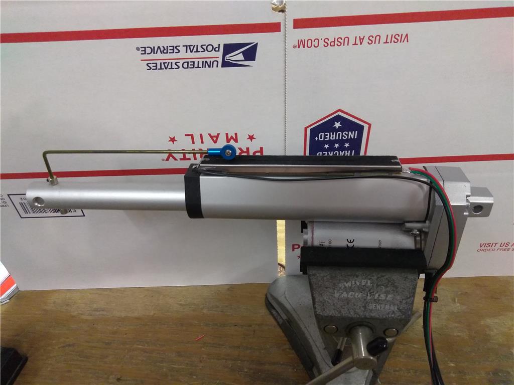
if you are using a 12vdc linear actuator without feedback and you use a servo control board (6v - 7.2v) with a pot connected to the actuator for feedback, where would the linear actuator's 12v leads connect to being the motor outputs of the servo control board are a lower voltage?

Would you also have to have an H-bridge connected to the servo control board?

Thanx.


ARC Pro

Upgrade to ARC Pro

Unlock the true power of automation and robotics by becoming a proud subscriber of Synthiam ARC Pro.

#1  

I don't think you can't use a generic hobby servo control board for that actuator. I doubt it could provide enough current (not to mention volts) to move the actuator. You will still need some type of larger motor controller (i.e. H-bridge) in order to control the direction of the actuator (or motor).. The role of the pot is to give position feedback. The H-bridge will control direction...

This is how it would work... You connect the actuator to the H-bridge, The ezb4 would control the H-bridge. The pot would be connected to the ezb4 analog port. With some scripting you can read the pot for position status then control h-bridge for position and direction...

#2  

Thanx Richard. Like you said, I figured I would need to use a higher voltage/current controller.

Would you by chance have an example script similar to how I need to write for my situation?

Thanx again.

PRO
Synthiam
#3  

A better solution is...

  1. Purchase an HDD servo HDD Servo

  2. Remove the PCB and Pot. Disconnect the motor wires

  3. Connect the PCB's motor wires to your own motor

  4. Add the pot where ever it can be measured in your application. Or use a new pot if your actuator already has one built in.

  5. Connect the servo to your EZ-B v4/2 Wi-Fi Robot Controller or EZ-B IoTiny

  6. Use absolutely any control in ARC that supports servos... including Auto Position gait creator, camera tracking, WiiMote, mobile apps, etc...

PRO
USA
#4  

@DJ,

Quote:

if you are using a 12vdc linear actuator without feedback

Is the HDD servo PCB compatible with a 12v motor ?

PRO
Synthiam
#5  

Yeah - the specs of the mosfets are actually quite high. Jeremie can chime in on that.

PRO
USA
#6  

@DJ,

That is very interesting :)

@Jeremie,

More details please: i.e. max amps @ 12v

PRO
Canada
#7  

hello, i am jeremie. I don't log out of public computers. :D

*Edit: I'm logged out now, thanks @DJ :D

PRO
Synthiam
#8  

Hahaha.... so PTP, jeremie says the mosfet is rated for 16 volts, or something in the servo... BUT, the voltage regulator for the rest of the electronics might not be that high (maybe 8.4v). He's going to check first to verify.

The thing is, a 12v motor can still run decently off 8.4 volts, it'll just draw more amps

#9  

I see what you guys are saying, but how do I get 12vdc from the servo control board if my EZ-B is only powered by 6vdc?

The other issue is that if I were to use the lower voltage from the EZ-B to the servo control board like DJ said, the motor would definitely draw more amperage, but I believe the motor would also run much slower.

#10  

@Rob-bot You need two separate power sources or a step down power converter to take 12v to 6V This is how you do it... 12v connects to the servo board and 6V connects to the ezb4... make sure you have common grounds between them

Do you need 6v for anything (like regular servos) because the ezb4 will happily work with 12v?

PRO
Synthiam
#11  

Like Richard said. You only need 6v if you’re using components that require 6 volts, like servos.

If you need 12v and 6v then have two power sources. Share the same ground.

Lastly, if you’re worried about the motor moving too slow at 6v then I would simply connect an hbridge to the servo pcb motor wires. Power the servo pcb by 6 volts and the hbridge by 12.

The servo pcb will be controlling the polarity of the two output wires that also controls the input of the hbridge.

#12  

"12v connects to the servo board"

Richard, your saying I can put 12v straight into the servo board?

"Lastly, if you’re worried about the motor moving too slow at 6v then I would simply connect an hbridge to the servo pcb motor wires. Power the servo pcb by 6 volts and the hbridge by 12. "

"The servo pcb will be controlling the polarity of the two output wires that also controls the input of the hbridge."

DJ, I see your point. Which inputs should I put the servo PCB motor wires to, on the hbridge?

PRO
Canada
#13  

@Rob-bot

I got word from our manufacturer, 8.4V is the maximum voltage the HDD servo electronics can operate at. 12V is too much.

#14  

Thanx for clarifying Jeremie. That was what I thought, but I think I confused Richard.

So, I think my only choice is to wire the service PCB to Hbridge, like DJ said.

I just need to know which inputs I should use on the Hbridge.

#15  

So, this is the easiest/cheapest solution I came up with to making feedback on a linear actuator...

I siliconed a 100mm 10k slide potentiometer ($3 ebay) to the flat side of a 100mm common linear actuator ($30) and drilled a small 3mm hole through the top end of the shaft at the closest part that is exposed when the shaft is retracted inside the body and used a 90 degree bent piece of wire coat hanger with small 3mm shaft collars ($1 ebay) to keep it from coming out and drilled a 3mm hole through potentiometer slider tab and using 2 part epoxy, I added a 3mm ball joint ($2 ebay) to the other end of the wire coat hanger and screwed it to the slider tab with a 3mm machine screw and nut with some liquid thread lock to keep the nut from loosening.

It gives perfect feedback to add to a servo control board and/or hbridge to use as a linear servo to connect to your EZ-B without paying over $130 for one.

User-inserted image

#16  

I believe you can now buy those with built in feedback ability.

#17  

"I believe you can now buy those with built in feedback ability."

You can, but for the price of 1 you can build 4.

United Kingdom
#18  

@Rob-bot, pretty neat ldea, simplistic but looks very effective! A great idea.

It has given me an idea of using this, I assume 100mm ( 4 ) is the largest linear slider pot you can get? I’m based in the UK and can only find up to 100mm.

Also where did you get the linear actuator for $30?

#19  

"@Rob-bot, pretty neat ldea, simplistic but looks very effective! A great idea."

Thanx

"It has given me an idea of using this, I assume 100mm ( 4 ) is the largest linear slider pot you can get? I’m based in the UK and can only find up to 100mm."

I think 100mm is the largest I’ve seen and I've also seen them in 75mm, and 50mm, so, you can use them for 3" and 2" actuators too.

"Also where did you get the linear actuator for $30?"

I get them on ebay.

PRO
USA
#20  

@Rob-bot,

Did you managed to get the solution i.e. (Servo/PCB + H-Bridge + DC Motor + Potentiometer) and get it working ?

I replicate the solution using a car windshield 12v Bosch Motor (Toymaker post) and all the other stuff.

if you need I can make a video.

#21  

Hey folks,

I'm trying to connect a L12 option R linear servo by Actutronix to an L293D h-bridge chip to drive the actuator back and forth, but I'm having trouble deciding how to set it up.

The linear servo only has 3 wires unlike a DC motor with only 2 or stepper with 4. So I was curious if anybody had any ideas on how to configure the actuator. I have attached data sheets for both mentioned parts.

Thank you!

hbridge.pdf

ActuonixL12Datasheet.pdf

#22  

WIRING: (see last page for pin numbering) 1 - White RC input signal (RC-servo compatible) 2 - Red Power (+6 VDC) 3 - Black Ground

PRO
USA
#23  

@Handy Dandy,

If you have the option R, Dave's post is correct.

Quote:

The R actuators or linear servos’ are a direct replacement for regular radio controlled hobby servos. The desired actuator position is input to the actuator on lead 1 as a positive 5 Volt pulse width signal. A 1.0 ms pulse commands the controller to fully retract the actuator, and a 2.0 ms pulse signals it to fully extend. If the motion of the actuator, or of other servos in your system, seems erratic, place a 14O resistor in series with the actuator’s red V+ lead wire.

basically what you have is a Linear Servo.

You can't use a H-Bridge, you will need a micro-controller to pulse a PWM signal between 1000us (Retracted) and 2000us (extended).

#24  

"Did you managed to get the solution i.e. (Servo/PCB + H-Bridge + DC Motor + Potentiometer) and get it working ?

I replicate the solution using a car windshield 12v Bosch Motor (Toymaker post) and all the other stuff.

if you need I can make a video. "

ptp,

that would be great if you can post a demo video. Please let me know if you do as I have not had the chance to try the components out yet and would rather start off connecting them properly. :D

#25  

IJust an FYI for those interested. I did find a 10k slide pot that is 128mm (5" ) long on eBay, which means you can go up to a 5" linear actuator. Although 5" linear actuators are not common, they do exist, plus you can always take a 6" actuator and internally adjust the limit switch to 5" if needed.

United Kingdom
#26  

Thanks Rob-bot!