Asked — Edited
Resolved Resolved by Dunning-Kruger!

H Bridge Reverse Instead Of Backing Up

This is bugging the hell out of me...I have a L298N H bridge setup and for the life of me cant seem to figure out why Megabyte turns to the right . Instead of reversing straight back! Ive tried swapping all the combos for movement in EZ builder. Forward, left and right work. But reverse he seems to pull to one side. Im sure its something obvious,...but im stumped!


ARC Pro

Upgrade to ARC Pro

With ARC Pro, your robot is not just a machine; it's your creative partner in the journey of technological exploration.

#1  

Hey , i have had the same problem before. You can either reverse polarity on the motors connections or swap the enable pin connections. One of them is backwards. I tried 4 times before i had it all moving in the correct direction lol ,

You can swap around the connections in the Movement Panel all you want but if one side is wired backwards it will turn instead of reversing straight back.

#2  

Sorry, nothing to add... just misread your post... As Josh said, trying swapping wires....

United Kingdom
#3  

Check out my H-Bridge tutorial, it should explain why it is doing what it's doing and tell you how to fix the problem.

#4  

User-inserted image

Flipped the wires and still nothing baffled. I pinned it out using Richs guide and it worked before o started cleaning up wires

United Kingdom
#5  

Do you have the enable (EnA and EnB) supplied with +5V or a PWM? One signal to each of the Ins (In1, In2, In3, In4)? +5V to the +5V? Or the switch pressed for on board regulation (if your board has that option)? Voltage for the motors also plus a common ground?

If so it should work provided the Enables are high and the In1 to In4 have the correct High/Low to make the motor move.

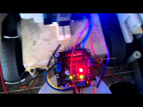
Pay careful attention to the labels on the L298N board, there are a number of variations, yours looks different to mine.

#6  

EnA and EbB are wired togther with a y cable . They run to D0 for PWM. IN1,IN2,IN3,IN4 run to D16,D17,D18,D19.

United Kingdom
#7  

Make sure you have PWM or a digital On set for D0 (otherwise it wont work).

Then, provided D16-D19 are on In1-In4 in the same order it should just be a case of setting the H-Bridge control to D16 down to D19 in order. One motor (or both) may run the wrong way due to polarity of the motors, if that's the case swap D16 with D17 in the control and/or D18 with D19.

Provided you have D0 giving EnA and EnB +5V or a PWM the control should at least do something.

If it doesn't work test all wires from EZ-B to H-Bridge for continuity, make sure there isn't a break in one of them.

If it still doesn't work take some jumper wires and carefully connect up from the Vcc (i.e. +5V - I assume this is a V3 you are using, don't do this with a V4) like so;

Vcc to EnA Vcc to In1 Ground to In2 Does motor 1 spin?

Then Vcc to EnB Vcc to In3 Ground to In4 Does motor 2 spin?

That should check if the H-Bridge and motors are working. If nothing happens then there is an issue with the H-Bridge or the motor. If that is the case, eliminate the motor from being the problem and just provide it with a Vcc and Ground to check it spins. If it does then the H-Bridge has an issue. If it doesn't then the motor is toast.

#8  

User-inserted image

@ Rich this is the board im using. Will it make any difference when trying to trouble shoot? The motors turn and i can see the lights on the bridge come up. But i still cant get it to reverse. If i do get it to reverse it wont move forward. Tried swapping jumpers and there good

United Kingdom
#9  

The boards are basically all the same just some have LEDs some don't, some have different layouts, some have on board regulators but fundamentally they are all the same, the L298n chip is the same so it will work the same way.

If the lights come on that's a good thing, this will tell you if it's set up correctly or what is happening at least.

There should be 2 LEDs per motor. One LED indicates forwards movement, the other indicates backwards movement. The same for the other side.

What do the LEDs show when you try and make it move forwards and reverse? Does each side show an LED lit up? And if doing the other direction do the other two light up instead?

Does it not move at all when you try to reverse? Have you tried it with the +5v to EnA and +5v to EnB jumpers attached and no PWM for speed control (keeping those jumpers on will make it run at full speed always and removes the requirement for PWM)? Does it turn OK?

Your H-Bridge doesn't seem to have a switch but looks like it has a regulator. Is the jumper that's on it's own in the middle of the board control the on board regulator? You can use it with or without but if you use it with the regulator you don't need the +5V to the screw terminals. Doing so will provide a back feed to the EZ-B, I don't think it will damage it but it's safer not to connect it.

#10  

The leds indicating which side is running always seemed to be crossed. So In2 and In3 will light up on reverse . In2 and In4 will light up when going forward so straight across from each. I'm at work now so going off memory . Might have to make a video if I can't figure it out later

United Kingdom
#11  

A video would help see what's happening.

Here are some images to help show how it should be wired (however I believe it is wired OK)

First remove these jumpers (indicated in red) User-inserted image

This should expose these required pins (indicated in green) User-inserted image

The run the wires from the EZ-B and battery as shown (note ground can come from either the battery or the EZ-B, I prefer to take it from the battery however have done both methods, it makes no difference really) User-inserted image

Where digital ports are specified this means the Signal.

In1 - Orange to D16 Signal In2 - Yellow to D17 Signal In3 - Cyan to D18 Signal In4 - Magenta to D19 Signal EnA & EnB - Grey to D0 Signal +5V - Pinkish Red to any digital port Vcc (if required) Vcc - Red to Battery positive Gnd - Black to Battery ground (or any digital port ground)

Then connect the motors to the 2 motor outputs. Either way around it doesn't make much difference and can be corrected in the config.

In ARC set up the H-Bridge Control like this; User-inserted image

Or like this with a PWM control User-inserted image

User-inserted image

Slide either the PWM to 100% or the speed controls on the H-Bridge with PWM to 100% for both

Move the robot.

If it turns left when set to move forwards your left motor is running backwards, either reverse the polarity on the H-Bridge itself or swap over the ports in the control (depending on which motor is connected to which side will determine which ports to swap)

If it turns right when set to move forwards your right motor is running backwards, reverse the polarity of it on the H-Bridge or swap the ports in the control, same note as before.

If it moves in reverse when set to move forward both motors are running backwards, reverse the polarity or swap over the ports in the config for both pairs (i.e. swap D16 for D17, D17 for D16, D18 for D19 and D19 for D18)

The full list of what to change if it doesn't act correctly is in my tutorial previously linked to. If it is doing something that I didn't list in it then a video will be needed really.

United Kingdom
#12  

I just noticed after all of that that In4 and In3 are the other way around to what I thought. It doesn't matter really but it's not quite right. Cyan and Magenta just need swapping over on the port numbers and my description.

United Kingdom
#14  

Forgive me if this is a bit brief, I'm tired and just come back from a few days away where I had very little sleep so my brain isn't what it usually is.

It's wired correctly. For some reason though on some directions the H-Bridge is acting like it isn't getting a signal. You should be getting 2 green lights for each of the movement directions. For two of them you are getting only one green light.

Basically, check those green lights when you run the directions. If one of them never comes on then it's likely a problem with the wire or that connection on the H-Bridge.

Say a 0 is a light off and 1 is a light on, it should follow this pattern;

Forward

1 1
0 0

Reverse

0 0
1 1

Left

1 0
0 1

Right

0 1
1 0

Or something similar to that. In each case you should have one green light on each side of the H-Bridge light up. If any of the lights never light up then check the wire going to that In connection on the H-Bridge.

If the wires are all OK it could be the H-Bridge which is faulty. I could guide you through testing continuity between the In pins and the chip however check the LEDs and the wires first, by which time I should have had some sleep.

PRO
Canada
#15  

Hi @Xuven

I'm with @Rich I believe one of your input signals isn't reaching the H-bridge from the EZ-B. Replace the jumper wires on D4 and D5 with new ones (I know it's one of them but I don't know exactly which one). The green LEDs should both always be lit up when direction signals are sent to the H-bridge. Thanks for the video it definitely helps in troubleshooting the issue!

#16  

@Rich Thanks for all the help. I have tested all the jumpers with a toner to test for breaks and shorts. So far everything is good. At this point im going to assume its the H Bridge and replace it.

#17  

I got credit for resolving this and I shouldn't have... I think @Xuven meant this for Rich.... If EZ Robot can, they should debit me and credit Rich.....

United Kingdom
#18  

Don't worry about it dude, I'm sure I can afford to let a few slide and I'm sure I've been credited where you should have been a few times in the past too.

@xuven, if you look on the L298n datasheet you can see which pin on the L298n chip (the big thing with lots of pins and a heatsink on it) should go to In1 to In4 (labelled as Input 1 to Input 4). With a multimeter you could check continuity between the In1 pin and Input 1 of the L298n, In2 pin and Input 2 of the L298n, etc. (Inputs on the L298n are pins 5, 7, 10 and 12) just to make sure the H-Bridge isn't faulty.

You could also ground 3 of the 4 In pins and apply a signal set to On to the fourth pin and see if an LED lights up, then move to the next In, ground the others, apply the on signal to the In etc. and test each one at a time (if that makes sense).