
Andy627
Germany
Asked
— Edited
Hello, I have a question .
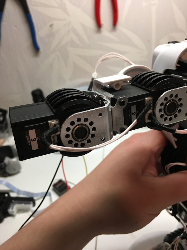
I have these servos in my robot and have now bought the EZ-B V4.
But if it does not get to work, can the Ez b control these servos?
The servos are all connected and the controller only has 1 cable
greetings

Yah - they would be separated for mechanical reasons. The left side is probably one wire and the right side is another wire. But they all group together at the same place to the same connections on the PCB.
I looked around and can't seem to find any info on which wire is + or GND or signal. I'm guessing you can figure it out by looking at the board OR probing the connector with a volt meter
I discovered the voltages with a volt meter: 7,5 v power is center oin , one side is GND, other side is 5 V (control wire, high logic level ). I connected one of the jst plugs and tested the ezb plugin . It was able , by the real time control in the frame screen, via UART and V3,V4,V5, the 3 servos of one arm. The other plugs are probably for the other arm and the two legs. The movement is slow and weak. Those servos, when operated from their controller, are quite fast and strong. I made an action with 2 different frames alternating , pausing for of 500 ms, but it doesn't work. The servos remain in one of the frames. I haven't found in this thread someone who has done such tests. I'd like to hear from someone who did . I hope that DJ could have one servo and some time to do a test , to understand what happens.
Hi all, here is my research and what I found :
Baud rate:115200 Data bit:8 Stop:1 Check:0 Flow control:NONE TTL multi-layer connection,shared-bus ID:1-240 Feedback:position:deviation adjustment,version information
Serial parameter:115200,8,n,1,1
Protocol analysis
EMBEDDED LED // FA AF 01 04 00 00 00 00 05 ED switch on led light // no LED on mine // FA AF 01 04 01 00 00 00 06 ED switch off led light// no LED on mine RESPONSE AA + id // not tried yet as I cannot see with my proto board
GET VERSION FC CF 01 00 00 00 00 ED // not tried yet RESPONSE FC CF ED this can be used to check if servo exist in a loop "for id"
MOVE SERVO // FA AF 01 ED whre T1=0 and T2= = TIME to execute in ms / 20 0 to 255(FF) ie 5.12 second to execute RESPONSE AA + id // not tried yet as I cannot see with my proto board
GET POSITION // FA AF 02 00 00 00 00 ED // not tried yet REPONSE FA AF 00 00 ED // not tried yet as I cannot see with my proto board
SET OFSET ANGLE // FA AF D2 00 00 ED where A1 adjValue/256 and A2 adjValue%256 // not tried yet RESPONSE FA AF {AA + id} 00 00 00 00 ED
GET OFSET ANGLE // FA AF D4 00 00 00 00 ED // not tried yet RESPONSE FA AF {AA + id} D4 00 00 ED where A1 adjValue/256 and A2 adjValue%256
All works now, just think to cross wire in the daisy chain, else GND become DATA on next servo and block all transmission....
Only one way to find out Give it a try!
hi
there are no updates for win7