
Andy627
Germany
Asked
— Edited
Hello, I have a question .
I have these servos in my robot and have now bought the EZ-B V4.
But if it does not get to work, can the Ez b control these servos?
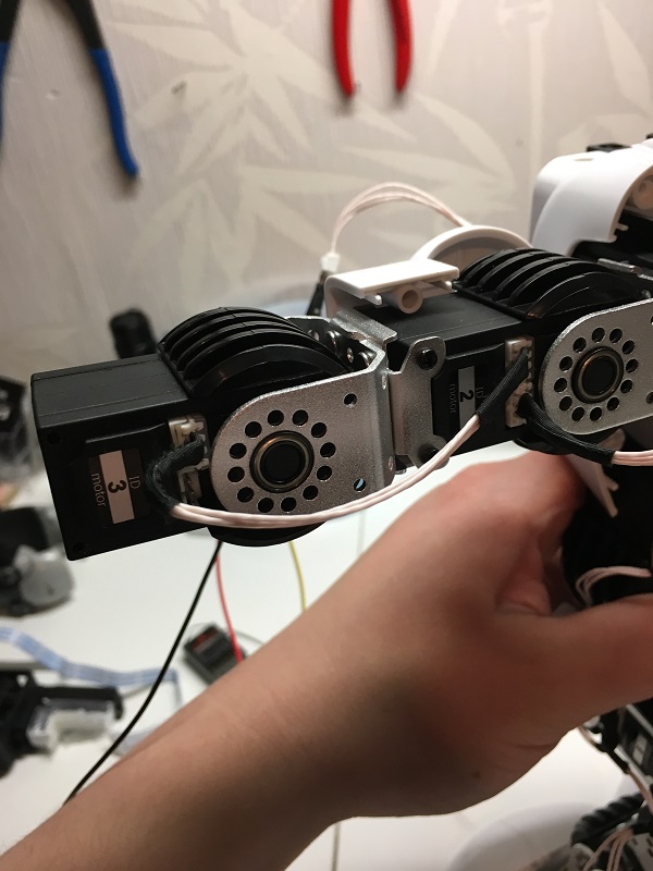
The servos are all connected and the controller only has 1 cable
greetings

Yes, I got the warning you say in the win 7 PC, but everything seems to work. I intend to test alpha 1S servos with ezb v4. The servo plugin seems to work. Now I have only this old PC available for this test. I need information about the hardware connection of those 16 servos to ezb. I asked for this in another post. Can you help ?
Wish I could help - but i do not have a servo or that robot to test with. In this conversation thread, there is someone way way up there who had a link to someone who reverse engineered the protocol. Maybe they showed how to connect the wires? I also believe Nink got them working, as he stated above. I would recommend browsing this conversation thread. There's 92 comments on that developed this thread - with great help i hope
I posted in this thread a photo of the robot controller, showing 4 JST plugs connecting to 4 serial buses to the servos. The servos work connected to a common line, addressed by their specific address , the way it happens in a serial I2C bus. Somebody has certainly tested this connection, but I don't know how to communicate with him. I hope he will reply to this post.
It isn't i2c. It's UART, as stated everywhere in this thread AND the plugin description. All you need to do is identify the Data, GND and Power wires of the servo connector. Follow the instructions on the ubtech plugin page here: https://synthiam.com/Software/Manual/UBTECH-Alpha-Servos-UBT-12HC-16022
If you read this conversation thread as i stated, you will find that there is a link that discusses the ID's and how it works. You will need to put a little leg work in to get it rock'n. Each servo has an ID. The lowest ID is 1. I'm sure the UB Tech software shows what ID is for what servo. If not, you'll have to experiment and try.
Connect them as described by the plugin. To the UART that you choose and power and gnd. I don't have a servo, but it would be pretty easy to look and see what wires are for what. Or, use google to research and find it. That's all i can do to help
I know it's not I2C. I meant that those servos work on a common bus (like I2C does), instead of individual connections like usual PWM servos.
I think all the 16 servos should work on a single control line. I'll study the plugin information , looking for details., i.e.:
I hope that experienced members could explain . In lack of information , I'll look at the control pins with an oscilloscope a let everybody know.
Yes one control line can control all 16 of the servos all at once. The timing is set so the servos and the EZ Robot board always send and receive at the right times. You can use the IO Tiny with a camera to make this robot do much more than it could before.
Thanks, mcsdaver. Alpha robot has 4 jst plugs with 4 separate 3-wire cables to the servos (as you can see in a previous post of mine). I think they are separated only for mechanical convenience of wiring, but probably they are all connected together in the pcb. I see no logic reason to control several groups of servos independently by the controller. I assume that the ezb v4 (uart or digital pin) can drive the common line of all the 16 ubtech servos. Do you know which jst pins are +,-, rx/tx ?
I don't have the same servos that you have, so I am not sure how to connect them to the V4 or IO Tiny.