
Andy627
Germany
Asked
— Edited
Hello, I have a question .
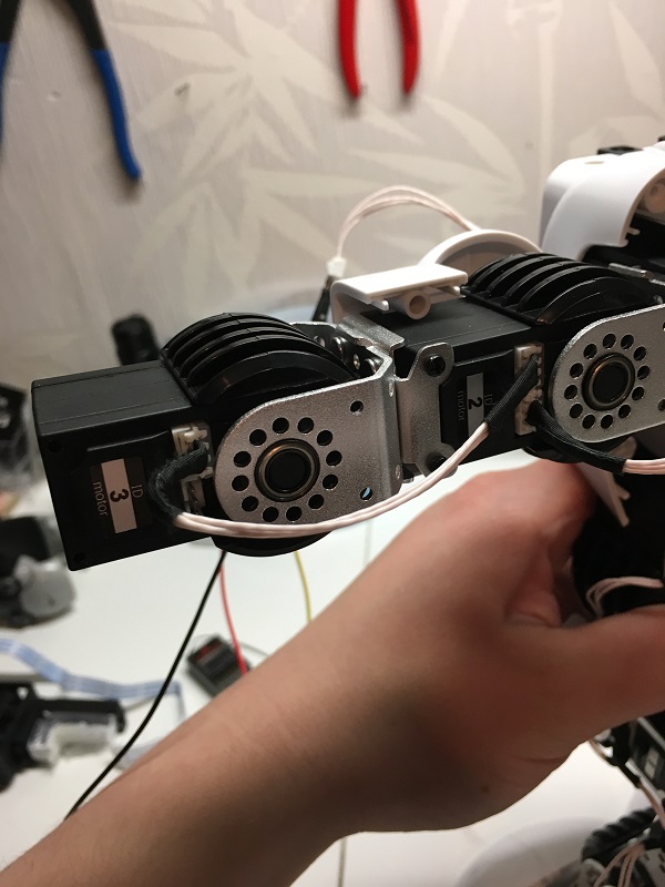
I have these servos in my robot and have now bought the EZ-B V4.
But if it does not get to work, can the Ez b control these servos?
The servos are all connected and the controller only has 1 cable
greetings
Servo brand and model ?
or
Product/Kit details ?
It is the Ubtech Alpha s1
Data of the servo:
UBTECH Alpha 1S Robot Parts Digital servo UBT-12HC
description:
Model UBT-12HC
Communications: Serial communication
Speed: 6.5V: 0.238sec / 60 ° 8.5V: 0.198sec / 60 °
Torque: 6.5V: 8kg.cm 8.5V: 12kg.cm
Gear: Copper alloy gear
Bearing: Ball Bearings
Angle range: 0-180 °, Adjustable
Dimensions (mm): 44 * 22.5 * 29
Weight (g): 42
Amount of operating voltage (V): 7.4V
Stable Current: 2.5A
Operating temperature range: 0-55 ?
Protection: Over Voltage, Over Current
Dead bandwidth (no reaction zone): 0
Feedback: Position / angle feedback
this is the only link i can google.
ubtech
Alan
Serial protocol for the servos.
Alan
Sorry for the questions I'm newbie
Very unlikely UB is going to provide this.
Alan
Then I'll have to resell the Ubtech again
what is it what you try to do ?
he wanted to use the UB servo's on ezbv4 ?
or does he wanted to make a robot ?
Hi Andy , that information is confidential and we can´t share it.
I've been able to find the following,
from
https://alexsonea.com/2017/10/15/jimu-hacking-the-communication-protocol/
For the time being here is a summary of the finds:
the communication is at 115,200bps
packages are send separately by servo; it doesn’t seem to be a bulk send instruction
the package has the following structure:
byte 1 and 2 = preamble = 0xFA 0xAF
byte 3 = servo ID
byte 4 = Command; for go to command we have = 0x01; we will try to find some other commands shortly
byte 5 8 = Command parameters; for command = 0x01 (go to) they are:
byte 5 = position = 120 + desired position in degrees
byte 6 = duration = duration in ms / 20
byte 7 = 0x00 (? we don’t know what this is yet)
byte 8 = 0x01 (? we don’t know what this is yet)
byte 9 = checksum = sum(byte 3 through 8) mod 256
byte 10 = closure = 0xED (from END?)
the servo returns one byte that seems to contain something specific to the ID of the servo (for ID 1 it answers with 0xAB, for 5 it answers with 0xAF; the content could be a status information where each bit has a meaning, similar to the status packet in the Dynamixel protocol
https://www.thanksbuyer.com/ubtech-alpha1s-digital-servo-built-in-avr-develop-board-6v-9v-ubt12hb-55166Protocol analysis method:(need robot)
FA AF 01 04 00 00 00 00 05 ED switch on led light
FA AF 01 04 01 00 00 00 06 ED switch off led light
Write servo:FA AF id 01 angle ? ? ? SUM ED
Servo response:FA AF id AA ? ?real angle sum ED
Read data:FA AF id 02 00 00 00 00 SUM ED
Present experiment order (CD order is modification servo ID.)
Order can do experiments in 01..FF sequence.
Frame header:FA AF;frame ender:ED,SUM=ID+order+parameter,get the lowest 1 byte
Frame header (2 byte) ID(1 byte) order(1 byte) parameter (4 byte) SUM(1 byte)frame ender(1 byte)
Communicaton protocol format (length:10 byte)
Initialization,electricity is on.And then separate it and control single servo with computer TTL.
Connect computer TTL serial to the servo port.The computer (sscom32 serial software) can record it to the file when playing robot.
Protocol analysis method:(need robot)
Modify ID:FA AF ID CD 0 newid 0 0 SUM ED
being able to control this LED eye with ezb would also be very cool ( https://alexsonea.com/2017/11/19/jimu-led-light-breakdown/ ) unfortunately I don't have the skills to create a plugin, but would be more than happy donate some $ to someone who can
They should. From what I could find, they are 7.4v, so OK to use a 2s LiPo battery (recommended for EZ-B) to drive them directly from an EZ-B without worrying about alternate power or voltage regulators.
Alan
robo soul
then your batt is empty.if you want to build a complete robot you need a batt,
aleast 2500 mah
servo robot
you will need to adjust a lot.all standard jd have to go.
and make your own.
you have to adjust everything.also calibrate everthing with the levers and horns,
off.the problem with raising arms is solved,found that one.
now hope i get the walking and sit down and so.
Edit the frame that is assigned to the STOP action and move his arms into the position that you wish.
Locate the name of the frame that is assigned to STOP action...
Edit that frame...
i found this .sofar ok but walking will be really diff.
1) Connect the servos to the UART #0 TX
2) Power the servos with appropriate power
Code:
I love the work you're doing and the community's help with your project.
Scott
I should be able to test out the script tonight, sorry for the late reply just got back from holidays.
Nick
Great news the script works, tested on ubtech servo's for alpha 2 and the Jimu robot set
thank you so much for taking the time to create a plugin for these servos I really appreciate it
Nick
So does that mean the position is between 120 and 255?
Can you remove the GetRandom() and change it to some values to find the max and min positions values for me?
all I did is connect the positive and negative of the servo to D0 and the control wire to TX from uart0
i have an alpha2 too and a metal robot.
thanks
Patrick,
The script was just for testing. DJ is going to write a plugin based on the results. You don't need to do anything with the script and should not use it.
Alan
did you open your alpha 2.?
just had an opportunity to try the plugin but can't get it to work
added the plugin to a new project with the following settings
Hardware uart0 two virtual servos checked V1 and V2
plugin shows Connected Events UART 0 @ 115200bps
added a Movement Panel and added the 2 virtual servos
tried moving the servos but nothing happens?
the script still works fine
running windows 10 with latest updates
2) What Movement Panel did you add?
3) the plugin removed the 120+position as we discussed. To clarify, in your testing you also removed the 120+? So you tested with 0 and 252? Not adding 120 to anything?
4) Also, can you try it with only one Servo?
2) I tried both
3)yes I removed the 120 from your script and inputed the values from 0 - 252 directly into $data[4]
4) have tried both servos separately no difference
also noticed that once I remove the Ubtech plugin from a project and try to add it again it crashes the plugin on startup and the only way to get it to load again is by restarting windows. Unfortunately I was unable to get a screen shot of it last night, will post later.
I will load ARC on a another computer and try that just in case
Nomad, have you had a chance to try the plugin ?
I said that you should let others help with the test script and wait for the plugin. We are now talking about the plugin. You should try it.
Alan
the plugin is for UB tech servo's only.?
Code:
And tell me if the servo moves using the plugin and this script - thanks!
Plugin link: https://synthiam.com/redirect/legacy?table=plugin&id=240
Sorry no, been away from home on business since last Thursday, back Friday will be able to test then.
I’d be more than happy to send you a Jimu robot kit with servo’s from amazon if it would make things easier ? Just email me a shipping address
Either way I’ll do the tests you’ve asked for by Friday
Nick
The plugin works great, had problems initially with it crashing on startup but this seems to be resolved after a windows reload
tested so far with 3 different types of ubtech servos chained together, working really well.
I know I'm pushing my luck but a feature request would be to add an option to read a set of linked servos and get it to automatically generate a frame in the auto-position plugin, my reason for requesting this is to make it easier for younger kids to be able to use it to make robot skits.
Thanks again, now I just to give the Alpha 2 an EZB brain transplant
Nick
It needs an EZ Robot upgrade!
They make a set to build a humanoid robot, but it can't hear, see or talk.
If I want it to walk forward then I need to make my own walk cycle for it.
It can't move its head and no lights for eyes.
I just really wanted the 16 servos to use for another EZ Robot!
If they sold these sets with an EZ Robot brain and a camera they would have something super cool.
It would still need a few more servos so it could look around and hands to pick things up.
Glad I have a JD robot, he does everything right out of the box.
I am thinking how would I use the IOTiny with this and I only see this line on wiring:
"all I did is connect the positive and negative of the servo to D0 and the control wire to TX from uart0 " (guess this is with the EZ-B V4)
Do we have specific info on how to do the following with the IoTiny:
"This plugin requires the RX signal wire of the servo be connected to TX of the selected UART or digital port (if Software UART is selected)"
I dont mind buying some EZ-B but I rather stick with a way to use IoTiny if possible.
[color=#442e5f][size=3][font=OpenSans, -apple-system, BlinkMacSystemFont, Segoe UI, Roboto, Helvetica Neue, Arial, sans-serif, Apple Color Emoji, Segoe UI Emoji, Segoe UI Symbol, Noto Color Emoji]do you have any video about this project with the ubt robot?
[/font][/size][/color]
[/font][/size][/color]
I need to know more about interfacing its servos. I saw there's a plug-in and some hardware information.
I need to know, (I hope somebody in the forum has experienced these matters) :
Hardware : I'm attaching a photo, where 4 3-pin JST plugs can be seen. I think each of them drives , by 4 independent serial buses, some of the servos .
Which pins are +,-, rx/tx pin ? how to connect these 4 buses to ezb ? I saw in the forum a simple scheme, but more detail is needed.
Software: the plug-in I found in this forum is designed for such 4-bus hardware , so to control , by ezb, each servo separately ?
attachment
What's going on ?
What's going on?
It looks like the plugin uses a more recent or non existent class/object in an older ARC version.
Keep your ARC updated, is a good recipe to avoid trivial issues.
The latest ARC beta will technically run on Windows 7 but it’ll give a warning because it’s not recommended. Windows 7 was discontinued by Microsoft and no longer supported. This means new features of ARC are absolutely impossible to be supported in Windows 7 because Microsoft doesn’t support it.
*note: do not duplicate post.
I intend to test alpha 1S servos with ezb v4. The servo plugin seems to work. Now I have only this old PC available for this test.
I need information about the hardware connection of those 16 servos to ezb. I asked for this in another post. Can you help ?
Somebody has certainly tested this connection, but I don't know how to communicate with him. I hope he will reply to this post.
If you read this conversation thread as i stated, you will find that there is a link that discusses the ID's and how it works. You will need to put a little leg work in to get it rock'n. Each servo has an ID. The lowest ID is 1. I'm sure the UB Tech software shows what ID is for what servo. If not, you'll have to experiment and try.
Connect them as described by the plugin. To the UART that you choose and power and gnd. I don't have a servo, but it would be pretty easy to look and see what wires are for what. Or, use google to research and find it. That's all i can do to help
I think all the 16 servos should work on a single control line. I'll study the plugin information , looking for details., i.e.:
1) Direct connection of one digital or UART ezb port to a single servo control line, with 16 servos on it ?
2)Control wire is bi-directional. What happens if ezb sends bytes to servos while servos themselves are sending bytes on the control line ?)
I hope that experienced members could explain . In lack of information , I'll look at the control pins with an oscilloscope a let everybody know.
The timing is set so the servos and the EZ Robot board always send and receive at the right times.
You can use the IO Tiny with a camera to make this robot do much more than it could before.
Alpha robot has 4 jst plugs with 4 separate 3-wire cables to the servos (as you can see in a previous post of mine). I think they are separated only for mechanical convenience of wiring, but probably they are all connected together in the pcb. I see no logic reason to control several groups of servos independently by the controller.
I assume that the ezb v4 (uart or digital pin) can drive the common line of all the 16 ubtech servos.
Do you know which jst pins are +,-, rx/tx ?
I looked around and can't seem to find any info on which wire is + or GND or signal. I'm guessing you can figure it out by looking at the board OR probing the connector with a volt meter
I connected one of the jst plugs and tested the ezb plugin . It was able , by the real time control in the frame screen, via UART and V3,V4,V5, the 3 servos of one arm. The other plugs are probably for the other arm and the two legs.
The movement is slow and weak. Those servos, when operated from their controller, are quite fast and strong.
I made an action with 2 different frames alternating , pausing for of 500 ms, but it doesn't work. The servos remain in one of the frames.
I haven't found in this thread someone who has done such tests. I'd like to hear from someone who did .
I hope that DJ could have one servo and some time to do a test , to understand what happens.
here is my research and what I found :
Baud rate:115200
Data bit:8
Stop:1
Check:0
Flow control:NONE TTL multi-layer connection,shared-bus
ID:1-240
Feedback:position:deviation adjustment,version information
Serial parameter:115200,8,n,1,1
Protocol analysis
EMBEDDED LED
// FA AF 01 04 00 00 00 00 05 ED switch on led light // no LED on mine
// FA AF 01 04 01 00 00 00 06 ED switch off led light// no LED on mine
RESPONSE AA + id // not tried yet as I cannot see with my proto board
GET VERSION
FC CF {id} 01 00 00 00 00 {sum} ED // not tried yet
RESPONSE FC CF {id} {V-1} {V-2} {V-3} {V-4} {sum} ED
this can be used to check if servo exist in a loop "for id"
MOVE servo
// FA AF {id} 01 {angle} {time} {T1} {T2} {sum} ED whre T1=0 and T2= {time}= TIME to execute in ms / 20 0 to 255(FF) ie 5.12 second to execute
RESPONSE AA + id // not tried yet as I cannot see with my proto board
GET POSITION
// FA AF {id} 02 00 00 00 00 {sum} ED // not tried yet
REPONSE FA AF {id} 00 {angle} 00 {real} {sum} ED // not tried yet as I cannot see with my proto board
SET OFSET ANGLE
// FA AF {id} D2 00 00 {A1} {A2} {sum} ED where A1 adjValue/256 and A2 adjValue%256 // not tried yet
RESPONSE FA AF {AA + id} 00 00 00 00 {sum} ED
GET OFSET ANGLE
// FA AF {id} D4 00 00 00 00 {sum} ED // not tried yet
RESPONSE FA AF {AA + id} D4 00 00 {A1} {A2} {sum} ED where A1 adjValue/256 and A2 adjValue%256
All works now, just think to cross wire in the daisy chain, else GND become DATA on next servo and block all transmission....
Any hint? Thanks!
Any hint how to try it?
Those motors I commented about are from the UBTECH ALPHA MINI robot, which came later than the Alpha 1 and 2, hopefully they use the same code!
there are no updates for win7