
RR333
USA
Asked
— Edited
Connect L298n Motor Driver Hbridge To Ez-B Robot Controller V4 Update
Is there an updated version of using this H-Bridge with the EZB v4? I'm assuming (again) that it is the same... But Power? Not using the Battery pack
Thanx:)

https://synthiam.com/Community/Tutorials/130/1
Alan
L298n Motor Driver Hbridge I HAVE ON ORDER:)
bUT, I found this Hbringe in a static bag, in my box of parts. How would be the best way to hook up to the EZBv4?
https://www.robotshop.com/en/dfrobot-4-8-46v-2a-dual-motor-controller.html?gclid=COqghq2MnM8CFYMmhgod8BUCrg
(SAME AS THIS ONE, but that was for the EZBv3 board) https://synthiam.com/uploads/ez_b_hbridge_v2-634625139534279890.jpg
tHANX:)
With a quick glance, almost exactly the same. This is because the board can supposedly take 6-12v on logic, so that means as long as your not powering the ez-b with something over 12v, you should be good. Motor power can likely come from the ez-bs power source, as long as the motor can handle that power.
It's an L298n based H-Bridge which means connections and operation are the same as the one in the link Alan provided or as the image on the page you linked to
It doesn't have an on board voltage regulator for the logic that I can see though. I'd add a 5v regulator to the logic supply (VD) despite it claiming to be able to accept higher voltages.
It also looks like it doesn't have speed control (EnA & EnB) so the motors will move at full speed whenever E1/M1/E2/M2 are set to move the motors.
It's also labelled a little differently but should be simple enough to work out.
You also need to pay attention to the Supply Switching Jumper. Don't feed your the motor power to the logic circuit accidentally.
Manual is here which should help wire it up and configure the M1/E1/M2/E2 correctly.
Hope that helps
from the manual: Pins E1, E2: PWM control the velocity (0=Stop, 1=FULL Speed) Pins M1, M2: Direction 0 = Forward, 1 = Reverse
from the specs: High level: 2.3V = Vin = Vss Low:-0.3V = Vin = 1.5V The logic part of the input voltage: 6 ~ 12V
switch: keep/ON: if your motors accept 6 to 12V remove/OFF: motors need less than 6V or 12-46V
you don't need a voltage regulator, the circuit has one CX1117-5.0, circuit on the right side (3 legs)
the voltage drop is between 1V to 1.3V (max current), to work you will need 6.5V to 12V.
the circuit in the left is a NAND gate, using 2 x (PWM and Direction) transforms to EN1, EN2, INA1, INA2, INB1, INB2 found in most h-bridges.
***disclaimer: I own a DFRobot Romeo controller board with a h-bdrige, similar logic (PWM + DIR)
Awesome feedback! Thanx so much!:)
Not sure how to connect to the EZB v4 though..?
you will need 4 digitals pins to control two motors:
D0 - E1 D1 - M1 D2 - E2 D3 - M2
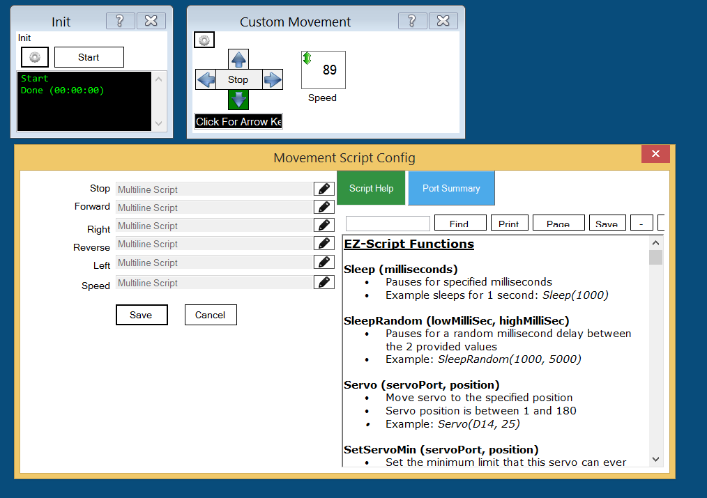
and you will need a Custom Movement Panel. Do you need help with the Custom Movement Panel ?
thanx....I think I have the Movement Panel . That's straight forward...
Hopefully the last stupid question. (I'm used to servos, not H Bridges. on D0 through D3 on the EZB4. I'm not using all 3pins (blk/Red/WHt)for each, so which ones do i USE to M1,,,etc?