Asked
— Edited
5V Relay Not Responding As It Should
So I've just been trying out a 5v relay (with 5v regulator) on port D0 but it's not working as expected. I first tried "Set(D0,on)" and it closed the relay switch. I then tried "Set(D0,off)" and it wouldn't open. I disconnect it from the EZ-B and it opens, plug it back in and it closes again but can't control it from then onwards. I even tried a combined script...
Set(D0,on)
Sleep(2000)
Set(D0,off)
but no change. I'm I missing something here or is there something else I can try?
Thanks.

Just guessing, but maybe put a resistor on the signal pin?
Thanks for replying @Doombot. I just tried it with a 10K Ohm resistor (that's all I have to try it with) in line with the signal wire, but unfortunately no difference.
Soooo, if I understand, you are powering the relay (gnd and vcc) with 5 volts regulated from an external source other than the EZb, is that right?
Then you have the signal line (1nc) going to the D0 signal port on the EZb, is that right?
If the above is true, the solution is simple, you are missing a ground connection between the relay and the EZb.
@Justin He said he had a 5V regulator coming from the ezb...maybe the regulator just doesnt have enough amps to power the coil...Then the solution maybe is to have an external source of power that has enough juice...of course with the grounds all shorted together.
Did you try a different port?
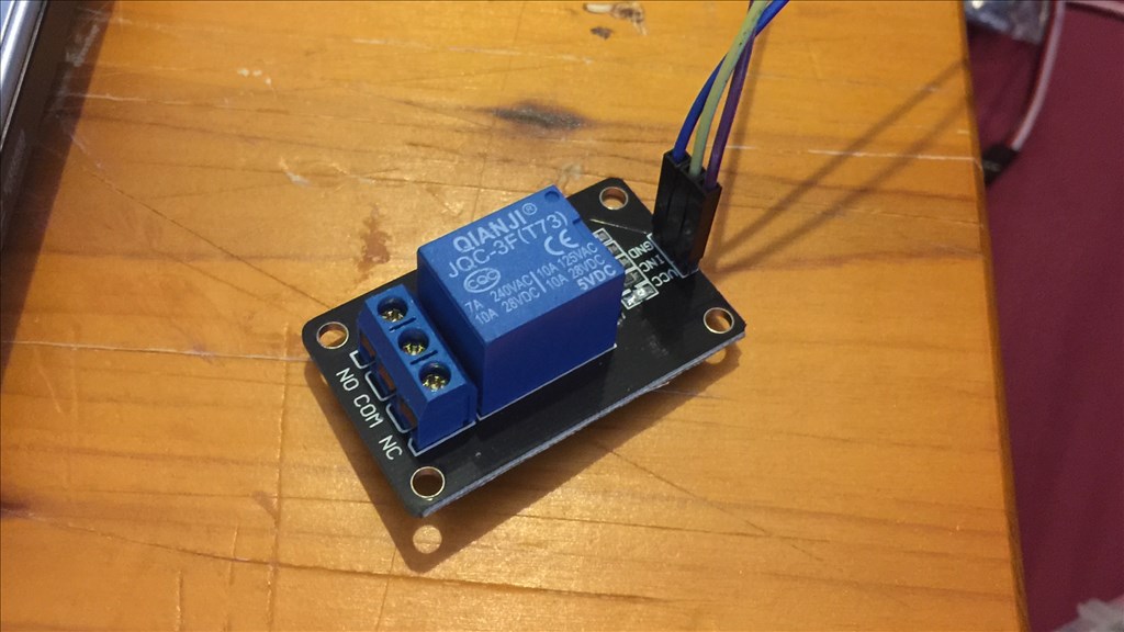
Steve G, is there a driver transistor on the relay PCB?
I use one of these TTL level converter for that relay board..Logic level from EZB is 3.3 v and you need to be 5 v...3.3V-5V 2 Channel Logic Level Converter TTL Bi-Directional Shifter Module.Available on Ebay .
The relay is being powered from the EZ-B through the regulator. I have tried serval ports but to no avail. The regulator I'm using is a 5v, 3 amp output unit. The relay itself is stated as being able to be used with an ARM processor (and a range of others), and needs 15-20mA Driver Current, so I believe it has a driver transistor on the PCB. Here's a close up...