
PRO
RoboHappy
USA
Asked
New Robot , REMI
Thought id share a look at this new kit I received from SuperDroidRobots. Its a 4wheel drive, mobil steel base. All motors are 24VDC. y plan is to move My Hemi bot, with its Actobotics framework over to this base instead.
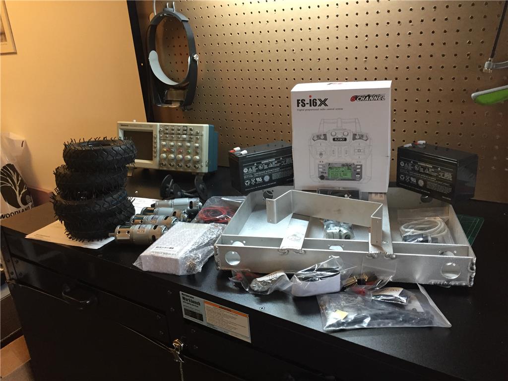
Just getting started, so stay tuned

Hi Folks,
Just a short update on my project...
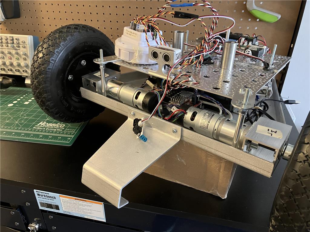
On the front of the drive base, I finally got around to adding a "kick stand" . It came with the from originally but I didnt like how it want bent to be all the way down to the level of the wheels. Its designed to prevent tip-overs. I reshaped it to raise it up some to have a little clearance from anything in its way while driving forward and still acts to prevent tip-overs if it happens.I'm also thinking of adding a couple of bumper switches out front. Also added that Sharp IR sensor. Have yet to figure what it will yet. The USB cable you see hanging off to the side is to interface with the RoboClaw M/C and its pc app. I think I will use that to switch between serial control from the EZB or R/C mode. There are programming buttons on the controller but I cannot access them easy on this configuration.
There will soon be another upper deck added on. So the EZB is planned on being relocated elsewhere.
Well, thats all I have for now .......Progress !
great progress RoboHappy
keep it up :-)
Hello fellow robot fans Just wanted to throw up a few photos of my REMI robots build progress.....
I recently decided to add a couple of bumper switches. Mounted to the forward tilt plate as shown. They are to help stop the robot in the event it mages to get caught up in a corner some how. Also added (not shown) a Sharp IR Sensor on the bottom, behind the switches, also to help if the robot got too close to a stairway edge.
Finally added the second deck. Giving the robot a little extra height and to hide some of the wiring.
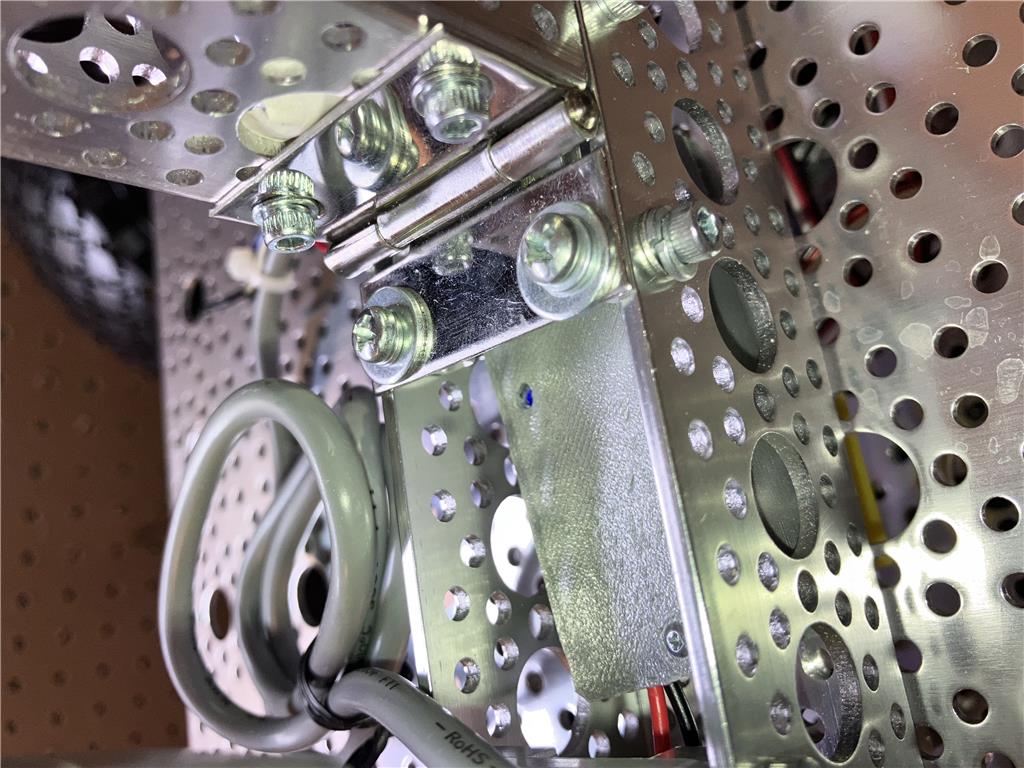
Even decided to hinge on the back side for the upper deck for easy access when needed. I still have yet t o decide where to mount the "main" power switch, and relocate a few other parts.
Another view of the upper deck as I was installing it. The servoCity linear actuator will eventually allow the "spine" of the robot to bend backward some. The idea is to possibly help with "CG" balance if it picks up something too heavy to carry across the room (in theory at least).
Finally found a place to mount an EZB. The EZB will be powered by a buck converter mounted in the rear. And I sorta cleaned up some of the wires from all the sensors.
Hidden away, the EZB's Power supply.That's it for now. Its been quit a process so far, a fun one of course, as my goal is to redo an existing design. The next steps will be the upper spine/torso retrofit.
I like the work you've done so far. Looking more and more like a Mars Rover. LOL
What kind of converter are you going to use to buck down the voltage from 24 volts? You may already thought about this and if so please forgive. But are you planning on running all the power for the rest of the robot like your servos and lights through the EZB from it's power pins? If so you may want to consider running the power for your more power hungry motors and servos around the EZB and directly form the converter(s) to avoid a EZB brown out and reboot. I've had EZB's brown out from just a single servo starting to move.
Keep having fun! I read in another thread that you're going to a different place inn a little while for the summer. I think it was you anyway. If so are you taking this project with you to keep working on it?
Hi Dave,
The main power source is two 12V,7ah SLA batteries wired for 24VDC wired to the drive motors via that funky relay power distribution board (from SuperDroidRobots) on the backside. This board splits up 12 and 24 volts. The drive motors are 24V and only draw about 2amps when running and are controlled via a 2x15a RoboClaw M/C with encoders. The EZB is powered from a 12v Buck convertor, adjusted for 7v and I will run some EZB servos from it. All other servos will be powered thru a Lynxmotion SSC32 that I used before. All the Ultrasonic and IR sensors run off 5V, so they are powered by a little Pololu 12v/5V converter that's good for 5amps (but im only drawing about a lil more than an amp right now.
Hehe, yeah, it looks like a tank right now but soon it will be taller, having a spine that can almost fold up, two 4dof arms with claws, a new head for the camera, and other stuff
Impressive. I'm looking forward to the final product.
Great work, I am also interested to see your final product.
Its been a little while... had life get in the way a little bit So, just a few pics to show off....
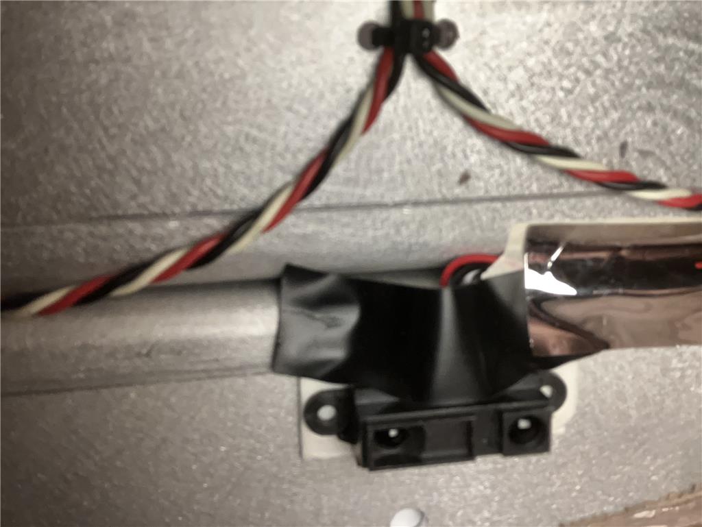
Hard to tell, but this sensor is on the robots bottom (near the from), just in case the robot gets too close to an edge (stairwell), it will then halt and back away.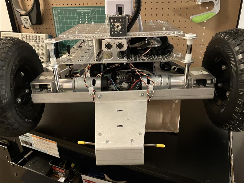
Front view: Added new Main power switch (located above the Ultrasonic sensor). Also two bump switches to the front tilt plate.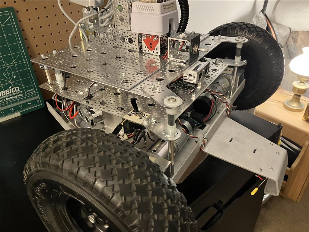
Side view, again showing new main power switch. Lower black switch (I may move) allows to select drive signal between the EZB or an RC receiver to the roboclaw motor controller.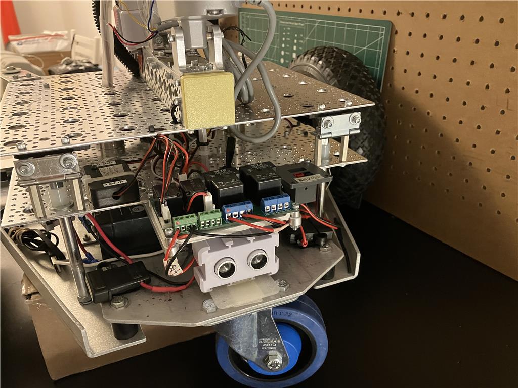
Rear view, I changed out the rear sensor. I was able to get this one to mount better. Also added new fuse holders, mounted with velcro.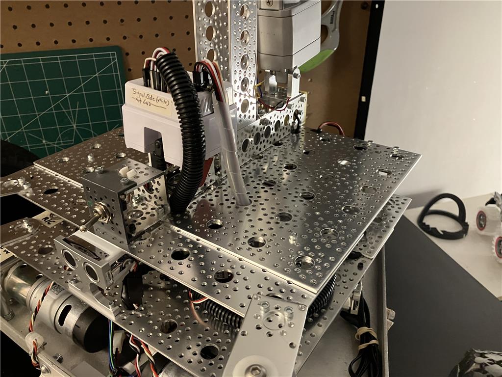
Just another view. I've been thinking about possibly doing something to cover the whole lower base. That will def come way later for sure.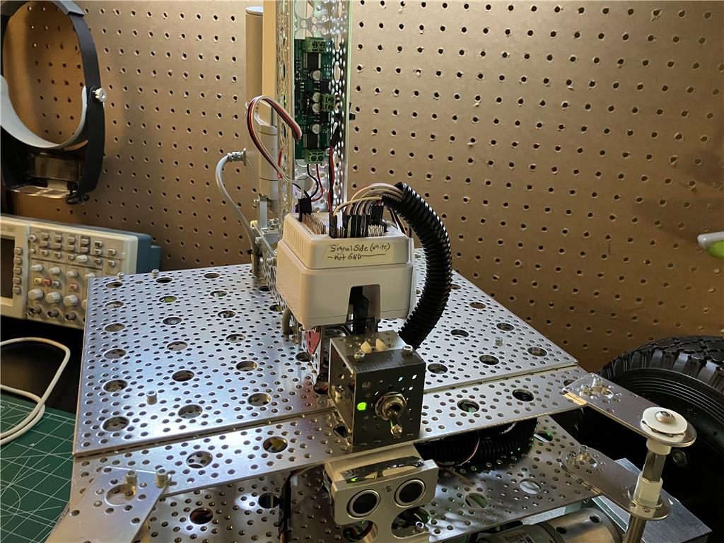
Installed an old servocity 2ch motor control board (seen just above the EZB ). This will control two linear actuators for the "spine" as I like to call it. I will have a video soon to show what I plan to do with this .That's all for now :-)