Asked

New Robot , REMI

Thought id share a look at this new kit I received from SuperDroidRobots. Its a 4wheel drive, mobil steel base. All motors are 24VDC.  y plan is to move My  Hemi bot, with its Actobotics framework over to this base instead.

User-inserted image This kit comes with a RC system and a Sabertooth 2x12RC motor controller which I will be changing out. I also plan on swapping two of the four  motors for two with encoders and use the kangeroo device.

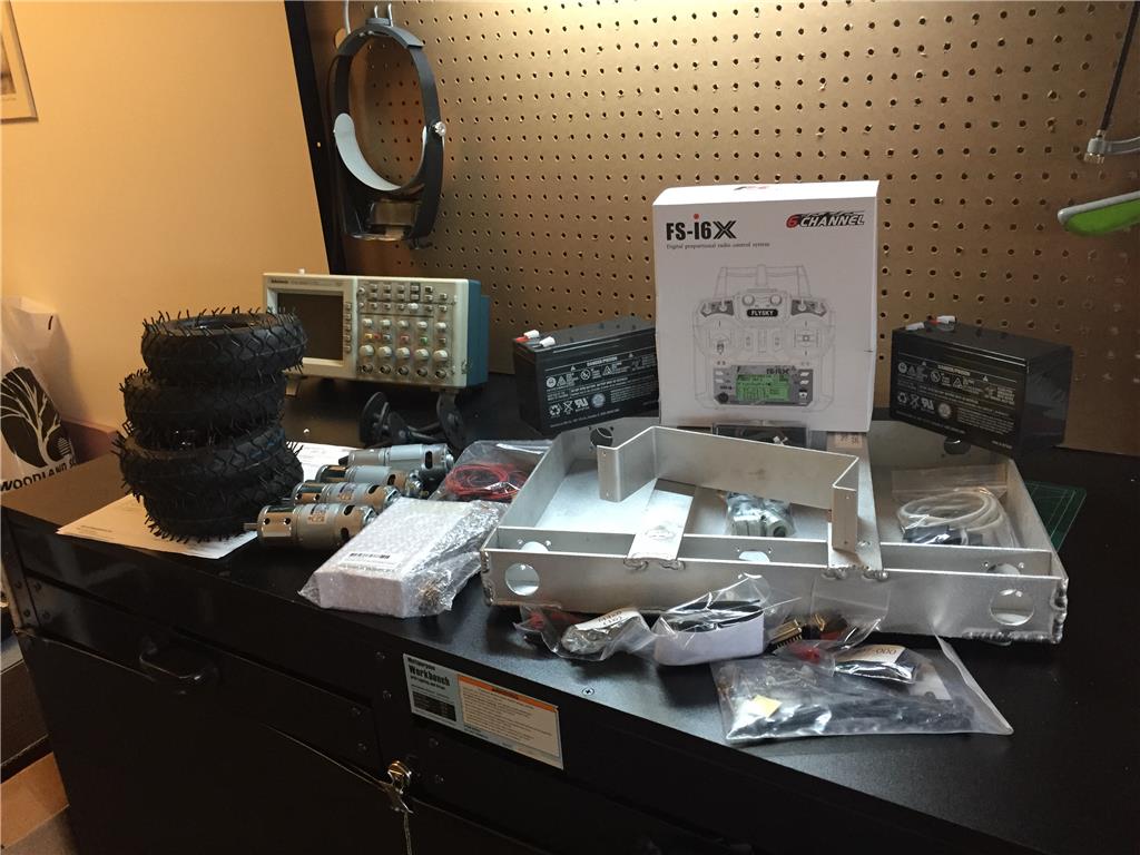
Just getting started, so stay tuned :)


ARC Pro

Upgrade to ARC Pro

ARC Pro is your gateway to a community of like-minded robot enthusiasts and professionals, all united by a passion for advanced robot programming.

PRO
USA
#1   — Edited

Looks Lika a nice project, will be watching your progress

https://www.superdroidrobots.com/    has some stuff

#2  

Thanks :)

While my programming might be a hinder, at least building will be a joy to do.

#3  

Thought Id update my project a little pic. Here are some photos of the SuperDroid Robot base I am working on. The frame is steel, this thing has got soem weight already. User-inserted image 
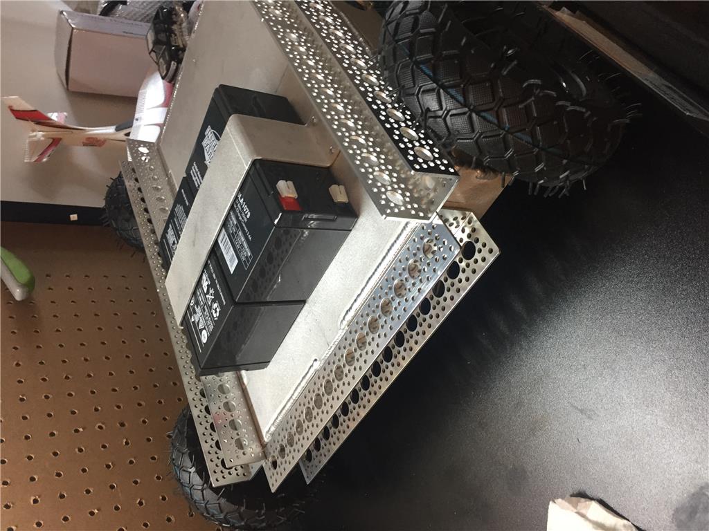
This mobile kit from SD, is a IG42-SB4 series....6" All rubber wheels, four 24VDC motors @ 240rpm (I may reduce), comes with a 2x12 Sabertooth speed controller and the two 12 8ah batteries. Ive started to adapt the Servocity Actobotics hardware onto it as well.

User-inserted image 
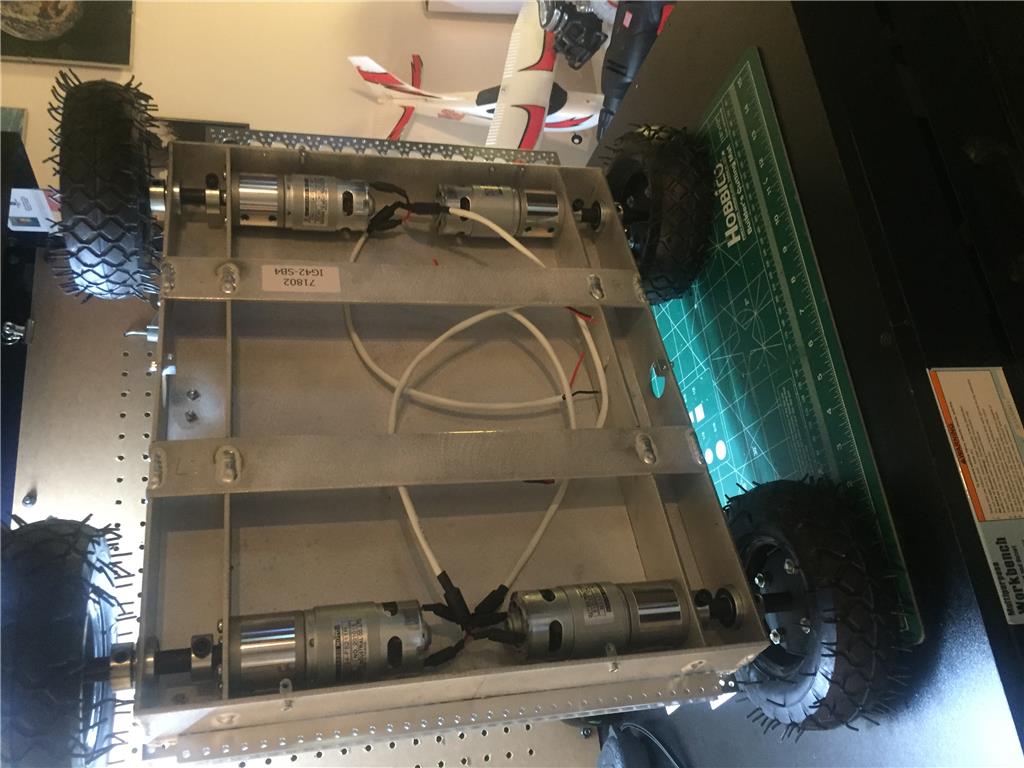
The underside. I Could have ordered a cover plate for it, but Im doing my own. which will made from clear plexiglass.

User-inserted image 
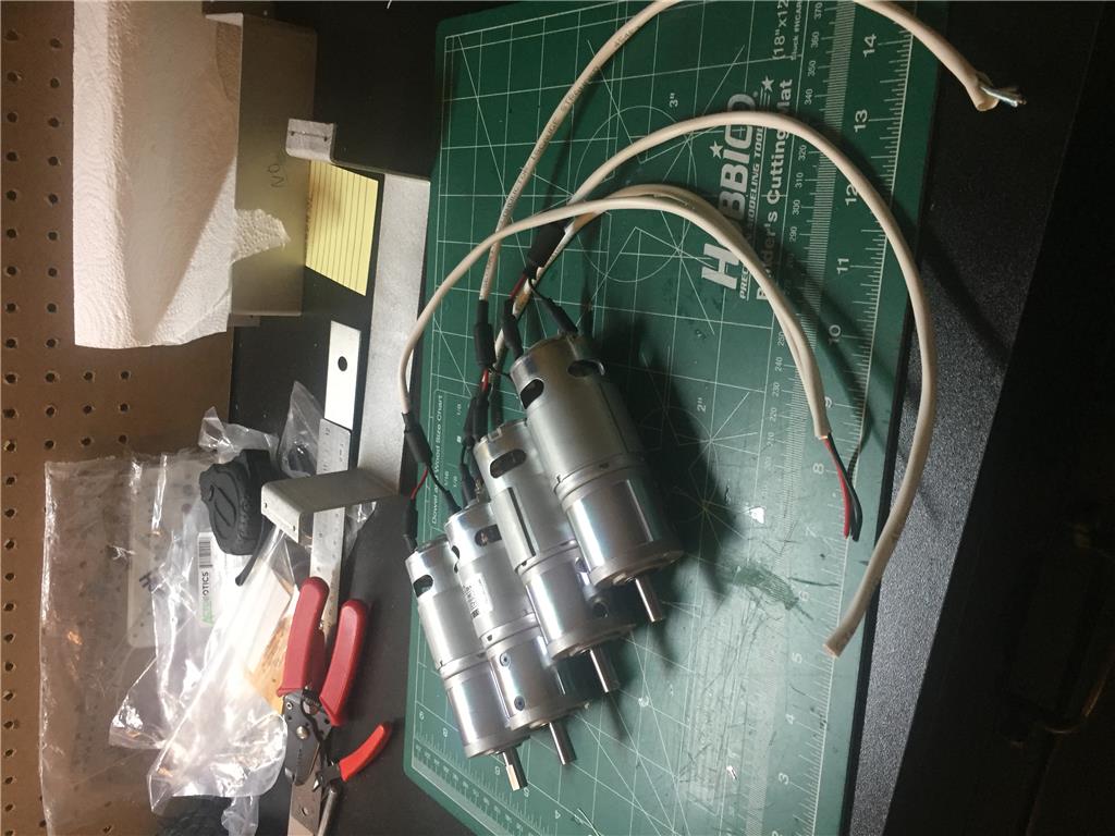
Prepping the motors...

User-inserted image 
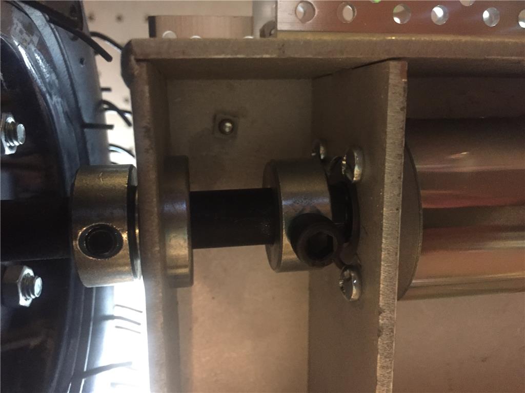
Close up view of the wheel assembly. Will be a pain if I need to change out the motors though.

PRO
USA
#4  

Looks like your project is getting underway.

A big vehicle.

I will be watching your progress, all my best.

be well

#5  

Hello again, So I've decided to make a big change to REMI's robotic base. I'm going from the 4 wheel skid steering  platform that I showed above to now this 2 wheel base, also from SuperDroid Robots. It is a IG42-SB2 tube mount platform. It has 10 inch wheels and a caster at the rear. The motors 78rpm at 24V with quadra-encoders, connected to a Roboclaw 2x15 motor controller. This controller is simular to the sabertooth 2x12, with its built-in encoder setup and can also take simple serial commands from the Sabertooth Movement Panel or custom Movement Panel if desired.  The Roboclaw can also be setup to run via an R/C setup as well, and am currently playing around with different drive speeds for better control.

User-inserted imageUser-inserted image

Eventually, my ultimate goal for this redesign is to transfer the main body from my HEMI robot to this, as I have found out thru trial and error how bad both the the 4wheel base as well as the tank track setup (from Servocity) I first used ran horrible on the carpeting I have all over here. The two wheel design has proved to be much better on my carpet, as well on hard floors.

Stay tuned ....:)

#6  

What size is the base?  Looking down the line to my Inmoov on a motorized base of some sort.

#7  

The overall dimensions for the base are 24 inch in Width, 20 inch in depth, 6 or 10 inch in height, depending on wheels used.  Here is a link to the actuall  drawing if interested for a lil more detail : https://sdr-files.s3.us-east-2.amazonaws.com/product_info/TP-111-042_drawing.pdf

#8  

Thank you!  Wow those are $$$$!  I think I can make for a lot less...  I guess my build will be standing in one place for a while LOL.

PRO
USA
#9  

Hi RoboHappy,

Great going, your project is shaping up

I still play around with the Prowler Robot Kit Chassis from ServoCity  - 4 wheels, I can go forward and back, but can't turn left or right, too heavy, I guess.

EzAng

#10  

Just a quick little video of the new robot platform on the test bench. I was setting up the Sabertooth Movement Panel at the time.... https://youtu.be/KFDzuVtjIoU

More vids to follow ..... :)

#11   — Edited

ROBOHAPPY's wheel base Video. Great work bud!

Here ya go. LOL. Your vid is showcased!

Nice work so far. What fun!

How much more setting up are going to need to do? Looks like the directions are not set up properly to the commands. Also is there a way you can get that Sabertooth to ramp up to full speed?

Any plans on using RC to move this big guy? I know it's very easy to attach an RC receiver to the ST and use a nice RC controller to control your wheel base. That would give you real nice ramping and control.

EDIT: After looking at your pictures a little closer it appears that you do indeed have an RC receiver attached. Wondering what your plans are for the Sabertooth movement panel? Will you be able to use ARC to control this along with the RC controller? I built a tank like wheelbase for my last big robot using a ST controller but only used RC. I wanted to control the wheels with both RC and ARC but couldn't figure how. To tell the truth, I really didn't look deeply into how. There must be a way.

Also that doesn't look like a Sabertooth Motor Controller. Is that  RoboClaw? I'm really interested in this project and will be watching and asking. I hope you don't mind the questions.

#12  

@ EzAng, Thanks. Too bad Servocity has changed things a bit, I might be kinda outta luck I think if I have to replace one of the Actobotic servo gear sets.

@Hi Dave, Thank you for compliments.:D  Good eye on the direction commands. I was trying to control the motors thru the Roboclaw motor controller via the Sabertooth Movement panel. But interestingly enough, I too discovered that the four built in directions were moving the wheels in the wrong directions, this had baffled me. I was looking how the commands were created, looked like done in the java script mode. I had to convert the left and right turn commands to Ezscript and all the directions worked correctly (maybe a bug in code??- don't wanna open a can of worms though). I also played around with the custom movement panel, and so far happy with trying different values to adjust speed.

Before I started using EZB to control, I had an R/C receiver connected to the motor controller. I may plan on doing the same I did with Hemi, having both an AI control or R/C control for the drive systems. What I discovered is, these motors at full speed really move and its a bit jolting when you give the command to 'stop" , the bot almost tips over, so I am planning on much slower speed under the EZB, and the full speed when under R/C control.  I had originally built me a small relay panel to switch back/forth from the R/C to AI, and want to do a better one now.

I also still want to do some ramping speed control. Esp because I will be using the EZB sonars. Haven't found anything on the site that looked to work for me just yet ( anyone got an idea? )

Next step soon is start building upwards. I have plenty of Actobotics metal  to add more support structure. I plan on adding on  long beam (the bots spine I guess) and want to see what tipping over issues I might have while the bot moves around.

#13  

Thanks, very interesting. I'm pretty sure you can set ramping rates in both the Sabertooth and Roboclaw motor controllers. Not sure if it can be done with the dip switches or you need to go into them with the setup software. Once set you won't need to worry about sudden stops and starts.

PRO
USA
#14  
What I discovered is, these motors at full speed really move and its a bit jolting when you give the command to 'stop" , the bot almost tips over,

This happened to me on Mr. Metal, "too tall" is not so good, I figured out.

EzAng

#15  

EzAng, I too found that out when I was building HEMI :(. It would do the same jolting stop with the tracks. That robot is a mere 5 feet tall. I am hoping to make the new one 6 feet if possible.  I did happen to buy a "kickstand"  for the new platform as an option, to prevent the tipping. But I found that this piece of metal will slide along the floor, which is no good for me since I need everything to drive over things like door jams. Im hoping to bend this metal piece for the clearance I need. Will see...

#16   — Edited

Hello there. Just showing off a little addition to the platform. Excuse the mess. As you can see, I've added a platform, just above the batteries. I may add a second platform. This platform will house the  EZB and other electronics and will serve as the main point that I will add more structure. User-inserted image

User-inserted image Now , If could just get these pictures to upload in the right orientation , :)

#17   — Edited

Nice! You gotta have a equipment shelf. Now you have lots of room.

I also have had problems with adding pictures to this site and having them in the right orientation. Sometime it works, sometime not. It may be the size and shape of the uploaded pictures? Maybe reduce the size of your picture and repost? Anyway, I don't think it's us. It's the website not being able to handle what we upload. At the least the person handling the site should post requirements for picture uploads to get them to post properly.

#18  

I may be wrong here about the picture orientation but most websites I have found, usually place the largest side of the picture at the top? When you take pictures to upload, turn your camera sideways (landscape view). This is not always the case but if it is then the proper alignment should take place?

My 2 cents.

PRO
USA
#19  

I use Microsoft Office Picture Manager -  free

fix any picture

EzAng

#20  

If you are using a Mac let me know and I can tell you how to correct them really quick and easy.

#21  

Hi gang, Its been a lil while since I've updated this. Been having a bit of "Designers Block"  as I've had too many ideas on what part of the robot to work on next. Along with life getting in the way of course. Here is a small update on where I am currently at...

User-inserted image A concept of adding the robot spine. I had the bot roaming around via EZB and RC control to see if Id have major  balance issues. So far so good. User-inserted image Im planning on 4 Ultrasonic sensors (from Parallax). Id like to see if I can use these with ARCs NMS feature if possible. User-inserted image Added a second shelf. Am planning on electronics and another battery on these. Also note, the small U-channel on the top. This is for the spine, as shown earlier , in which I am planning on making it bend. User-inserted image Forward sensor. Also plan on adding the RoboClaw motor controller here somewhere.

Stay tuned for more.... :)

PRO
USA
#22   — Edited

Interested to see all the functions of your robot

With my wheels - Alway with a large robot I had balancing issues...

Trying to think of a new robot to create, seem like they all been done on our consumer level

I will stay tuned to see your robot

EzAng

#23  

@Robohappy, are you using GoBida (Metric) or Actobotics (Imperial) parts?

I used to use nothing but the Actobotics line. Mainly because that's all that was available through ServoCity when I started building. Now I'm doing lots of upgrades to my robot. I'm finding that the most available but better built and thought out materials available are the GoBilda line. Lots of the Actobotics stuff at ServoCity is being phased out. I like the Gobilda line a lot but integrating the two lines is a headache. The hole spacing and the part sizes are way different. Even the threaded and unthreaded screw holes are different. #6-32 verses M4. It's doable with some cobbling though. Trips to the hardware store are common. Sometimes, if possible, I just replace the old Actobotic parts with Gobilda parts to make things simpler. Sadly, I have a lot of old Actobotics parts laying around I can't use now. :(

#24  

Hi Dave, Yes. it's all Actobotics. When I started on the HEMI robot build, I went that way, and bought up alot of the Actobotic kits and their geared servos. Even the Agent390 track robot kit was Actobotics. I Still have alot left, so I am making REMI now with what I have left. I was a bit disappointed that Servocity has gone more the Gobilda direction too. I find there pricing a little too much and I let them know how unhappy I was with them phasing out much of the Actobotics, especially if I have to replace one of the geared servos.  Even with the pinchers I will be using, from VEX robotics, I had seen that they went with a rather sloppy plastic version for one of their classroom starter kits so I went and ordered more in case the metal one gets dropped too. I may try a Gobilda set at some point on another build though. I do have a couple of gobiilda servos I got then they sent on sale to try out and I did happen to purchase the gobilda RC controller when on sale too.

PRO
USA
#25  

Hi Robohappy,

Maybe you missed my post, I Interested to see all the functions of your new robot, what will they be?

EzAng

#26  

Hi EzAng,

Hows Mr Metal?

I'm still deciding on what it will do eventually. lol,  I know the original "human assist lifting" idea is sidelined, since that's way more involved than I thought. But, as a kind of helper, butler bot maybe?

The robot will have the two arms, VEX claws, and the folding spine from the HEMI bot I built before and I am wanting to redo the head somehow (any ideas? )  :). It will still have the camera and various sensors (tbd) and I still wanna get back to all that voice command, face req stuff I tried to work on before.

Oh yea, Still doing more driving test to see if i will have any unexpected balance issues too. At least with this wheel setup, its not getting stuck on any carpets :)

I will detail more once I get a little further. Have been slowing down some I've noticed lately.

Till next time..... !!

PRO
USA
#27  

Ok,

Mr. Metal, I took off the wheels for now, nowhere for it to travel, lol - I will soon start practicing arms movements and grippers again.

He still talks and RGB Eyes still work.

These are the claws I use on Mr. Metal -  https://www.amazon.com/Hiwonder-Mechanical-Robot-Claw-Gripper/dp/B089KMK954/ref=sr_1_4?crid=2THWS4PT41IPF&keywords=claws%2Bfor%2Brobot&qid=1662666473&sprefix=claws%2Bfor%2Br%2Caps%2C2305&sr=8-4&th=1

Need something new. Looking at a few gps modules for now

That's my 2 cents :-) EzAng

PRO
USA
#28  

Quote:

I am wanting to redo the head somehow (any ideas? )
Maybe some type of Mr Metal head with the servoCity parts might work for you, you can make it any size with their parts, you know...

#29  

Well hello folks ! How have you all been? Its been awhile since I posted any updates on my REMI robot project here. Sorta had a bit of a "designers block" when it came to how I wanted to mount a few things on the chassis. So I stepped away from it all, meanwhile priority of family issues arose once again.

This is but a small update of where I am now with this, So Id like to show off some progress.... Btw, hats off to some of the more recent ideas and designs I have seen around here, great work and a thank you, it actually helped me get back the spark needed to continue :)

This picture shows the robots new "spine", The actuator, from ServoCity, is to help bend the bot in a way that I hope to use for transporting, like in my van if Im gonna take it places. The second pic is the upper body of my old bot "HEMI" for which I'm planning on moving it all onto the new chassis to become "REMI". Cheesy it sounds yea, but it works hahaha. User-inserted imageUser-inserted image I still plan on making a new head, relocate the EZB, and change the shoulders around a bit. Id like to just flip them around from what is shown here. Also plan on doing some serious rewiring as needed.

User-inserted image This a Power Distribution Module (TE-248-220) from Super Droid Robots. It handles how to route the 24VDC (motors) and 12VDC (everything else) that will be used thru-out. User-inserted image The 24v Battery Charging port, mounted there for now.  You will also notice an RC receiver, I am for now, driving the bot around via RC. As you can see I have also mounted Ultrasonic sensors for when i switch to AI mode. Already have had been working on drive speeds using the RoboClaw 2x15 motor controller. Much more work ahead.... User-inserted image Another view. May be hard to see, but the lower chassis has the 2 - 12VDC SLA batteries in place.  Yeah, the wiring looks a mess in there, some sort of "body" to cover it all is an idea once I get closer to the structures finish. Any ideas??:)  User-inserted image So, the base of the chassis is a 3 wheeled design from Super Droid Robots. Using 2, 24VDC  motors and a large caster in the back. The rest of the metal is still the Actobotics series from ServoCity.

That's all I have to show for now:) hope you enjoy. More is on the way of course. Comments welcome  of course. Was nice to finally spend some time to do this

PRO
Synthiam
#30  

Wow, how tall is that going to be? Very cool robust, looking robot

#31  

Hi DJ, If all goes well, Im thinking between 5 to 6 feet tall. I like the idea of it big , lol. I like this new chassis, seems to handle different terrain well so far.

PRO
USA
#32  

Great going RoboHappy

#33  

Nice work. I love how it's coming along. I'm glad you're building again and am looking forward to seeing more.

#34  

Hello again,

Just a small update on things...

User-inserted image This is a simple 12v to5VDC converter I made using a simple switcher module picked up from Pololu (#5851), wired to a Servocity  servo power distribution module to power up the 4 Ultrasonic sensors.

User-inserted image Another view of the wiring.

Sadly, I now have to wait to do more testing. Somehow I did  a rookie mistake and misaligned the 3pin servo wires onto the EZB unit, and managed to fry to fry it. Even worse, did it again on a second EZB (short circuit protection would have been nice) . Already contacted EZ-Robot to see what it will cost to repair the two units or maybe just replace them. At least I now realized how I managed to damage them though, will be way more careful now.

#35  

Heeeees Baaack.... lol Hey folks ! Remi, the robot is back. Slowly but surely  back. After getting my two EZB units repaired (thank you Ez-robot) and dealing with a small family emergency,  Im hoping to get back to finishing this project.

User-inserted image These are just a couple of current views of the Remi Base unit. User-inserted image I am now back to testing the ultrasonic sensors and motor controller w/ encoders again before I move forward. I will also use r/c control for the drive as a manual drive option when not using the sensors . Also might ad bumper sensors. Would like to try the NMS feature at some point too. Hopefully soon, I can move onto adding the rest of the body from my old Hemi robot too.

PRO
USA
#36  

Great, things are shaping up, I will be watching your progress, thanks for the update.

#37   — Edited

Good to see you back! Have fun! I'm also back to working on my robot. It's a good feeling.

I'm looking forward to seeing your progress!

#38  

Hi Guys ! So I am back to working on REMI a lil bit. I'm right now trying to get the drive motor , using a robocloaw 2x15A motor and with a Ultrasonic sensor  to work together. I am having a little trouble getting the sensor to read proper value and make the motors slow down.  What happens now is when I tell the robot to move forward, the wheels do turn  but for a short period then stop. This only happens when I have the ping sensor activated once the motors start forward. Mind you, the motors move forward just fine when the sensor is not involved. I had this working before on my Hemi robot, so im confused why its not working now.

Below is a snippet of the script, which has worked before (but now does not). I'm wondering if someone else can see something I don't. its been setup to only run forward sensor with the drive motors, and using D12 set to simple serial to the roborclaw and D16 for the 3wire ultrasonic sensor, and is suppose to make motors slow down as sensor reads lower values (robot getting closer to a wall example) then will stop.

This variable will be used to determine if we exit.

If it is a 0, we continue running

If it is a 1, we exit this script

$exit = 0

begin moving forward

#Forward()

:Start

Get the ping sensor value

$ping1 = GetPing(d16, d16)

If the ping sensor values are less than:

than 20, slow down or stop.

if ($ping1 < 45) goto(slow) endif if ($ping1 < 35) goto(slower) endif if ($ping1 < 20) goto(stop) endif

#read foot switch #if(GetDigital(D11)=1) goto(footsw) #endif

#read Emergency stop switch #if(GetDigital(D10) =1) Goto (stop) #ControlCommand("RGB Animator", AutoPositionAction, "Idle") #ControlCommand("Soundboard v4", Track_2) #endif

If the exit value is 1, exit the script

if ($exit = 1) goto(Exit) endif

Sleep(500)

Goto(Start)

:slow SendSerial(D12,38400,33) SendSerial(D12,38400,151) #sayEzb("slowing") #ControlCommand("RGB Animator", AutoPositionAction, "Slow") Return()

:slower SendSerial(D12,38400,49) SendSerial(D12,38400,167) #sayezb("much slower") #ControlCommand("RGB Animator", AutoPositionAction, "Slower") Return()

:stop Stop() SendSerial(D12,38400,64) #SendSerial(D12,9600,192) sleep(200) #SendSerial(D12,9600,0) SayEZB("Stopped") #ControlCommand("RGB Animator", AutoPositionAction, "Stop") stop() #Return()

:footsw SayEZB("Stopped") SendSerial(D12,38400,0) Stop() #endif #Return()

:Exit #Stop() #SayEZB("Received Command Stop") Halt()

=========================================================== This is were I am at atm , I wanna get this working proper again before I move onto anything else. If someone seems something odd, please advise, I love the input always. Thank you.

Progress!:) hehe

#39   — Edited

Does your robot say stop when this happens? If you have the variable watcher installed what is the value of $ping1 when it stops?

I'm guessing the reason that your robot keeps moving with the sensor unplugged is because the sensor is not sending any information and the script isn't receiving anything because of that. Therefore it thinks that everything is still all clear in front of it. I've never worked with these sensors but perhaps it is not positioned properly on the robot? Maybe it's seeing the robot itself or something mounted on it?

PRO
USA
#40   — Edited

I tried your code with my IoTiny

it said stopped

:footsw SayEZB("Stopped") SendSerial(D12,38400,0) Stop() #endif #Return()

:Exit

orig

:footsw SayEZB("Stopped") SendSerial(D12,38400,0) Stop() #endif #Return()

:Exit #Stop() SayEZB("Received Command Stop") Halt()

****** SayEZB("Received Command Stop") Halt()

took ***** # off above went to the end

#41  

Thanks for the insight guys:) After playing around some more tonight, I actually made some headway.  After I five the command for robot to move forward, the pin sensor begins looking at the distance. As per the varied ping1 values  I picked the motors do begin to slow down as the obkect (a wall) gets closer,then robot finally stops and says "stopped".  I def have more tweeking to do...

This variable will be used to determine if we exit.

If it is a 0, we continue running

If it is a 1, we exit this script

$exit = 0

begin moving forward

#Forward()

:Start

Get the ping sensor value

$ping1 = GetPing(d16, d16)

If the ping sensor values are less than:

than 20, slow down or stop.

if ($ping1 < 80) goto(slow) endif if ($ping1 < 40) goto(slower) endif if ($ping1 < 20) goto(stop) endif

#read foot switch #if(GetDigital(D11)=1)

goto(footsw)

#endif

#read Emergency stop switch #if(GetDigital(D10) =1) #Goto (stop) #ControlCommand("RGB Animator", AutoPositionAction, "Idle") #ControlCommand("Soundboard v4", Track_2) #endif

#if the exit value is 1, exit the script if ($exit = 1) goto(Exit) endif

Sleep(500)

Goto(Start)

:slow SendSerial(D12,38400,33) SendSerial(D12,38400,151) #sayEzb("slowing") #ControlCommand("RGB Animator", AutoPositionAction, "Slow") Return()

:slower SendSerial(D12,38400,49) SendSerial(D12,38400,167) #sayezb("much slower") #ControlCommand("RGB Animator", AutoPositionAction, "Slower") Return()

:stop Stop() SendSerial(D12,38400,64) SendSerial(D12,9600,192) sleep(200) #SendSerial(D12,9600,0) SayEZB("Stopped") #ControlCommand("RGB Animator", AutoPositionAction, "Stop") stop() HALT() Return()

:footsw #SayEZB("Stopped") #SendSerial(D12,38400,0) #Stop() #endif Return()

:Exit #Stop() #SayEZB("Received Command Stop") Halt()

=========================================================== The script again, as you can see, I had to rem out alot of stuff to just get the "$Ping1" values to be sen by the sensor. As far as the $exit=0 or 1 bit is concerned, that was from a script by someone a ways back when, using up to 4 sensors (this is how I started). Im looking to have sensors, front,rear,left,right, and a couple of bump switches for basic collisoin/direction and planning on adding the EZ camera in the mix and still woul like to see if all this will work with the NMS pluggin, but first I need to get the raw sensors to work as I think they should.

And as always, any more thoughts or insights would greatly help.

#42   — Edited

I don't see any Sleep() commands in your script. Do you think it's running too fast and readings and commands are being missed?

When I have a script not working and I have suspicions that it's a timing issue, I slow the script way down and try to watch and see what the last command was that actually was excited.

A number of years ago I used to be able to watch the script run command by command in the script console. Now the only way I can see that happen is to assign a Print() command to something in the script.

@DJ, was the ability to see the script run in the script console removed from ARC or am I doing something wrong? If it was removed why? I'm guessing, maybe performance? If so, to bad, that was such a useful tool.

#43  

Hi Dave, that is interesting. I will look into further. But amazingly enough I was able to get what I wanted basically working last night, was able to get the motors to slow down as Id get closer, then to stop. But yeah I am sure more tweeking could be had.

One thing I redid last night also, after re-reading the users guide yet again on the roboclaw, was I finally got to "Autotune" the motors, each with built in quadra encoders.

Was having a lil more fun with the programming last night too, (robot almost ran over my foot in live testing lol ) with the backup sensor script which oddly seems to stop to quick even no obect is near the sensor distance.

This is my "SensorRr" script with a backup sensor...very basic I think so i'm baffled as to it not working right.

This variable will be used to determine if we exit.

If it is a 0, we continue running

If it is a 1, we exit this script

#$exit = 0

begin moving Backwards

#Reverse() or Backup

:Start

Get the ping sensor value

$ping4 = GetPing(d19, d19)

if ($ping4 <= 20) goto(stop) endif

:stop Stop() SendSerial(D12,38400,64) SendSerial(D12,38400,192) sleep(200) #SendSerial(D12,9600,0) SayEZB("Stopped") #ControlCommand("RGB Animator", AutoPositionAction, "Stop") stop() HALT() #Return()

Ive # out the parts im not using as shown. Script is suppose to stop when sensor reads value at 20 but stops quicker instead. Sensor reads values just fine on its own, no script. odd?

I hope to shortly post a little video of my robots forward test. But def an odd one for the reverse action.

:)

#44  

Here is a little video made showing my progress of the forward drive and the sensor, slowing the motor speed as I get closer to the robot.

PRO
USA
#45  

video?  upload it again please

#46  

Heres a slightly longer video from same test...

https://youtu.be/R29max8YFVQ

PRO
USA
#47  

so are you getting the results you expected?

#48  

Oops, looks like I have to fix that first video.

Hi EzAng, I did make some more progress tonight (after tweaking the code  some more). Still have much more to add abd test before I go any further with the build.

#49  

Hi Folks,

Just a short update on my project... User-inserted image On the front of the drive base, I finally got around to adding a "kick stand" . It came with the from originally but I didnt like how it want bent to be all the way down to the level of the wheels. Its designed to prevent tip-overs. I reshaped it to raise it up some to have a little clearance from anything in its way while driving forward and still acts to prevent tip-overs if it happens.

I'm also thinking of adding a couple of bumper switches out front.  Also added that Sharp IR sensor. Have yet to figure what it will yet. The USB cable you see hanging off to the side is to interface  with the RoboClaw M/C and its pc app. I think I will use that to switch between serial control from the EZB or R/C mode. There are programming buttons on the controller but I cannot access them easy on this configuration.

There will soon be another upper deck added on. So the EZB is planned on being relocated elsewhere.

Well, thats all I have for now :).......Progress !

PRO
USA
#50  

great progress RoboHappy

keep it up  :-)

#51  

Hello fellow robot fans:)  Just wanted to throw up a few photos of my REMI robots build progress.....

I recently decided to add a couple of bumper switches. Mounted to the forward tilt plate as shown. They are to help stop the robot in the event it mages to get caught up in a corner some how.  Also added (not shown) a Sharp IR Sensor on the  bottom, behind the switches, also to help if the robot got too close to a stairway edge. User-inserted image

Finally added the second deck. Giving the robot a little extra height and to hide some of the wiring. User-inserted image

Even decided to hinge on the back side for the upper deck for easy access when needed. I still have yet t o decide where to mount the "main" power switch, and relocate a few other parts. User-inserted image

Another view of the upper deck as I was installing it. The servoCity linear actuator will eventually allow the "spine" of the robot to bend backward some. The idea is to possibly help with "CG" balance if it picks up something too heavy to carry across the room (in theory at least). User-inserted image

Finally found a place to mount an EZB. The EZB will be powered by a buck converter mounted in the rear. And I sorta cleaned up some of the wires from all the sensors. User-inserted image User-inserted image Hidden away, the EZB's Power supply.

That's it for now.:) Its been quit a process so far, a fun one of course, as my goal is to redo an existing design. The next steps will be the upper spine/torso retrofit.

#52   — Edited

I like the work you've done so far. Looking more and more like a Mars Rover. LOL

What kind of converter are you going to use to buck down the voltage from 24 volts? You may already thought about this and if so please forgive. But are you planning on running all the power for the rest of the robot like your servos and lights through the EZB from it's power pins? If so you may want to consider running the power for your more power hungry motors and servos around the EZB  and directly form the converter(s) to avoid a EZB brown out and reboot.  I've had EZB's brown out from just a single servo starting to move.

Keep having fun! I read in another thread that you're going to a different place inn a little while for the summer. I think it was you anyway. If so are you taking this project with you to keep working on it?

#53  

Hi Dave,

The main power source is two 12V,7ah SLA batteries wired for 24VDC wired to the drive motors via that funky relay power distribution board (from SuperDroidRobots) on the backside. This board splits up 12 and 24 volts. The drive motors are 24V and only draw about 2amps when running and are controlled via a 2x15a RoboClaw M/C with encoders. The EZB is powered from a 12v Buck convertor, adjusted for 7v and I will run some EZB servos from it. All other servos will be powered thru a Lynxmotion SSC32 that I used before. All the Ultrasonic and IR sensors run off 5V, so they are powered by a little Pololu 12v/5V converter that's good for 5amps (but im only drawing about a lil more than an amp right now.

Hehe, yeah, it looks like a tank right now but soon it will be taller, having a spine that can almost fold up, two 4dof arms with claws, a new head for the camera, and other stuff

#54  

Impressive. I'm looking forward to the final product.

PRO
USA
#55  

Great work, I am also interested to see your final product.

#56  

Its been a little while... had life get in the way a little bit:) So, just a few pics to show off....

User-inserted image Hard to tell, but this sensor is on the robots bottom (near the from), just in case the robot gets too close to an edge (stairwell), it will then halt and back away.

User-inserted image Front view: Added new Main power switch (located above the Ultrasonic sensor). Also two bump switches to the front tilt plate.

User-inserted image Side view, again showing new main power switch. Lower black switch (I may move) allows to select drive signal between the EZB or an RC receiver to the roboclaw motor controller.

User-inserted image Rear view, I changed out the rear sensor. I was able to get this one to mount better. Also added new fuse holders, mounted with velcro.

User-inserted image Just another view. I've been thinking about possibly doing something to cover the whole lower base. That will def come way later for sure.

User-inserted image Installed an old servocity 2ch motor control board (seen just above the EZB ). This will control two linear actuators for the "spine" as I like to call it. I will have a video soon to show what I plan to do with this .

That's all for now :-)

#57   — Edited

Hey! Coming along great. I like the option to switch from RC to ARC control. I thought about doing this on a big Lost in Space B9 robot I was rebuilding a couple years ago but couldn't figure out how to best way to do it. I know very little about RC control. I didn't think it could be as simple as a on/off switch.

I also like that you're using Velcro here and there. I discovered it a number of years ago. Until then I thought it was a lazy way to attach something that gives you a weak joint. Once I started using it I realized it was a great way to attach non stress load devices and it makes replacement easy. The right quality Velcro has great gripping power and quality adhesive that stays put.

Have fun!!!

#58  

@Dave, Thank you very much :-) I Like watching your B9 builds.  The rc/arc switch allows me to switch the electrical path of pwm or simple serial to the m/c but turns out I still have to connect the m/c to a pc via usb to use an app to tell it which of signal type to accept. There are setup buttons on the controller but cant get to them now. So sadly I cant just freely switch back and forth. Besides, within arc, since we can use the custom Movement Panel Joystick, I found I can use that for manual control instead of an r/c controller. The previous robot, I had two motor controllers wired in, one for ezb and one for r/c, and wired each motor outputs to a big switch to the drive motors since I had the room to do it. I don't have that kind of room on this model this time.

PRO
USA
#59  

Hey RoBoHappy

How is progress going?

#60  

@EzAng

Hiya! progress....slowly but surely ,lol I work on it when I have the time to lately. The other night I did add an LCD Battery monitor and now starting to work on the upper body. I hope to do a quick video of a couple things I'm doing with it soon.

User-inserted image Added a digital battery monitor.

PRO
USA
#61  

That sounds great, good success. Let me know when a video is coming.

#62   — Edited

Finally, a couple of quick videos... One shows the the robot moving forward via voice command. The other shows how the robots spine can fold up ( realy only bends a little).

https://youtube.com/shorts/_1_UIoQtwFM

https://youtube.com/shorts/JUQ6LxwSiNQ

#63  

User-inserted image

Just another view of the front of the base, with LCD battery monitor, forward sensor, and newly located Main Power switch :)

PRO
USA
#64   — Edited

Looks like things are working, voice commands works well,

reminds me a little of my crane I built with voice commands in 2021

Always thanks for your comments,

https://youtu.be/fUQ8eYO8CEY

#65  

Finally... I decided to add the arms... (excuse the sideway view haha) User-inserted image Front of the robot User-inserted image Rear of the robot

I'm happy I was able to move the arms from my Hemi robot to Remi now. Robot is getting taller, which now has brought on its own set of new problems. First off the stability which I really noticed when the robot drives ahead (might see this is one of the recent videos I posted) it wobbles some. I'm thinking either adding some support struts to the lower spine or add add a sorta of support tray to keep things still as it drives forward. Another thing i'm still wrestling with is the robots turning speed. Left or right turns are way too fast and also cause things to swing about. I'm still trying to find some sample code around here that will help me slow this issue down alot. If anyone can point me in that direction, that be great.  Think some redesigning is in need here. One idea I am also still trying to figure out, is Remi's "head". Needs something fitting for this.

PRO
USA
#66   — Edited

Looks good,

I had a similar problem, with height, base needs to be bigger, wider to bear the weight of the height.

One thought: Did you try the servo speed control? Servo Speed - servo - Robot Skills - Support - Synthiam

https://synthiam.com/Support/Skills/Servo/Servo-Speed?id=16044

#67  

Hmmm, interesting. Not sure it will work  for me though. I have to send "SimpleSerial" commands to a Roboclaw controller (acts just like a sabertooth). I used both the Sabertooth and the Custom Movement Panel and created scripts as needed. Except for the left/right turns, which I had to use old ezscript code to get the bot to do a 90 degree turn then stop (just does it too fast)  The Roboclaw does also accepts pwm commands from an R/C receiver, might be an idea to go that route as I think about this:) more.

#68  

Hellooo ! Since Its been awhile, thanks to life in general, figured Id just pop up a couple photos of the progress, which hasn't been too much since Im still making changes as I go along.. (will this ever be finished?? haha) (sorry for the flipped photos again)

User-inserted image This is the rear view of HEMI, but is in the process of a redesign, for a stronger  spine that wont wobble about when it drives around. User-inserted image The "head", which Im still rethinking on what I want to do. I am planning on using 2 EZB units if possible Details to follow.....

Thats all for now.... Please any comments or ideas, I love to hear em!  Happy building my friends :)

PRO
USA
#70   — Edited

Great going,

does it move yet?

Does the height make it wobble?

Happy 4th

#71  

Happy 4th !

I do have it moving about. Finally  worked on slowing it down alot more, especially  when it makes turns. I'm able to use both verbal command and manual control via the movement stick control. Also still have RC control if needed as well.

Yea, the wobble was not good, def due to the height and the fact that I was a little flimsy on the metal support at the base. Im am now looking to beef that up alot, and may get rid of my "folding spine" option. May order another higher torque actuator from Servocity as another option to try as well:) Im being picky with this design I guess, I'm not satisfied until it I get it right lol.

PRO
USA
#72  

any videos yet?

#73  

heh, videos might be awhile, as I still have to put REMI back to together yet. Id like to buy/build a decent camera stand to help me with making videos (holding the phone while trying to make robot move just isnt working for me lol) Stay tuned....

#75  

Hello fellow builders , Its been awhile. Recently had to deal with the passing of my mom, so... Thought id show a couple of changes to the robots design.

I decided to remove the Servocity Actuators from the spine, because of issues with lining things up, annoyed me too much. But left things in place should I  want to do it over again. User-inserted image

A new head. If you can recognise the top ezbit part. I 3D printed a taller piece out of PLA. Looks cool I think. User-inserted image The bot is intended to have 2 EZBs, once I figure out how to connect them properly to ARC. I have alot more to add on. I hope to post more once I have free time again.

Keep on building my friends ! :)

#76  

Hello folks! It's been a while since I have updated my robots progress, So I figured I'd at least show something.....

https://youtu.be/Kz3PccYCDz8

It's just a quick video of some of REMIs movemements:) enjoy

PRO
USA
#77   — Edited

Your doing great, moves well on commands. Great arm movement

Great to see a robot again.

I might revive Mr.Metal, been playing with LEDs, servos, Car with camera.