
Describe Your Robot Arm For Kinematic Robot Skill
We are in the process of developing a dynamic configuration system for robot arms, which will be compatible with a variety of robot arms and joint numbers. We kindly request your valuable input regarding your robot arm configurations to make this system as versatile and effective as possible.
One of the critical aspects of this project is understanding the layout and specifications of various robot arms. Your insights and contributions will significantly aid in developing this dynamic configuration system. Here's what we're interested in:
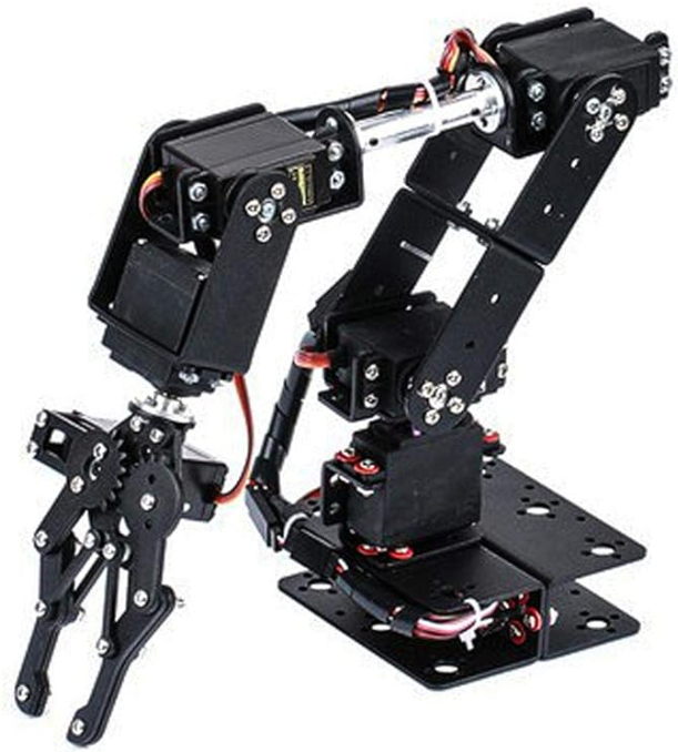
1. Configuration Description: Please describe or provide a picture of your robot arm's layout. Share details such as the number of joints and a brief overview of each joint's axis of motion. For example, does the base servo rotate the arms UP/DOWN, LEFT/RIGHT, or have any other specific functionalities?
2. Joint Axis Information: Provide specific details about each joint, including its range of motion, degrees of freedom, and any unique features or constraints.
By sharing these pictures or details about your robot arm (or plans), you can help us build a more inclusive and adaptable system, accommodating a wide range of robotic arms with different configurations. This system will open doors to numerous applications, including object manipulation through camera detection, remote control via hand tracking in VR, and many more.
Feel free to reply to this message with your robot arm details. Thank you for your time and expertise!

It’ll "work" but not accurately. You see, the only thing the system knows is the joint angle ranges, distances of joints, axis of joint, and the target end effector position.
There is no way for the computer algorithm to know if the arm ks saggy from plastic clips. Of course, you can pretend to guess by adding mass to a simulation and predict the sagging. But that’s going to be wrong as often as not trying to predict haha. So a lot of effort for less reliability.
To get the most accuracy out of this, we’ll need a robot arm that doesn’t sag. Even the robotis open manipulator sags on each joint a little, which causes the end effort to be closer to the y axis (table) than expected. That’s the similar result you’ll probably get with an arm made of ezrobot plastic servo clips.
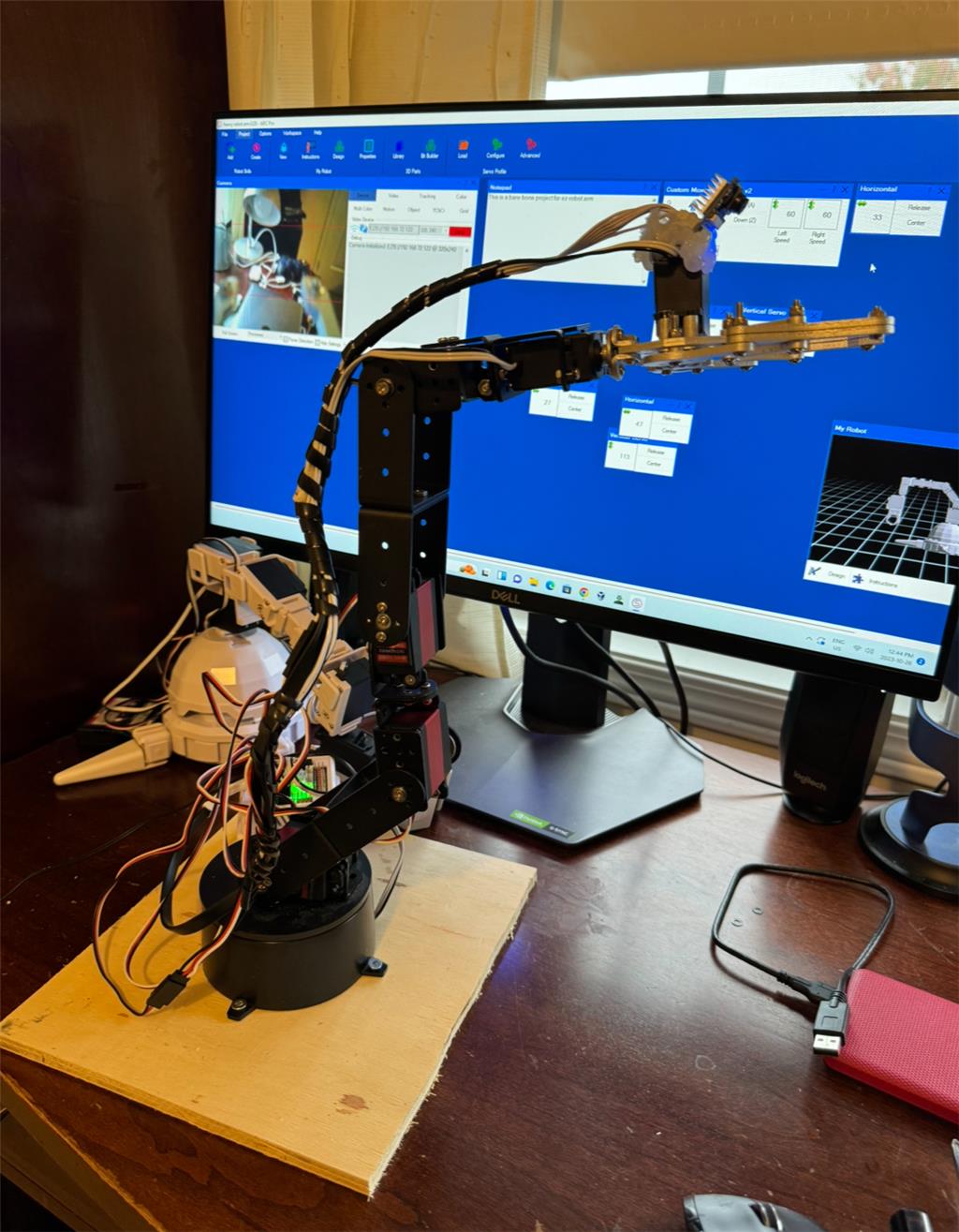
I made a quick arm that is a little more robust. I had to use a mix of 35kg servos and ez-robot servos as it has a lot of weight to it. It’s 7 DoF because I added one for the gripper and 2 in the Center but I can remove both of these if not supported. I put ez-robot servos near the end and on swivel and gripper and rotary base. I hot glued a camera on the gripper because umm why wouldn’t you!Okay nice! The second servo is redundant if you had another metal bracket to extend that arm to replace it.
A good test to see if you have more joints than needed (or not enough) is to grab the end effector and move it around the table to ensure it reaches the areas.
Oh, one more advice... the upper arm (closest to the rotation base) should be longer than the lower arm (closest to the gripper). You'll be able to reach inward toward the home (0, 0, 0) coordinate if the lower arm is a bit shorter than the upper arm. It'll also help your gripper hold more weight by having less mass on the lower joint.
I have a stack of brackets I purchased from China a few years ago so I will have a play with some different configurations. I really hate this gripper, why is this garbage claw so popular on robot arms? I will spend some time on thingverse and see if there is something a little more suitable.
Okay i have a GUI for designing the joint definitions. Here's a screenshot of how it'll work...
From the image it looks like 3DoF will be supported in calculation or is it 4DoF including the rotary server at the base (not shown in GUI). For the last servo that connects to the gripper will we measure to the end of the gripper? Should the servo range degrees include max and min or is this just set up when you configure the servo and you put what the delta is between max and min? What position will every servo need to be when we set this up or is this the offset degrees. Would it make sense to set a starting position for each servo during calibration (ie 0 or 180) ? Depending on the way the servo is mounted do we need to be able to specify if 0 degrees is forward or if 0 degrees is backwards?
Eak, lots of question before the chicken laid the egg
You can add as many joints to customize your robot arm. Press the ADD JOINT button to add. Or press DELETE to delete the joint. Yes. Each joint/bone has a length. No. The center of the servo range is used so you have a full range that starts from the center. You calibrate your servo attachments. Yeah i should probably add an inverse button there so the direction of the servo. It's also missing the actual servo port too. But that's because it's not done - it's a UI that i'm using to test the whole system with simulation before adding the final piece. I'm doing this robot skill on my own so it's a part-time gig