
Describe Your Robot Arm For Kinematic Robot Skill
We are in the process of developing a dynamic configuration system for robot arms, which will be compatible with a variety of robot arms and joint numbers. We kindly request your valuable input regarding your robot arm configurations to make this system as versatile and effective as possible.
One of the critical aspects of this project is understanding the layout and specifications of various robot arms. Your insights and contributions will significantly aid in developing this dynamic configuration system. Here's what we're interested in:
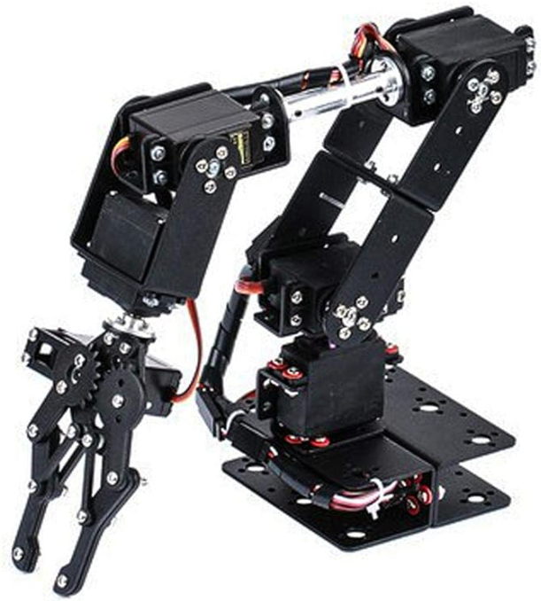
1. Configuration Description: Please describe or provide a picture of your robot arm's layout. Share details such as the number of joints and a brief overview of each joint's axis of motion. For example, does the base servo rotate the arms UP/DOWN, LEFT/RIGHT, or have any other specific functionalities?
2. Joint Axis Information: Provide specific details about each joint, including its range of motion, degrees of freedom, and any unique features or constraints.
By sharing these pictures or details about your robot arm (or plans), you can help us build a more inclusive and adaptable system, accommodating a wide range of robotic arms with different configurations. This system will open doors to numerous applications, including object manipulation through camera detection, remote control via hand tracking in VR, and many more.
Feel free to reply to this message with your robot arm details. Thank you for your time and expertise!

Be nice if it worked with a standard open source 3D printed arm with cheap PWM servos so we can all build them. Maybe something like the eezbotarm https://www.thingiverse.com/thing:1454048
I would advise against that robot arm because the second joint is lever-driven so the kinematic calculations won't be accurate. Can you post a different robot arm that uses a traditional and less complex assembly that you would like to build?
Reviewing that 3d model, i wonder if the lever is equal on both sides so it would be equal degrees. The challenge i'd be wondering is if the servo moves 10 degrees, does that result in the joint moving 10 degrees? The servo's rotation is critical for kinematic calculations.
This one would be extra easy to configure: https://www.amazon.ca/Mechanical-Analog-Steering-Manipulator-Industrial/dp/B081FC4Q52/ref=sr_1_12
I have all the pieces in my busy box to build that robot arm. The challenge with the cheap 996 servo's is that as soon as you have 6 DOF they don't have enough torque to barely lift themselves let alone hold an object heavier than a feather. I typically upgrade it with some 25Kg servos for the load bearing servos and they work reasonable well. You can see one on my roomba.
https://www.youtube.com/shorts/5ua8yFFzz28
edit I wonder if @Jeremie could come up with a quick design using EZ-Robot parts as most of us have these laying around. The dome from Six or Adventure bot with pegs around it may make a good base and the Claw from JD or Roli. Its opensource so we can all print the components. Just not sure if Servo's would hold up at 6 DOF either.
lol I wouldn’t be caught dead using the 996 servos hehe. Id swap them with ezrobot hdd in a heartbeat.
and yes the hdd servos will hold more than 6 dof. We’ve done some funny stuff with them plus they have stall protection
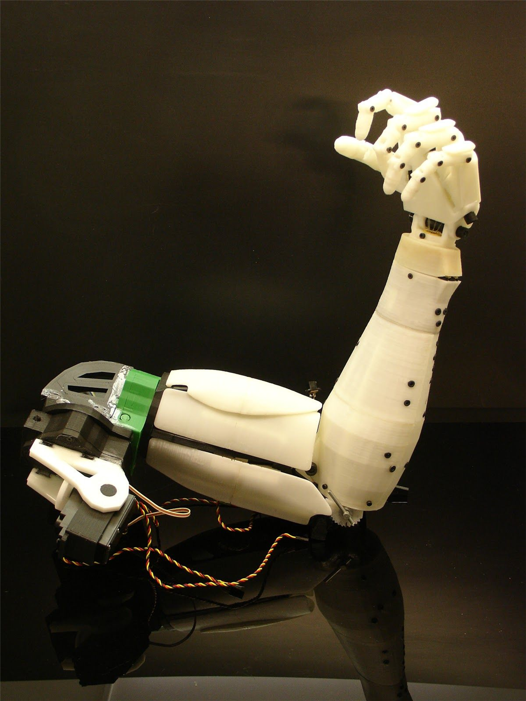
Maybe something like this.
Thank you, @nink, for confirming that this is a feasible configuration for the dynamic system. My reason for asking was to better understand the diverse configurations involved in constructing the 'kinematic builder' or 'joint builder.' I'm interested in exploring the various setups that can provide insight into which values and settings should be made available to the user. Striking the right balance is essential; too many settings can make the interface overly complex, while limiting them to popular use cases can simplify it.