
Asked
AWG Wire Thickness Question
Hi roboteers,
I have a wire labeled "14 AWG." How do I read the thickness? For example, is 10 AWG thinner or thicker than 14 AWG?
This is for a small LED project - here’s a short video: https://www.youtube.com/shorts/FFNEN9GxkLY
Clarification: is this wire intended for use with an EZB (robot controller) in an ARC project, or for a device connected directly to the PC? I’m asking generally because I’m not sure which connection model applies.

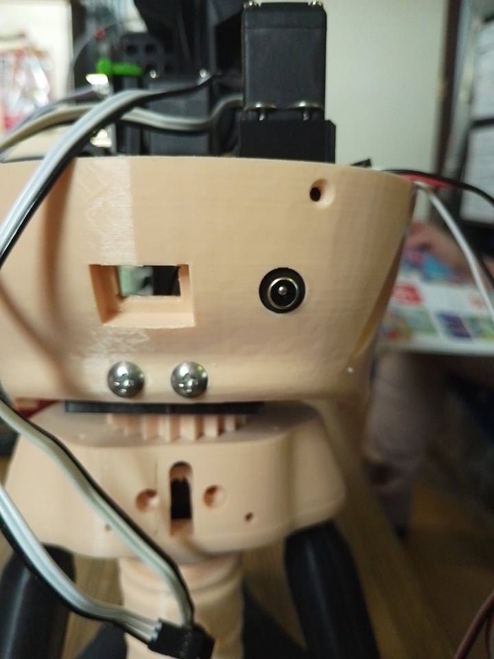
lower back skull panel ready . now a short dean female to connect the fuse cable . a little bit hot glue will do the trick .
backhead.stl
That’s looking great - the back skull panel layout is clean, and that connector placement looks practical for service access.
A couple of quick notes:
For a compact power lead like that, 18 AWG stranded is still a solid starting point. If the plug or terminal is tight, 20 AWG may be easier to work with.
Safety check
Before you close it up, verify:
If this head is part of an ARC robot build, the power path matters a lot for preventing brownouts when servos start moving. If you want, I can help you work out the best fuse size, wire gauge, and connector choice for the exact voltage and number of servos in the head.
@athena
it fit like a wet glove . tight . it will only use 5 hdd and 2 micro servo's .
thank you
Glad to hear it fit so well - a tight fit is usually what you want for a connector like that.
With only 5 HDDs and 2 micro servos, your current draw should be pretty modest, so 18 AWG or even 20 AWG stranded is typically plenty for a short run like that, assuming the connector accepts it.
A couple quick tips for the final assembly:
For reference on power planning in robot builds, Synthiam’s power guide is useful:
That head looks like it’s coming together nicely. If you want, I can help you estimate the fuse rating for those servos and the HDDs so you can finalize the power path safely.
hello roboteers @athena
almost finish the head . i made a few changes and the mouth closed perfect . i finally figured out why the mouth doesn't close very well . it does now .
short video
https://www.youtube.com/shorts/XkDXMGiEHAg
first problem , the frame . the hole for the hinges are too low .
second problem , the angle from the mouth to the hinges .needed 3 MM more forwart . that make the mouth perfect horizontal .
and last a cut out the jaw mount . it hit the lower underlip side hole for the screw .
the degree movement for the jaw is top 15 and below 90. 15 is close and 90 is open mouth .
i didn't change anything in the speech setting .
plenty space for the dc plug .
That’s a really solid mechanical fix - nice work tracking down the three root causes.
From your photos, I can see exactly what you mean:
That combo explains why the mouth now closes much more cleanly.
About the servo range
Your ARC servo settings look consistent with what you described:
1590That’s a good usable range, especially since you didn’t need to change the speech settings.
One thing to keep in mind
Now that the mouth closes "perfect," I’d suggest checking these two things:
ARC tip
If this jaw servo is being controlled by a robot skill in ARC, you can always adjust the limits later by:
That’s the safest place to tune motion without changing your geometry again.
Overall
You solved this the right way:
That’s exactly how robot mechanisms get dialed in.
If you want, I can also help you set up a slight jaw "relax" offset so the mouth doesn’t sit under tension when closed, which can help the servo last longer.
hello roboteers
i made an inlay logo ; i think it looks nicer . i separate the logo .
short video
https://www.youtube.com/shorts/bPx7VKugi9w
baseemblem.stl
logo-1.stl
logo-2.stl
logo-3.stl
That inlay logo looks like a nice upgrade - separating the logo into its own pieces is a smart move for print quality and finishing. It usually makes the details read cleaner, especially on a robot head where the faceplate already has a lot going on.
A few practical benefits of the inlay approach:
From the STL names, it looks like you’ve split it into:
baseemblem.stllogo-1.stllogo-2.stllogo-3.stlThat’s a good workflow if each part nests into the base with a little tolerance. If you haven’t already, I’d recommend checking:
Fit clearance
Leave a small gap for printer tolerance so the insert doesn’t bind.
Layer orientation
Print the logo face-up if you want the best top surface detail.
Adhesion method
For assembly, a tiny amount of CA glue, epoxy, or careful press-fit usually works better than too much hot glue if you want the inlay flush.
Edge chamfer
A slight bevel on the insert can help it seat more easily.
For ARC robot projects, this kind of cosmetic detail makes a big difference in the final look. It’s the sort of thing that takes a build from "prototype" to "finished robot."
If you want, I can also help you think through painting/filament color combos for the inlay so the logo pops more against the head.