Pulse Flash LED with PWM
Description
Pulse Width Modulation is the method of having a digital port, which is only On or Off to have a varying output voltage. Use this approach to flash and LED with a pulsing effect.
Step 1
DC electricity works by having Positive and Negative. An LED is short for a Light Emitting Diode. A diode prevents current from flowing both directions. Diodes only allow current to flow in one direction, and they’re always polarized. A diode has two terminals. The positive side is called the anode, and the negative one is called the cathode.
Current through a diode can only flow from the anode to the cathode, which would explain why it’s important for a diode to be connected in the correct direction.
Did You Know: Physically, every diode has some sort of indication for either the anode or cathode pin. Usually the diode will have a line near the cathode pin, which matches the vertical line in the diode circuit symbol.
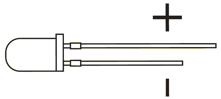
An LED has a physical indication of Anode and Cathode pins as well. LED stands for light-emitting diode, which means that much like diodes, they’re polarized. Find the longer leg, which indicates the positive, anode pin.
Connect an LED to port D0 of the EZ-B. In this example, we will provide power (+) to the LED from a signal pin of the EZ-B. The EZ-B will output +3.3 volts on the signal pin when it is in the ON state. The signal pin will respectively output GND when it is in the OFF state.
1) Connect the LED's Anode (+) wire to the signal (white) pin D0 of the EZ-B.
2) Connect the LED's Cathode (-) wire to the ground (black) pin D0 of the EZ-B.
The Code
Use the ServoSpeed() command to apply a ramping speed to the PWM. The PWM command to set the brightness. The PWM essentially turns the state of the digital pin ON and OFF hundreds/thousands of times per second to produce the result of a "varying" voltage. The PWM range is between 0% and 100%, called the Duty Cycle.
The ServoSpeed() command will configure Ramping between two PWM duty cycles.
Add an EZ-Script control to your project, edit and paste this code...Code:
# set the servo speed to 2
ServoSpeed(d0, 2)
:loop
# Set LED On
pwm(d0, 100)
# wait some time for the pwm to do its ramping thing
sleep(3000)
#set LED Off
pwm(d0, 0)
# wait some time for the pwm to do its ramping thing
sleep(3000)
goto(loop)
Tweak the Sleep() command time and the ServoSpeed() command time to see the different pulsing effects.
On the plus side, I guess I can count my blessings that trying this didn't make my EZ-B explode...
did you use a black/white wire to connect it on ezbv4 black and white ports?
Make sure you are connected to the EZ-B when you use the PWM skill. You don't even need a series resistor in line with the LED because the EZ-Bv4 and IoTiny have them on board.
Here's a quick video I made for you to show it working.
Video.zip
can you try pwm(d12,0) first line
and second pwm(d12,100)
can you give the part number used and the url/web site were you bought the LED?
...Edited...
Also have you tried a different LED?
Cheers
Making those modifications to the script didn't work.
@merne
I bought two 2760143 LEDs from the local Hobby Town, and neither is working.
I found the issue.
I code and I do code debugging a lot, and sometimes you need to debug other's people code,one of the most common mistakes is to assume specific conditions or listen to other people (developers) when you are debugging their code and ignoring the details because you trust their assumptions.
The most important thing details.... what kind of led you have ? if you don't know please post the part.
Everyone here assumed you picked the correct led, and you know how a led works.
Merne:
This is the 1M question
Bobsheaux:
Your led is a special led: INFRARED
https://en.wikipedia.org/wiki/Infrared
Science textbooks say we can't see infrared light. ... Like X-rays and radio waves, infrared light waves are outside the visual spectrum.
you are barking up the wrong tree,
LEDs don't work like ordinary lights:
They have a polarity, hence they must be powered using DC respecting that polarity. Reverse the polarity and they won't work. You may also damage them if you apply more than ~4V-5V in the reverse direction (these are safe values; the exact maximum tolerable value depends on the specific device).
Light emission begins only if a certain voltage is reached (Forward voltage), under that voltage the emission is negligible
After the Forward voltage is reached, any very slight increase in voltage makes the LED conduct heavily, i.e. absorb a huge current. Hence you need a resistor in series to limit that current to a safe limit.
Once conducting, the light intensity emitted is roughly proportional to the current (not voltage) that flows in the diode (so you get a brighter LED if you decrease the value of the limiting resistor). This up to the maximum current limit of the LED. After that limit has been reached, the led goes POOF!
Jeremie:
You can connect a led directly to EZB/Iotiny DIGITAL PORT because there's a resistor (inline) inside.
Bobsheaux:
@Bobsheaux: You shouldn't, you will damage.
Nomad:
@Nomad: Bad advise, please read about leds!
Nomad:
No, Jeremie already explained, @Nomad please read the posts!
Nomad:
@Nomad: voltage is not important, if you add a resistor with a correct value, you can connect a led to a 9v battery, Please READ ABOUT LEDS!
https://ohmslawcalculator.com/led-resistor-calculator
@Bobsheaux:
I'm assuming you have this led:
https://www.hobbytown.com/radioshack-highoutput-infrared-led-rsh2760143/p787932
And looking to your video it looks like the picture.
If not please post the correct part / link.
Regular leds:
https://www.hobbytown.com/miniatronics-5mm-dia.-blinker-flasher-led-1ea-red-green-yel-mnt1215003/p285117
so the only problem is a wrong led . if voltage is not a problem when using the ezbv4.
Regarding the Led current versus voltage, my answer is in context of the above scenario: EZ-Robot controller and generic leds.
bear in mind, not all leds are equal. Some leds have different forward voltages and/or max current values to operate. (high current = brighter)
https://www.hobbytown.com/radioshack-highoutput-infrared-led-rsh2760143/p787932
EZ-Robot controller values:
PIN Logic voltage: 3.3v
PCB Resistor : 330 ohms
Ohms law: Current = Voltage / Resistor
If your led has (typical) 1.2 forward voltage :
Current = (3.3 - 1.2) / 330 = 0.006 A => 6 milliamperes
If you could change the voltage to 5V and keeping the same resistor:
Current = (5 - 1.2) / 330 = 0.011A => 11 milliamperes
So increasing the voltage increases the current and the led will be more bright, but each led has specific limits if you cross the limit you will burn the led.
http://lednique.com/electrical-theory-basics/ohms-law-and-resistor-calculation/
once again I'm discussing the relevant information, leds are diodes and there are other i.e. bored details like saturation current, but let's keep it simple
I had only two classes of electronics, and it was long time ago... so i hope I'm not inducing more confusion
Jeremie is the expert... Jeremie are you there ?
just like if you test the led from a tv remote.
Infrared LED ON :
Infrared Led OFF:
Quote:
I bought two 2760143 LEDs from the local Hobby Town, and neither is working.
PTP Beat me to it me to the answer, Is an Infrared LED. PTP is a great and has helped me many many times PTP know his stuff.
@Bobsheau
You night have burn out your leds, I would try using you phone camera to see if it still working.
Then get the correct LED as ptp has given you a link...
Regular leds:
https://www.hobbytown.com/miniatronics-5mm-dia.-blinker-flasher-led-1ea-red-green-yel-mnt1215003/p285117
Don’t give up and keep learning. Ps, in my humble opinion, I would suggest in future questions when someone asks a question please give a direct answer this will help your frustration as people try to help you.
cheers
Great job PTP!
Thank you @PTP, I would have never thought that it was an IR LED! Good call looking into the part number.
@PTP is indeed correct. The voltage rating of an LED is usually referring to the diodes minimum forward voltage to overcome the voltage drop of the diode itself (normally forward voltage values are in the 1.2V to 3V range). Voltage is usually not a worry with LEDs as they can handle up to 20-30V (check the datasheet maximum voltage rating). LEDs are damaged by over current in most cases so you would have to increase the resistance as the voltage goes up in order to keep from over-currenting the LED.
In this case 3.3V from the signal pin (plus the inline 330ohm current limiting resistor) is always going to safely light up the LED, but if the light is invisible (like Infrared light) then you would have to use a digital camera to see the light. Please note that most phones and digital cameras now have Infrared light filters built-in these days so you'll need to use the lower quality front facing camera on your phone or an old digital camera.
@Bob if you want some visible colored light to come out of the LED you're going to need some new LEDs.
"I would suggest in future questions when someone asks a question please give a direct answer this will help your frustration as people try to help you."
I'd be less frustrated if this platform's suggestion of "ez" wasn't so misleading. Look at how deep we had to dig before we came upon the revelation that I bought the WRONG kind of LED for this project. Until individual LEDs are available for purchase in EZ-Robot's store, this tutorial needs to mention how if you're trying to get any kind of visible blinking action, you don't want to buy infrared LEDs.
And I'm not being indirect in my answering questions. Someone asks me a question, I tell them the information I THINK they're asking for.
[Quote
I'd be less frustrated if this platform's suggestion of "ez" wasn't so misleading. Look at how deep we had to dig before we came upon the revelation that I bought the WRONG kind of LED for this project. Until I'd be less frustrated if this platform's suggestion of "ez" wasn't so misleading. Look at how deep we had to dig before we came upon the revelation that I bought the WRONG kind of LED for this project. Until individual LEDs are available for purchase in EZ-Robot's store, this tutorial needs to mention how if you're trying to get any kind of visible blinking action, you don't want to buy infrared LEDs.EZ-Robot's store, this tutorial needs to mention how if you're trying to get any kind of visible blinking action, you don't want to buy infrared LEDs.
Of course I get the LEDs that don't give off any light... ]
-
IMHO, The document DJ wrote is not miss-leading, You also can buy a lot of other things that are on ez-robots store but remember ez-rotor is not owned by Synthiam so DJ does not have any control what EZ-Robot’s store sells.
As the old saying goes, if you don’t learn something every day you’re missing out or something like that. ;-)
Now you know the difference between infrared and visible light admitting diode’s. AFAIK I thought everyone knew the difference.
keep on building keep on trucking.
Be well, cheers
Sorry you had to get the long version of LEDs, great info, maybe a little over kill from DJ's original post... :-)
Here is the simple version:
here is the LEDs I used - $8.98 for many types
https://www.amazon.com/Haitronic-assorted-Prototyping-breadboard-circuitry/dp/B01MYWS9IW/ref=sr_1_2?dchild=1&keywords=led+hobby&qid=1598022758&sr=8-2
You do need some hobby Male to Male Lead Plug Extension Wires - cheap on Amazon
I simply plug is a few light-emitting diode - LEDs per DJ’s instructions:
DJ - quote:
Did You Know: Physically, every diode has some sort of indication for either the anode or cathode pin. Usually the diode will have a line near the cathode pin, which matches the vertical line in the diode circuit symbol.
An LED has a physical indication of Anode and Cathode pins as well. LED stands for light-emitting diode, which means that much like diodes, they’re polarized. Find the longer leg, which indicates the positive, anode pin.
Connect an LED to port D0 of the EZ-B. In this example, we will provide power (+) to the LED from a signal pin of the EZ-B. The EZ-B will output +3.3 volts on the signal pin when it is in the ON state. The signal pin will respectively output GND when it is in the OFF state.
1) Connect the LED's Anode (+) (long side) wire to the signal (white) pin D0 of the EZ-B.
2) Connect the LED's Cathode (-) (short side) wire to the ground (black) pin D0 of the EZ-B.
The Code
Use the ServoSpeed() command to apply a ramping speed to the PWM. The PWM command to set the brightness. The PWM essentially turns the state of the digital pin ON and OFF hundreds/thousands of times per second to produce the result of a "varying" voltage. The PWM range is between 0% and 100%, called the Duty Cycle.
The ServoSpeed() command will configure Ramping between two PWM duty cycles.
Add an EZ-Script control to your project, edit and paste this code...
Code:
In ARC open a script and put:
# set the servo speed to 2
ServoSpeed(d0, 2)
:loop
# Set LED On
pwm(d0, 100)
# wait some time for the pwm to do its ramping thing
sleep(3000)
#set LED Off
pwm(d0, 0)
# wait some time for the pwm to do its ramping thing
sleep(3000)
goto(loop)
Tweak the Sleep() command time and the ServoSpeed() command time to see the different pulsing effects.
In ARC I opened the PWM control and used the "PWM Slider" to turn the LED on / off
I did it and it worked perfectly
If you need a video, I can make one for you.
EzAng
I always finish and understand a project before I go on to something else.
EzAng
https://youtu.be/d6RR5tw8jx0?t=51